manuals.online logo
Brands
  1. Home
  2. •
  3. Brands
  4. •
  5. Sonance
  6. •
  7. Speakers
  8. •
  9. Sonance DR Series User manual

Sonance DR Series User manual

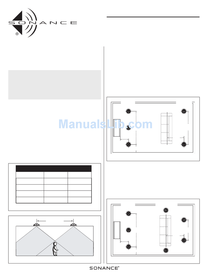
INSTALLATION INSTRUCTIONS
DR7001/DR5501/DRS001
CEILING PLACEMENT SPEAKERS
c
PN.33-1067 2.00
INTRODUaiON INSTALLATION
Thank you for purchasing apair of DR-Series speakers from
Sonance. When properly installed, this product will provide you
with years of entertainment pleasure. To obtain the full poten¬
tial of your new speakers, please read all instructions before
starting the installation. If you do not have the necessary skills
to install the speakers yourself, contact your authorized
Sonance dealer for installation options.
ExistingConstruction
1. Survey proposed sites and look for installation obstacles
(e,g., plumbing, wiring, and other fixtures). Access the attic
or crawl space to check routing of air ducts and available
mounting depth (see Specifications on back) for your specif¬
ic model.
2. At each selected site, use astud locator to identify an open
space between studs.
3. At each site, use the enclosed mounting template to cut a
holeata45-degreeangle,asshowninFigure1.Thistech¬
niquewill allowyoutoeasilyrepair thedrywall if youmake
amistake.
PARTSLIST
Each DR-Series package includes the following items:
●(2) DR7001 (or DR5501 or DR 5001) speakers with integral
FlexBar™ mounting systems
●(2) Paintable grilles
●(2) Paint plugs (protects speakers during painting)
●(1) Mounting template (in packaging)
InsideCeiling
Remove Drywoll CeilingDrywall(sideview)
f45° cut
PUCEMENT/APPLICATION
Unlikeconventionalspeakers,SonanceDR-Seriesspeakersdonot
require aspecific orientation to sound good. They are ideal for use
in ceilings in hallways or living rooms.And since they are built
with weather-resistant components, you can even mount them in
outside protected areas, such as aporch or gazebo ceiling.
NOTE:DonotmountanyDR-Seriesspeakerinalocationthatisexposed
directlytoweatherelements.
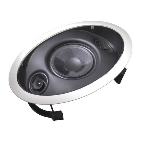
EachDR-Seriesspeakerisa3-wayspeakersystemthatfeatures
extended bandwidth, high-power handling, and aunique pivot¬
ing tweeter that can be aimed to fire directly at the listening area.
Moreover, the DR7001 and DR5501 models include room equal¬
ization switches, so you can exactly tailor the frequency response
to compensate for existing room acoustics (see SonicAdjustments
on page 3).
With these features, you’ll find that DR-Series speakers are also a
perfect choice to reproduce stereo surround sound in next-gen¬
erationDolbyAC-3™andDTS™hometheatersystems.Andthey
are designed to work with our D-Series in-wall speakers which
would serve as main speakers for front-channel reproduction.
Contact your authorized Sonance dealer for recommendations.
CutOut
Figure I-Cutting ceiling drywall at a45° angle.
4.Usethefollowingcharttodeterminethespeakerwiregauge
for the length required for your application:
18 gauge =50 feet or less 14gauge=150feetorless
16 gauge =100 feet or less 12 gauge =200 feet or less
5. With all audio system power off, connect and run speaker
wire from the amplifier or receiver through the wall or ceil¬
ing, leaving afew feet exposed at each site opening.
6. Strip Va" off the wire ends and connect them to terminals on
the back of each DR-Series speaker, as shown in Figure 2. Be
sure to observe correct polarity color-codes (i.e., red is -I- and
black is -).
DR-SeriesSpeaker
(rear view)
Figure 2-DR-Series connections.
...continued on next page
1
New Construction
ThismethodrequiresusinganoptionalFlexBracket™(90-1358)
foreachspeaker.AvailablefromSonancedealers,thisaccessory
servesasareminderandguideforthedrywallinstaller.
1. At each site, check the available mounting depth (see
Specifications)andfastenaFlexBrackettostuds,asshown
in Figure 4.
2.Usethefollowingcharttodeterminethespeakerwiregauge
for the length required for your application:
18 gauge =50 feet or less 14 gauge =150 feet or less
16gauge =100feet orless12gauge=200 feetor less
3.Connectandrunspeakerwirefromtheamplifierorreceiv¬
ertoeachFlexBracketopening,leavingafewfeetexposed
and taped to each site opening.
4.After the drywall is installed, perform steps 6through 10, as
listed previously in Existing Construction.
INSTALLATION
ExistingConstruction(continued)
7. (Optional) If desired, you can insulate the cavity behind
eachspeakeropeningtoreducesoundfromtravelingand
vibrating at other locations. Loosely fill the cavity with sev¬
eral square feet of fiberglass (with faced side away from
speaker, if applicable).
8. Install aspeaker into each opening so that the longer ends
oftheFlexBarsgoinfirst,asshowninFigure3(onpage2).
ThenpositioneachspeakersobothFlexBarendsarebehind
the drywall.
9. On the front of each speaker, tighten all screws evenly until
the FlexBars firmly grip the back side of the drywall (see
Figure 3). The speaker baffle should be flush with the wall
and not bowed. If needed, untighten each screw alittle to
easeanytension.
DR-$eriesSpeakerInCeiling
PAINTINGYOURSPEAKERS
FlexBarOnDrywall
PaintingABaffle
1.Removethecircularpaintplugsenclosedwiththepackage.
2. Carefully place aplug onto each installed speaker without
grille; bend the four tabs over and insert them into the
grille channel.
3.After the paint is dry, remove each plug by using the center
finger hole.
PaintingAGrille
1. Place each grille onto aclean surface and lightly spray the
front with thin paint (i.e., l-to-5, paint-to-agent). Do not
plug holes.
2. If desired, paint each grille’s underside after the front is dry.
3. After the grilles have dried, carefully insert them into the
installed speakers.
TightenScrews
Figure3-InstallingtheDR-Seriesspeaker.
10. If painting is not required, carefully insert agrille into each
speakerbaffle.Otherwise,seePaintingYourSpeakers.
Stud StudBrace
I1.5"minimum
●●.
Fasteners
FlexBracket
(90-1358forDR-series)
i.5" minimum
Figure 4-Fastening aFlexBracket.
2
SONICADJUSTMENTS DR7001Speaker
(frontview)
Each DR-Series speaker features apivoting tweeter and two
models, the DR7001 and DR5501, also include room equaliza¬
tion switches for custom tailoring of the frequency response.
AdjustingThePivotingTweeter
Adjusting the pivoting tweeter is easy -simply press on the
outside plate to aim the tweeter so it firesat adesiredlistening
area, as shown in Figure 5.
IMPORTANT: Do not press the tweeter itself. Doing so, may damage
the component and cause distortion or poor performance.Also, on
the DR7001, do not press or remove the tweeter’s protective mesh.
DR-SeriesSpeaker
(frontview)
SettingADIPSwitch
'///:
*,SpeakerEQSettings
FLAT
●O 9 0 O●
_«0 *0 o^
oo● ●o
WS5 0●o o●mo
riKBii
Xi "f Do
Oo
□n700i
Tweeter
Figure 6-DR7001 room equalization settings.
DR5501Speaker
(front view)
PressRingAtAnyPoint
To M o v e Tw e e te r
SettingADIPSwitch
Figure5-AdjustingtheDR-Seriespivotingtweeter.
Herearesomesuggestionsforaimingatweetertoobtainopti¬
mumperformance.Foradditionalhelp,contactanauthorized
Sonance dealer:
●If apair of speakers is widely separated and the stereo
imageisnotfocused,aimthetweeterstowardseachother.
●Conversely, if apair of speakers are closely spaced or the
music seems to build up in one area, aim the tweeters out¬
ward to provide more spaciousness.
●At the listening area, if the music seems too bright, try aiming
the tweeters away from listeners (also see Adjusting Room
Equalization Switches).
●If room acoustics seem dull (e.g., heavy carpeting, drapes,
etc.), aim the tweeters at the listening area to compensate
for the inherent high-frequency rolloff (also see Adjusting
Room Equalization Switches).
AdjustingRoomEqualizationSwitches(forDR7001/DR5501Only)
The DR7001 and DR5501 include room equalization switches
so you can custom tailor the speaker system response to better
match the room’s acoustics.
The DR7001 features four DIP switch settings, while the
DR5501 has three. Figures 6and 7show the locations and how
to set the switches for some common applications. If you need
further help, contact an authorized Sonance dealer or our
Tech nic a l Ass ist a nce D epar tmen t (se e n ext p age) .
IMPORTANT: Turn ojf all audio power before changing any room
equalization switches.
*,SpeakerEQSettings
FLAT
,●0 *0 o«
^●O 90 09
●OO●*0
miMP UVt DEID
IRIBll
□o|nyr?i| ●
□R5S01
Figure 7-DR5501 room equalization settings.
Below are some additional notes for setting the room equaliza¬
tion switches:
●FLAT is the default factory setting. Initially, try this setting
as you listen to avariety of music. In most cases, this setting
will suffice.
●If the room is “live” (e.g., wood or tile floors, modern furni¬
ture, lots of glass windows or doors, etc.), try attenuating
the high frequencies with the example “live” setting in
Figures 6or 7.
●If the room is “dead” (e.g., heavy carpeting, plush furniture,
expansive drapes, etc.), try boosting the high frequencies
with the example “dead” setting in Figures 6or 7.
3
5. Write the Return Authorization Number on the outside of
the shipping carton. For warranty work, please include a
copy of the original bill of sale inside the package.
6. Ship the packaged unit to:
Tech nic a l Ass ista nce Depa rtme nt
Sonance
961 Calle Negocio
San Clemente, CA 92673-6202
SPECIFICATIONS
DR500I
Si’TAKER Model: DR7001 DR5501
Infinite baffle
3/4" (19 mm) pivoting
aluminum-dome with polycarbonate-dome
neodymium magnet
and l'crrofluid™-cooled
voice coil
2-1/2" (63.5 mm)
polypropylene cone
with Ferrofluid""-cooled
voice coil
8" (203 mm) dual
voice-coil, reinforced
glass composite cone
with reverse-rubber
surround
Infinite baffle Infinite baffle
5/8" (16 mm) pivoting 5/8" (16 mm) pivoting
polycarbonate-dome
Speaker Design:
T w e e t e r Ty p e :
Midrange Type: 2-1/2" (63.5 mm)
polypropylene cone
2-1/2" (63.5 mm)
polypropylene cone
WARRANTYCOVERAGE(USAONLY)
Woofer Type: 8" (203 mm)
polypropylene cone
with reverse-rubber
surround
8" (203 mm)
polypropylene cone
with reverse-rubber
surround If, within five (5) years from the date shown on the bill of sale, the
unit fails, due to adefect in workmanship or material, Sonance will,
at its option and at no charge, repair or replace the components of
such unit which prove to be defective.
For this warranty to be effective, the bill of sale must show that the
unit was purchased from an “Authorized Sonance Dealer” and must
list the price paid. This warranty shall apply exclusively to the origi¬
nal purchaser and shall not apply to units purchased for industrial
or co m me r c ia l u s e.
Furthermore, this warranty shall not apply if:
1. Damage to the unit was caused by accident, abuse, or misuse;
2. The unit was opened, modified, or repaired by unauthorized
personnel; or
3. The unit was not used as outlined in the operating instructions.
ExclusionsandLimitations
The warranty set forth above is in lieu of all other warranties,
express or implied, of merchantability, fitness for aparticular
purpose, or otherwise. The warranty is limited to Sonance
products registered herein and specifically excludes any dam¬
age to loudspeakers and other allied or associated equipment
which may result for any reason from use with this product.
Sonance shall, in no event, be liable for incidental or conse¬
quential damages arising from any breach of this warranty or
otherwise. This warranty gives you specific legal rights, and
you may have other rights which vary from state to state.
32 Hz-20 kHz,
±2dl!
iMFEDANCE (.MINIMUM): 6Q(4 H)
Power Handling:
Frequency Response: 35 Hz ~20 kHz,
±3dB
812(6 0)
39 Hz ~20 kHz,
±3dB
8a(6 O)
5-iOO watts5-125 watts 5 ~ 1 0 0 w a t t s
Efficiency: 91dB@lW/m 90 dB @1W/m 90 dB @1W/m
Grilles: While doth or metal White doth or metal White doth or metal
4DIP switches for
frequency tailoring
Dimensions, diameter: 12" (304 mm)
Dimensions, depth:
Grille, Diameter:
3DIP switches for
frequency tailoring
12" (304 mm)
4-l/2"(114mm)
9-19/32" (244 mm)
9-15/16" (252 mm)
Adiustments: N/A
12" (304 mm)
4-1/2" (114 mm)
9-19/32" (244 mm)
9-15/16" (252 mm)
Weather resistant
component and
hardware
1.25 ft-^
4-1/2" (114 mm)
9-19/32" (244 mm)
FlexBar Cltoutdiam.: 9-15/16" (252 mm)
Si’ECiAL Features: Weather resistant
components and
hardware
Weather resistant
components and
hardware
2.75 fl-^ 1.65 fPBa c k- B o. x Vo l u m e :
TECHNICALASSISTANCE
If you any have questions about the operation or installation of
your Sonance speakers, please call our Technical Assistance
Department on any business day at;
●(800) 582-0772 or (714) 492-7777; from 9a.m. to 5rm., PST.
OBTAININGSERVICE
If your product should need repair or service, contact your autho¬
rized Sonance dealer for help or use the following procedure:
1. Prior to calling, note the product’s model number, purchase
date, and original dealer’s name and address.
2. Contact our Technical Assistance Department at the above
number(s) and describe the problem the unit is experiencing.
If applicable, they will issue aReturn Authorization Number.
IMPORTANT: Do not return the unit to Sonance without first
obtaining aReturn Authorization Number.
3. If you’re directed to return the unit to Sonance for repair, pack
the unit in its original shipping carton. If needed, you can
obtain replacement packaging from us for asmall charge.
4. Contact United Parcel Service, Federal Express, or RPS to
arrange prepaid (not collect) shipping. Do not use the U.S.
Mail Service.
Declaration of Conformity
We, Sonance
212 Avenida Fabricante
San Clemente, CA 92672-7531
U.S.A.
declare in own responsibility, that the product described in this owner’s manual
is in compliance with technical standards;
EN 50082-1:1992
EN 55013:1993
EN 50020:1994
IMPORTANT; Freight collect shipments will be refused. Chip Brown
Sonance
San Clemente, CA U.S.A.
Sonance ■212 Avenidn Fabricante ●San Clemente, CA 92672-7531, USA ■(800)582-7777 or (949)492-7777 ●FAX: (949)361-5151 ■Technical Support: (800) 582-0772
This manual suits for next models

3

Other Sonance Speakers manuals

Sonance C201SQ User manual

Sonance

Sonance C201SQ User manual

Sonance INVISIBLE IS8T Series User manual

Sonance

Sonance INVISIBLE IS8T Series User manual

Sonance VPXT6R Instruction Manual

Sonance

Sonance VPXT6R Instruction Manual

Sonance Mariner 63 User manual

Sonance

Sonance Mariner 63 User manual

Sonance MAGO6V2 User manual

Sonance

Sonance MAGO6V2 User manual

Sonance IS4 C User manual

Sonance

Sonance IS4 C User manual

Sonance VISUAL PERFORMANCE VP10SUB NC Enclosure User manual

Sonance

Sonance VISUAL PERFORMANCE VP10SUB NC Enclosure User manual

Sonance Silhouette I Service manual

Sonance

Sonance Silhouette I Service manual

Sonance SONOS OUTDOOR Series User manual

Sonance

Sonance SONOS OUTDOOR Series User manual

Sonance Visual Performance VP85 User manual

Sonance

Sonance Visual Performance VP85 User manual

Sonance CRK10 User manual

Sonance

Sonance CRK10 User manual

Sonance Ellipse 2.0 LCR User manual

Sonance

Sonance Ellipse 2.0 LCR User manual

Sonance Visual Perfomance VP62LCR User manual

Sonance

Sonance Visual Perfomance VP62LCR User manual

Sonance PS-C43RT User manual

Sonance

Sonance PS-C43RT User manual

Sonance C101 Quick start guide

Sonance

Sonance C101 Quick start guide

Sonance SONOS User manual

Sonance

Sonance SONOS User manual

Sonance MODERNO M6R SST SINGLE-STEREO TECHNOLOGY User manual

Sonance

Sonance MODERNO M6R SST SINGLE-STEREO TECHNOLOGY User manual

Sonance Mariner 51 User manual

Sonance

Sonance Mariner 51 User manual

Sonance VIRTUOSO V831DR User manual

Sonance

Sonance VIRTUOSO V831DR User manual

Sonance CRK 20 User manual

Sonance

Sonance CRK 20 User manual

Sonance VP6R BPC User manual

Sonance

Sonance VP6R BPC User manual

Sonance PROFESSIONAL Series User manual

Sonance

Sonance PROFESSIONAL Series User manual

Sonance VISUAL PERFORMANCE VP82 Installation guide

Sonance

Sonance VISUAL PERFORMANCE VP82 Installation guide

Sonance PROFESSIONAL PS-C43RTLP User manual

Sonance

Sonance PROFESSIONAL PS-C43RTLP User manual

Popular Speakers manuals by other brands

YORKVILLE COLISEUM C170 brochure

YORKVILLE

YORKVILLE COLISEUM C170 brochure

Audio Pro Image Series Image 22 Specifications

Audio Pro

Audio Pro Image Series Image 22 Specifications

Kramer Galil 6-AWAll user manual

Kramer

Kramer Galil 6-AWAll user manual

Tannoy i12 user manual

Tannoy

Tannoy i12 user manual

Teufel L 430 FR Technical description and operating instructions

Teufel

Teufel L 430 FR Technical description and operating instructions

Insignia NS-3698 Setup guide

Insignia

Insignia NS-3698 Setup guide

Sonos ZONEPLAYER 100 Setup guide

Sonos

Sonos ZONEPLAYER 100 Setup guide

WhiteLabel BSK26 user guide

WhiteLabel

WhiteLabel BSK26 user guide

Sprout Immerse product manual

Sprout

Sprout Immerse product manual

Indiana Line NANO Series owner's manual

Indiana Line

Indiana Line NANO Series owner's manual

Behringer TRUTH B3030A Specification sheet

Behringer

Behringer TRUTH B3030A Specification sheet

LAMAX MusiCan1 user manual

LAMAX

LAMAX MusiCan1 user manual

Charge IT CH-4335 instruction manual

Charge IT

Charge IT CH-4335 instruction manual

Proficient Audio Systems F400slvr owner's manual

Proficient Audio Systems

Proficient Audio Systems F400slvr owner's manual

Audio Pro Bravo FX-04 user guide

Audio Pro

Audio Pro Bravo FX-04 user guide

Fender Passport PD-250 instruction manual

Fender

Fender Passport PD-250 instruction manual

Klein + Hummel O110 Installation and operation

Klein + Hummel

Klein + Hummel O110 Installation and operation

Acoustic Preference GRACIO 2.0 owner's manual

Acoustic Preference

Acoustic Preference GRACIO 2.0 owner's manual

manuals.online logo
manuals.online logoBrands
  • About & Mission
  • Contact us
  • Privacy Policy
  • Terms and Conditions

Copyright 2025 Manuals.Online. All Rights Reserved.