2
such as attics. Areas with exposed joists present a significant
danger of injury from falls or stepping on nonstructural sur-
faces.Before working in areas with exposed joists,always create
temporary walkways using plywood or dimensional lumber.
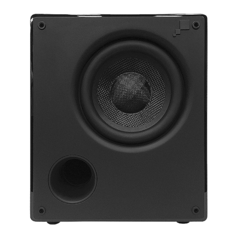
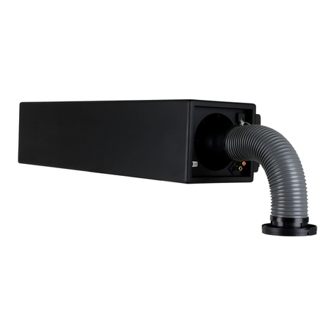
CINEMA SUB WITH BACK BOX, NEW CONSTRUCTION –
BACK BOX INSTALLATION
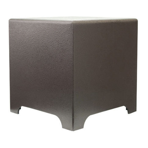
Insert the Cinema SUB back box between studs, moving the
studs if necessary to achieve proper fit. Attach the back box
with the L brackets provided, or if back box is installed against
the floor plate, use long 2-1/2" screws through the studs into
the sides of the back box every 6". For optimum performance,
mount back boxes as low and near to a corner as possible.
Drill a hole as small as possible in the rear or side panel of the
back box and pass the speaker wire through it. For ease of
speaker installation, Leave two feet of extra wire beyond the
actual speaker mounting location. Seal the hole with silicone
caulking compound.
CINEMA SUB ACOUSTIC ENCLOSURE INSTALLATION
Speaker Placement – Survey sites for installation obstacles
such as plumbing, wiring, and other fixtures.Access the attic or
crawl space to check routing of air ducts and available mount-
ing depth: Cinema Subs require 3-3/4" of wall depth and 2
cubic feet of volume.
At each selected site, use a stud locator to identify an open
space between studs. Drill a small hole in the center of the cho-
sen area and insert a bent coat hanger to confirm that the cav-
ity is clear.
Retrofit Hole – Using a level and draw a line around the card-
board cutout template to use as a pattern for cutting the hole.
Use a drywall saw to cut the hole,keeping the edges square and
paying particular attention to keeping the horizontal cuts level.
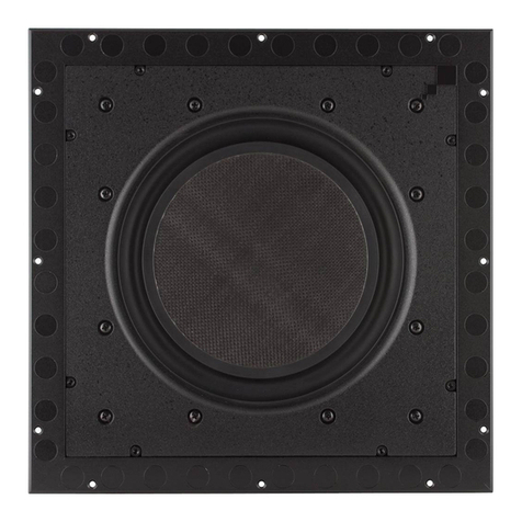
1. Remove Roto-Lock screws and toggle feet.
2. Remove six (6) Roto-Lock towers.
3. Using six (6) Roto-Lock screws, attach subwoofer to back box.
Insulation and Caulking – Silicone caulking compound should be
used to seal the junctions of fire stops, floor plate, and studs.The
stud bay should be as air tight as possible.Fill cavity with unfaced
fiberglass batting.
Secure drywall with screws every three to four inches in the
studs,fire stop(s) and floor plate that define the SUB enclosure.
Apply a bead of caulking compound to both the front and back of
studs around the perimeter of the enclosure. Reach through the
mounting ring to apply caulk.
Leave two feet of extra wire for ease of speaker installation.Attach
the wire to the bracket with a cable tie.
SPEAKER INSTALLATION
Wire Connections – Strip 1/2" of insulation from each speaker
wire.Attach the positive conductor to the red 5-way binding post
and the negative wire to the black post.To connect,loosen the nut
on the binding post until the hole in the post is visible.Insert the
stripped end of the wire through the hole, then snug the nut. Do
not over tighten.
Speaker Mounting –Screw each speaker assembly by inserting
the six screws provided through the baffle into the back box.
Replace the grilles.
CONNECTING THE CINEMA SUB AMPLIFIER
The Sonamp Cinema 260 specially is designed to drive subwoofers.
Connect the sub-woofer output interconnect to the left channel
input jack on the rear of the Cinema 260.If the source preamplifier
has no dedicated subwoofer output, use a pair of interconnect
cables from the preamp out to the left and right input jacks of the
Cinema 260.
If no line level output is available to drive the subwoofer, use a
Sonance OP-3 to convert high level speaker output to the
appropriate level for input to the Sonamp Cinema 260.Connect
subwoofer speaker wires to the right and left speaker terminals
on the back of the amplifier.
NOTES: Polarity of speaker wires is critical. All positive leads
(+) must be attached to red connectors throughout the system.
Since the Sonamp Cinema 260 subwoofer amplifier sends a
monaural signal to both speakers, either speaker (right or left)
may be driven by either amplifier channel.
The Sonamp Cinema 260 subwoofer amplifier is designed to
drive one speaker per pair of binding posts. Connecting addi-
tional speakers in parallel may cause damage to the speakers
and amplifier.
Do not tie amplifier output (+) terminals together and run a sin-
gle 2 conductor to the two subwoofers. Each amplifier channel
requires separate positive (+) and negative (-) conductors,4 total
for each amplifier and two subwoofer modules.(See diagram 4)
Plug the power cord into anAC outlet of the voltage indicated on the
amplifier.Do not use a switched outlet on another component.
Diagram 3
