Sonardyne Lodestar AHRS User manual

Lodestar AHRS
Operation Manual
Document Ref: UM-8084-107-A
6
Issue: A –
Rev 6
© Sona
rdyne International Limited 2013
1
UM-8084-107
Lodestar AHRS Operation
Manual
Head Office
Sonardyne International Limited
Blackbushe Business Park
Yateley, Hampshire
GU46 6GD United Kingdom
T. +44 (0) 1252 872288
F. +44 (0) 1252 876100
E. support@sonardyne.com
www.sonardyne.com

Lodestar AHRS
Operation Manual
Document Ref: UM-8084-107-A
6
Issue: A –
Rev 6
© Sona
rdyne International Limited 2013
2
Document History
Issue
Rev
Date
Comments
Section
Page
A
A
A
A
A
A
A
0
1
2
3
4
5
6
11-Jun-10
15-Nov-10
27-June-11
15-Sep-11
5-July-11
19-Nov-12
24-May-13
First issue
Minor changes to make terms consistent
Added DOC warning and E1 changes
Updates for V2.03 firmware release
Updates for PC Utility release
Formatting changes
ECN12243 New section – File Transfer and
updated Appendix A
All
5.5, 5.9
All
All
All
All
6.10 and
Appendix A
All
All
All
All
All
All
All
Copyright 2013 Sonardyne International Limited.
Blackbushe Business Park
Yateley, Hampshire GU46 6GD
United Kingdom
Tel: +44 (0)1252 872288
Fax: +44 (0)1252 876100
All rights reserved. No part of this document shall be reproduced, stored in a retrieval system or
transmitted by any means, electronic, mechanical, photocopying, recording, or otherwise, or translated
into any language without the written permission of Sonardyne International Limited.

Lodestar AHRS
Operation Manual
Document Ref: UM-8084-107-A
6
Issue: A –
Rev 6
© Sona
rdyne International Limited 2013
3
Contents
Document History.................................................................................................................................... 2
Contents .................................................................................................................................................. 3
Figures .................................................................................................................................................... 4
Tables...................................................................................................................................................... 5
1U.S. Department of Commerce License......................................................................................... 6
2Lodestar AHRS Operation Manual ................................................................................................. 6
2.1 Introduction................................................................................................................................. 6
2.2 What is the Lodestar AHRS? ..................................................................................................... 6
3Output and Alignment ..................................................................................................................... 7
3.1 Lodestar Output and Alignment ................................................................................................. 7
4Installation Preparation ................................................................................................................. 13
4.1 Installation Preparation............................................................................................................. 13
5Installation and Physical Configuration......................................................................................... 15
5.1 Typical Lodestar AHRS configuration ...................................................................................... 15
5.2 Installation ................................................................................................................................ 17
6Configuration using Lodestar PC Utility........................................................................................ 18
6.1 Installation and Connection ...................................................................................................... 18
6.2 System ..................................................................................................................................... 19
6.3 Gyro-Compass ......................................................................................................................... 22
6.4 Offsets...................................................................................................................................... 24
6.5 Console, C1, C2, E1, T1 and T2 Ports..................................................................................... 26
6.6 Ethernet and Ethernet (E1) Ports ............................................................................................. 28
6.7 Analogue Output Tab ............................................................................................................... 30
6.8 Time ......................................................................................................................................... 31
6.9 Output Check ........................................................................................................................... 33
6.10 File Transfer......................................................................................................................... 35
7Alarms .......................................................................................................................................... 39
7.1 Introduction............................................................................................................................... 39
Appendix A - Lodestar Angle Definitions............................................................................................... 40
Appendix B - Effect of Misalignment Errors .......................................................................................... 41
Appendix C - Fine Alignment Methods.................................................................................................. 42

Lodestar AHRS
Operation Manual
Document Ref: UM-8084-107-A
6
Issue: A –
Rev 6
© Sona
rdyne International Limited 2013
4
Figures
Figure 1 – Lodestar Reference Frame .................................................................................................... 7
Figure 2 – Lodestar Mounting Angle Gamma (Heading) Example ......................................................... 9
Figure 3 – Lodestar Mounting Angle Beta (Pitch) Example .................................................................... 9
Figure 4 – Lodestar Mounting Angle Alpha (Roll) Example .................................................................... 9
Figure 5 – Example ROV mounting of Subsea Lodestar ...................................................................... 10
Figure 6 – Lodestar Heave Definition.................................................................................................... 11
Figure 7 – Typical Installation of the surface Lodestar.......................................................................... 15
Figure 8 – Typical Installation of the subsea Lodestar .......................................................................... 16
Figure 9 – Configuration Software Main Window (not connected)........................................................ 19
Figure 10 – Lodestar Serial Connection Settings.................................................................................. 19
Figure 11 – Lodestar Ethernet Connection Settings ............................................................................. 20
Figure 12 – Configuration Software Main Window (connected)............................................................ 20
Figure 13 – Manual Latitude Setting Panel ........................................................................................... 22
Figure 14 – Automatic GPS Compensation Panel ................................................................................ 23
Figure 15 – Heave Filter Panel.............................................................................................................. 23
Figure 16 – Mounting Angles and Offsets Panel................................................................................... 24
Figure 17 – Remote Points List............................................................................................................. 24
Figure 18 – Port Settings Panel ............................................................................................................ 26
Figure 19 – Output Message Table....................................................................................................... 27
Figure 20 – IP Port Configuration Panel................................................................................................ 28
Figure 21 – Ethernet Output Message Table ........................................................................................ 29
Figure 22 – Analogue Port Tab ............................................................................................................. 30
Figure 23 – Clock Settings panel .......................................................................................................... 31
Figure 24 – ZDA Port Panel .................................................................................................................. 31
Figure 25 – PPS Port panel................................................................................................................... 32
Figure 26 – Dynamic Display................................................................................................................. 33
Figure 27 – Terminal check of GPS compensation .............................................................................. 34
Figure 28 – Example GPS output in HyperTerminal ............................................................................. 34
Figure 29 – Lodestar Ethernet Connection ........................................................................................... 35
Figure 30 – Lodestar Ethernet Port 4000 Configuration........................................................................ 36
Figure 31 – Lodestar Ethernet Port 4001 Configuration........................................................................ 36
Figure 32 – Lodestar C1 Port Connection............................................................................................. 36
Figure 33 – Lodestar C1 Port Configuration.......................................................................................... 37
Figure 34 – SD files destination folder .................................................................................................. 37
Figure 35 – Logfile Upload .................................................................................................................... 38
Figure 36 – Data upload progress bar................................................................................................... 38
Figure 37 – Port or shore-based alignment........................................................................................... 43
Figure 38 – Heading alignment at sea .................................................................................................. 44

Lodestar AHRS
Operation Manual
Document Ref: UM-8084-107-A
6
Issue: A –
Rev 6
© Sona
rdyne International Limited 2013
5
Tables
Table 1 – Lodestar ports to Software tab mapping ............................................................................... 26
Table 2 – Analogue Port output options ................................................................................................ 30
Table 3 – PPS Input Ports..................................................................................................................... 32

Lodestar AHRS
Operation Manual
Document Ref: UM-8084-107-A
6
Issue: A –
Rev 6
© Sona
rdyne International Limited 2013
6
1 U.S. Department of Commerce License
This product contains US Department of Commerce controlled items. As such the Lodestar, or
Lodestar portion of the product, must not be removed from the housing, be disassembled or repaired
outside of the terms and conditions detailed in the US Department of Commerce Re-Export Licence
under which the product was sold. If any servicing or repair of the Lodestar, or Lodestar portion of the
product is required consult your nearest Sonardyne office for the best current advice.
2 Lodestar AHRS Operation Manual
2.1 Introduction
This Installation Manual is intended to accompany the Lodestar training courses
run by Sonardyne International Limited, but it can also be used in isolation or as a
source of reference information. It has been written primarily as a guide for field
engineers who have been given the task of installing either a surface or a sub-sea
Lodestar AHRS on board a vehicle.
Note: - Please pay particular attention to section 4. Make sure the latest manuals and
Lodestar Configuration Software are used.
Purpose of
this manual
The purpose of this Installation Manual is to introduce the Lodestar Configuration
Software and to guide through a typical Lodestar set-up. The text and instructions
in this manual assume the Lodestar Configuration Software is installed on a PC.
The instructions in this manual help to:
•Configure the outputs from the Lodestar
•Confirm the Lodestar is decoding input from a GPS receiver successfully
•Set the default operating Latitude for the Lodestar
•Set the offset distances,
•Compensate for any mounting angles between the Lodestar and the vessel
2.2 What is the Lodestar AHRS?
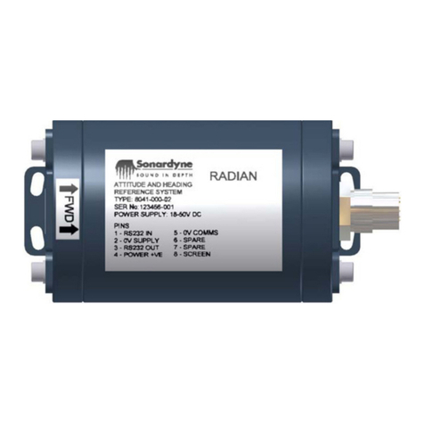
The Lodestar Attitude and
Heading Reference System (AHRS) is an inertial
sensor that provides outputs of roll, pitch, heading, surge, sway and heave
through serial communication links at update rates up to 100 Hz.
The Lodestar AHRS is a robust gyrocompass and, unlike some north-seeking
aided inertial navigation systems, a real-
time input of position is NOT a
prerequisite for basic operation. However, Sonardyne strongly recommends the
Lodestar is supplied with real-time Latitude and velocity compensation data from
a GPS in circumstances where significant changes in Latitude
or velocity can
occur.

Lodestar AHRS
Operation Manual
Document Ref: UM-8084-107-A
6
Issue: A –
Rev 6
© Sona
rdyne International Limited 2013
7
3 Output and Alignment
3.1 Lodestar Output and Alignment
The Lodestar frame convention is described in Figure 1. Unless otherwise stated
for a particular output telegram (see AHRS Messages Specification UM-8084-109
A1 for further details). The Lodestar will output measurements with respect to this
frame. Lodestar angular outputs are defined in Gravity (or Datawell) angles; see
Appendix A for further details.
Before installing the Lodestar it is important to understand the concept of the
vehicle reference frame. Often the chosen centre of a vehicle’s reference frame is
its centre of motion or mass and is usually defined and documented prior to the
installation of equipment such as the
Lodestar. The centre of the vehicle’s
reference frame is often referred to as the central reference point (CRP).
For most applications measurements are required with respect to the vehicle’s
reference frame. The definition of the Lodestar reference frame with respect to a
vehicle is shown in Figure 1.
Figure 1 – Lodestar Reference Frame
The Lodestar frame is a fixed right-hand coordinate frame X Y Z. Typically
Lodestar is mounted so the X axis
is approximately coincident with vehicle
forward; the Y axis is coincident with vehicle starboard; and the Z axis is
coincident with vehicle down. Lodestar has the X and Y directions displayed on
the top of the unit as an orientation aid during installation
. Additionally, all
measurements involving the Lodestar should be made with respect to the unit’s
centre of axis (see Lodestar Hardware Manual UM-8084-101).
In a typical installation, the
Lodestar may not be perfectly aligned to the
installation vehicle reference frame. In certain scenarios, this misalignment may
not need to be corrected within the Lodestar, such as when using Sonardyne’s
CASIUS procedure which will calibrate external sensors used for USBL
positioning.

Lodestar AHRS
Operation Manual
Document Ref: UM-8084-107-A
6
Issue: A –
Rev 6
© Sona
rdyne International Limited 2013
8
Detailed explanations of the effect of misalignment are described in Appendix B.
Methods for measuring fine misalignments of the Lodestar are described in
Appendix C.
Should there be a need; the Lodestar can be configured to compensate small or
large mechanical misalignments as described below.
Mounting
angles
In some cases, for the Lodestar to output measurements that are correct for the
vehicle reference frame, mounting angles in the three axe
s must be carefully
measured and configured
The rotation sequence from a reference frame (vehicle) to the actual Lodestar
frame is:
1. Rotation by the gamma (heading) angle about the Z axis of the reference
frame.
2. Rotation by the beta (pitch) angle about the resulting Y axis.
3. Rotation by the alpha (roll) angle about the resulting X axis.
CAUTION
Only the misalignment for angle C (heading) can be measured
independently. As explained above, the misalignments for
angles B (pitch) and A (roll) are the resultant misalignments
after the preceding misalignments have been applied.
Misalignment angles are specified as Euler angles; see Appendix A for further
details.
The convention for measuring each misalignment angle is shown in
Figure 2, Figure 3 and Figure 4.
Note: - To simplify the definition and convention of each misalignment angle, each angle
is depicted independently but in practice they are non-
commutative and must be
measured in the order defined previously.

Lodestar AHRS
Operation Manual
Document Ref: UM-8084-107-A
6
Issue: A –
Rev 6
© Sona
rdyne International Limited 2013
9
Figure 2 – Lodestar Mounting Angle Gamma (Heading) Example
Figure 3 – Lodestar Mounting Angle Beta (Pitch) Example
Figure 4 – Lodestar Mounting Angle Alpha (Roll) Example1
1Vessel view is ‘bow-on’

Lodestar AHRS
Operation Manual
Document Ref: UM-8084-107-A
6
Issue: A –
Rev 6
© Sona
rdyne International Limited 2013
10
Large
Mounting
Angles
In some cases, the Lodestar may be mounted with a large misalignment, e.g.
horizontally.
In the example shown in Figure 5the Lodestar is to be mounted horizontally on an
ROV. The Lodestar has been pitched forward 90 degrees to be mounted
horizontally; the X axis marking on the top of the Subsea Lodestar
is now
coincident with the Z axis of the vehicle’s frame, pointing in the down direction. If
no other rotations have been applied the resulting misalignment is -90° for
misalignment angle B.
Figure 5 – Example ROV mounting of Subsea Lodestar

Lodestar AHRS
Operation Manual
Document Ref: UM-8084-107-A
6
Issue: A –
Rev 6
© Sona
rdyne International Limited 2013
11
Heave, Surge
and Sway
The heave, or vertical motion of the vehicle in the Earth up direction, is
determined by the double integration of the vertical acceleration. A high pass filter
is used to zero the systematic
biases of the vertical position, which are a
characteristic of the internal sensors. Similarly, the horizontal motions of the
vehicle with zero mean in the X and Y axes respectively are surge and sway.
Heave is output with respect to the earth frame, rather than the vehicle frame, see
Figure 6.
Figure 6 – Lodestar Heave Definition
Remote Heave
Some instruments on the vehicle may require heave compensation. It is likely that
few, if any, of these instruments are installed very close to the centre of the
vehicle frame, and so measurements of heave with respect to the vehicle CRP or
the Lodestar may not be valid for those instruments.
If the Lodestar has information about the offset distances to a remote instrument,
then it can calculate and supply measurements of remote heave for that
instrument using remote vectors. The remote output will resemble what would be
output if the Lodestar was installed in the remote location. Note that the closer to
the remote location the Lodestar is situated, the more accurate the output will be.
The location of the remote point relative to the CRP must be measured in the
vehicle axes pictured in Figure 1.

Lodestar AHRS
Operation Manual
Document Ref: UM-8084-107-A
6
Issue: A –
Rev 6
© Sona
rdyne International Limited 2013
12
Remote
Outputs
As with remote heave output the Lodestar can support other measurement
outputs for remote points for selected telegrams.
A remote point can be specified as offset distances and angular misalignments
with respect to the centre of the vehicle reference frame (CRP) in the following
order.
1. Offset distances (X, Y and Z)
2. Misalignment Angles (A, B and C)
GPS Antenna
The GPS antenna offset must be measured from the centre of the vehicle
reference frame (CRP) to the phase centre of the antenna.
Settling
Measurements of heading require the Lodestar firmware to identify the earth
rotation, which it uses to determine the true north direction. This process does not
happen instantaneously and the Lodestar’s heading output does not achieve the
accuracy quoted for it until the necessary settling time has elapsed.
Note: - The vessel does not need to be stationary during the short settling time.

Lodestar AHRS
Operation Manual
Document Ref: UM-8084-107-A
6
Issue: A –
Rev 6
© Sona
rdyne International Limited 2013
13
4 Installation Preparation
4.1 Installation Preparation
Supplied items
Shipments of the surface Lodestar include the following items as standard:
1 × Console test cableCPN 820-0057
1 × Comms test cableCPN 820-0061
1 ×Console cable tail CPN 820-0054
2 ×Comms cable tails CPN 820-0096
2 ×Transceiver cable tails CPN 820-0062
1 × Drilling template CPN 998-0138
1 ×Laminated quick start guide sheet
1 × Installation disk with Lodestar Configuration Software and manuals
CPN 620-7214
Shipments of the Subsea Lodestar include the following items as standard:
1 × Console test cableCPN 820-0067
1 × Comms (C1) test cableCPN 820-0070
1 × Console cable tail CPN 317-5383
2 ×Comms cable tails CPN 317-5384
2 ×Transceiver cable tails CPN 317-5404
1 × Drillin g te m p la te CPN 998-0137
1 ×Laminated quick start guide sheet
1 × Installation disk with Lodestar Configuration Software and manuals
CPN 620-7214
Configuration
requirements
The following items are required to help configure the Lodestar AHRS:
•A computer with two serial ports running windows XP
•The Lodestar Hardware manual (UM-8084-101)
•The Lodestar AHRS Messages Specification (UM-8084-109)
•The Lodestar Configuration Software
•Lodestar test cables
Configuration
requirements
The following information will be required to complete the installation of Lodestar
•Lodestar mounting angles with respect to the vehicle frame
•Output requirements
•Remote heave offsets or output points with respect to the vehicle frame
•GPS input (optional in some scenarios, see below)
•GPS offsets with respect to the vehicle frame
GPS Input
The Lodestar requires real-time NMEA 0183 telegrams, derived from GPS, to
compensate for changes in Latitude and velocity.
The NMEA GPGGA and GPVTG sentence formats pr
ovide the necessary
information and should be supplied to Lodestar through an IEC 61162 compliant
RS232 serial link, using an update rate of at least 1 Hz and preferably more than
5 Hz.
Note: - In some scenarios it may not be possible to supply a GPS input to Lodestar (e.g.
mounting on a Subsea vehicle). In this case, it is important that the operating Latitude is

Lodestar AHRS
Operation Manual
Document Ref: UM-8084-107-A
6
Issue: A –
Rev 6
© Sona
rdyne International Limited 2013
14
set manually. The process for configuring the Latitude is described later in this document.
GPS Offset
The GPS offset is the distance from the centre of the reference frame to the
phase centre of the GPS antenna. The offset consists of three measurements
taken in the vessel’s forward, starboard and up frames, with the distances
measured from vehicle CRP to the GPS antenna.
A survey of the vehicle should generate accurate drawings of the vessel with
reference points clearly visible.
•If a survey has been scheduled for the near future, it should include the
Lodestar and the information concerning the Lodestar’s location in the vessel
should be made available to the installation engineer.
•If a survey has already taken place and does not include Lodestar, then the
most up-to-date drawings available will be required.

Lodestar AHRS
Operation Manual
Document Ref: UM-8084-107-A
6
Issue: A –
Rev 6
© Sona
rdyne International Limited 2013
15
5 Installation and Physical Configuration
5.1 Typical Lodestar AHRS configuration
This Installation Manual is intended to accompany the Lodestar training courses
run by Sonardyne International Limited, but it can also be used in isolation or as a
source of reference information. It has been written primarily as a guide for field
engineers who have been given the task of installing either a surface or a subsea
version of the Lodestar AHRS on board a vessel.
Surface
Lodestar
Figure 7 shows an example of a typical installation for the surface Lodestar.
Figure 7 – Typical Installation of the surface Lodestar
In the example shown:
•Console Port is the command port
and has its output communication
parameters fixed on 9600-8-N-1. This port is connected to a PC running the
Lodestar Configuration Software.
•RSXXX_1 is the primary output port on the surface varia
nt. This port is
connected to the navigation system.
•RSXXX_2 is connected to a GPS receiver.
•Ethernet connection is optional but can be used to configure and send/receive
data to or from the Lodestar.

Lodestar AHRS
Operation Manual
Document Ref: UM-8084-107-A
6
Issue: A –
Rev 6
© Sona
rdyne International Limited 2013
16
Subsea
Lodestar
Figure 8 shows an example of a typical installation for the subsea Lodestar.
Figure 8 – Typical Installation of the subsea Lodestar
In the example shown:
•Console Port is the command port
and has its output communication
parameters fixed on 9600-8-N-1. This port is connected to a PC running the
Lodestar Configuration Software.
•C1 Port is the primary output port on the Subsea
variant. This port is
connected to the navigation system.
•T1 Port can be connected to a GPS receiver if possible (for example when
using the system with a multi-beam or USBL when the Subsea Lodestar is
not at depth).
•T2 is another output port RS232 or RS485, and is not used in the example
shown.
•E1 (C2 on old units) Port provides Ethernet connection, which is optional but
can be used to configure and send/receive data to or from the Lodestar

Lodestar AHRS
Operation Manual
Document Ref: UM-8084-107-A
6
Issue: A –
Rev 6
© Sona
rdyne International Limited 2013
17
5.2 Installation
Important:
•The unit must be secured.
•A Surface Lodestar must be connected to Earth.
Physical
installation
The Lodestar mounting bracket has reference dowels to make sure the Lodestar
mounting position is repeatable.
If the Lodestar mounting bracket is not used for some reason, do not disturb or
remove the Lodestar from its installed location after measuring
the mounting
angles and offsets. If removed or disturbed then the misalignment is void.
Connect all the cables to be used for the installation. Note the Console cable is
different from the communications and transceiver cables. Do not mix these
cables. The cables are keyed differently and colour coded. For
Subsea and
Surface units, a Red cable is for the console port, Yellow is for comms ports and
Blue is for Transceiver ports. For the Subsea unit, the Ethernet cable is colour
coded green.
Further guidance on Lodestar installation and physical configuration can be found
in Lodestar Hardware manual (UM-8084-101)

Lodestar AHRS
Operation Manual
Document Ref: UM-8084-107-A
6
Issue: A –
Rev 6
© Sona
rdyne International Limited 2013
18
6 Configuration using Lodestar PC Utility
6.1 Installation and Connection
Installation
1. Close all applications running on the PC and insert the Lodestar Software CD
into the CD/DVD drive.
2. Browse to the drive using Windows Explorer and use the left mouse button to
double-click the drive.
3. The disk installs the Lodestar Software and manuals automatically, follow the
on-screen instructions.
4. Once installed, the Lodestar PC Utility runs.
Connection to
PC
1. Connect the PC to the Lodestar via a serial port on the PC or alternatively an
Ethernet connection and switch on Lodestar.
Note: - Connection to the Lodestar can be made via serial or Ethernet ports.
Serial Port:
The software will default to COM 1 on the PC
Ethernet Port:
The Lodestar default Ethernet properties are:
•IP Address: 192.168.179.50
•Subnet Mask: 255.255.255.0
•Command port/socket: 4000
The software will default to these values if the Ethernet
options is
chosen. Make sure the PC Ethernet port is configured correctly to allow
communication with the Lodestar’s default settings.
The method for
changing the Lodestar Ethernet’s
settings is explained later in this
manual.
2. If Lodestar is being used as a stand alone AHRS then connect GPS to the
Lodestar using a spare IO port
and arrange to supply the NMEA 0183
$GPGGA and $GPVTG sentences to the Lodestar.
Note: - See section 5.1 for some example connection configurations.
3. Connect the Lodestar’s IO ports to the external instrumentation as required.
4. Start the Lodestar Configuration Software if it is not already running by double
clicking the program’s icon on the PC’s desktop.

Lodestar AHRS
Operation Manual
Document Ref: UM-8084-107-A
6
Issue: A –
Rev 6
© Sona
rdyne International Limited 2013
19
6.2 System
Connect to
the
Lodestar
Once a physical connection has been made it is necessary to tell the PC Utility to
communicate with Lodestar; see Figure 9.
Figure 9 – Configuration Software Main Window (not connected)
Configure the connection to the Lodestar by pressing the ‘Connect’ button. The
application will default to a serial connection on PC port COM 1 as shown in Figure 10.
Figure 10 – Lodestar Serial Connection Settings
To configure an Ethernet or NSH connection, press the ‘IP’ button and the default
Lodestar Ethernet connection parameters are displayed, as shown in
Figure 11.

Lodestar AHRS
Operation Manual
Document Ref: UM-8084-107-A
6
Issue: A –
Rev 6
© Sona
rdyne International Limited 2013
20
Figure 11 – Lodestar Ethernet Connection Settings
Note: - Before proceeding make sure the Lodestar has been running for at least 1 minute
before trying to connect via the configuration software. This allows time for the Lodestar to start
up and receive commands (see Lodestar Hardware Manual UM-8084-101 for more details)
Once the connection parameters match the physical connection between the Lodestar
and the PC, press the ‘OK’ button.
A window will appear indicating communication status with the Lodestar.
Once connected, the software will populate with the Lodestar configuration and the
status indicator circle on the bottom left hand side of the application will turn green,
indicating a good communication link with the Lodestar; see Figure 12.
Figure 12 – Configuration Software Main Window (connected)
Table of contents
Other Sonardyne Accessories manuals
Popular Accessories manuals by other brands

Interlink electronics
Interlink electronics FSR Integration guide

PCB Piezotronics
PCB Piezotronics M261B01 Installation and operating manual

Yaohua Weighing System
Yaohua Weighing System XK3190-A7 user manual

Chamberlain
Chamberlain 771ANZ user manual

Iget
Iget SECURITY M3P9 installation manual

SBG
SBG ELLIPSE Series quick start guide