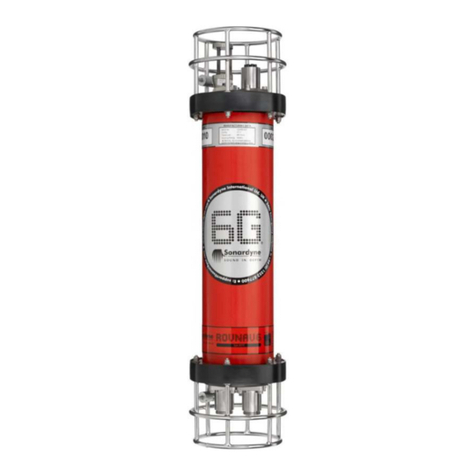
Sonardyne 8142-000-01 User manual

UM-8142/8182
Revision Number: Initial Issue
Prepared by: Edmund Ceurstemont
Authorised by: Darryl Newborough
Issue Date: 20/12/2010
Commercial in Confidence
This document contains Sonardyne
Technical information and is issued
Commercial in Confidence.
The contents of this document must not
be divulged to any third party without
Sonardyne’s written permission
User Manual for:
Type 8142-000-01/02 USBL Transceivers
Type 8182-000-01 Modem/transceiver
Sonardyne Wideband2®
6 Generation (6G®)
Issuing Office
Sonardyne International Limited T. +44 (0) 1252 872288
Blackbushe Business Park F. +44 (0) 1252 876100
GU46 6GD United Kingdom Sonardyne International Ltd.

Initial Issue
Issue Date 25/06/2010
User Manual: 8142/8182 Transceivers
Table of Contents 0-1
Page 1of 5
TABLE OF CONTENTS 0-1
Section Subject
01 Preliminaries
Table of Contents 0-1
Customer Change Request Form (CCRF) 0-2
Record of Revisions 0-3
Introduction 0-4
1 - General
2 - Observance of the User Manual
3 - Warranty
4 - How to Use this User Manual
5 – Units of Measurement
6 - Verification
7 – Glossary of Terms
8 – General Safety Precautions
9 – Hazard Appreciation
10 – General Handling of Equipment
11 – Dismantling Sub-sea equipment
11.1 Instruments fitted with Sprung vent Valves
11.2 Precautions (Instrument Fully Functioning)
11.3 Precautions (Instrument known or suspected of being Pressurised)
12 – Instrument Load Bearing Capacity
13 – Floatation Equipment
Head Office
Sonardyne International Limited
Blackbushe Business Park,
Yateley, Hampshire,
GU46 6GD, UK
T. +44 (0) 1252 872288
F. +44 (0) 1252 876100
www.sonardyne.com

Initial Issue
Issue Date 25/06/2010
User Manual: 8142/8182 Transceivers
Table of Contents 0-1
Page 2of 5
02 Technical and Functional Description
1 - General
2 – System Description
2.1 Type 8142 Transceiver
2.2 Type 8182 Transceiver
3 – Acoustic Processing Principles
3.1 Positioning
3.2 Sonardyne Wideband®2 Signals
3.3 Data Exchange
4 – USBL
4.1 ROV/Tow Fish Tracking
4.2 Dynamic Positioning
5 - LUSBL
5.1 Dynamic Positioning
5.2 Underwater Positioning
5.3 Marine Riser Angle Monitoring
03 Technical Data
1 – 8142-000-01 Transceiver and 8182-000-01 Transceiver
1.1 Mechanical
1.2 Electrical
1.3 Acoustics
1.4 Environmental
2 – 8142-000-02 Transceiver
2.1 Mechanical
2.2 Electrical
2.3 Acoustics
2.4 Environmental
04 Operating Instructions
1 – 8142 Transceiver
1.1 Operating Instructions

Initial Issue
Issue Date 25/06/2010
User Manual: 8142/8182 Transceivers
Table of Contents 0-1
Page 3of 5
05 Maintenance and Storage
1 – 8142 Transceivers Clean, Examine and Store
1.1 Tools
1.2 Consumable Materials
1.3 Preparation
1.4 Clean and Examine the Transceiver
1.5 Storage
1.6 Post Task Procedures
2 – Recommended Lubricants
3 - Maintenance Codes and Schedule
06 Fault Finding
1 – No Communication From Transceiver
1.1 Check the Wiring and the Power
1.2 Check AGP Connector
1.3 Check Continuity of RS485 Connection
07 Removal
1 – Removal Transceivers 8142-000-001/2
1.1 Tools and Equipment
1.2 Equipment Weights
1.3 Preparation
1.4 The Method, for removing the transducer from through deck pole or over-
side mount.
08 Operational Test
1 - Testing the Transceiver
09 Repair
1 – No Authorised Repairs
10 Battery Safety
1 – Battery Safety

Initial Issue
Issue Date 25/06/2010
User Manual: 8142/8182 Transceivers
Table of Contents 0-1
Page 4of 5
11 Upgrading Firmware
1 – Upgrade HPT Firmware via Marksman or Ranger 2
2 - Upgrade HPT Firmware via HPT Terminal
12 Installation
1 – Installation Transceivers 8142-000-001/2
1.1 Tools and Equipment
1.2 Equipment Weights
1.3 Consumable Materials
1.4 Preparation
2 – Installation
2.1 Mounting the Transceiver
2.2 Transceiver Interconnections
13 Acoustic Navigation Principle
1 – Acoustic Navigation System Principles
1.1 Long Base Line Principles
1.2 Short Base Line Principles
1..3 Ultra Short Base Line Principles
1.4 Long Ultra Short Base Line Principles
14 Recommended Spares
1 – How to Order Spares
2 – Recommended Spares
2.1 Transceiver 8142-000-001/2
2.2 Assemblies
2.3 Cables
15 Drawings
1 – AGP Tail Stripping Detail
2 – 8 Pin Lemo to Flylead
3 – HPT Outline – 8142-000-01
4 – Serial I/O cable Assembly
5 – HPT Outline – 8142-000-02

Initial Issue
Issue Date 25/06/2010
User Manual: 8142/8182 Transceivers
Table of Contents 0-1
Page 5of 5
16 Deployment
1 – 8142 transceiver Deployment
1.1 Preparation
1.2 Deployment From Ship
17 Equipment Log Book
1 – Deployment and Recovery
2 – Repairs
3 - Servicing
4 – Sea State Table

Initial Issue
Issue Date 25/06/2010
User manual: 8142/8182 Transceivers
Customer Change Request Form 0-2
Page 1of 1
CUSTOMER CHANGE REQUEST FORM 0-2
Use this form to tell Sonardyne Int Ltd of any errors or omissions that you find when you use this manual. Your
request will be acknowledged and Sonardyne Int Ltd will inform you of any action to be taken.
To:Sonardyne Int Ltd
Blackbushe Business Park
Yateley
Hampshire Fax (0) 1252 876100
Publication: Type 8142 USBL Transceivers and Type 8182 transceivers - User Manual
Publication No.: UM 8142/8182
Page Block:_______ Section Title:_________________________ Revision:_____
From: Company: ________________________ Department: ______________________
Name: ___________________________ Title: ____________________________
Address: ______________________________________________________________
______________________________________________________________
Telephone: ________________ Fax: _______________ E-mail: _________________
Comments:
Head Office
Sonardyne International Limited
Blackbushe Business Park,
Yateley, Hampshire,
GU46 6GD, UK
T. +44 (0) 1252 872288
F. +44 (0) 1252 876100
www.sonardyne.com

Initial Issue
Issue Date 25/06/2010
User manual: 8142/8182 Transceivers
Record of Revision 0-3
Page 1of 1
RECORD OF REVISION 0-3
Rev No. Description Page/ Date Inserted By Date
Initial Issue Complete Issue All Sonardyne Int Ltd 20/12/2010
Head Office
Sonardyne International Limited
Blackbushe Business Park,
Yateley, Hampshire,
GU46 6GD, UK
T. +44 (0) 1252 872288
F. +44 (0) 1252 876100
www.sonardyne.com

User Manual: Generic Section
Section: Introduction 0-4
Revision: 00
Page 1 of 21
INTRODUCTION 0-4
Contents
1GENERAL
2OBSERVANCE OF THE USER MANUAL
3WARRANTY
4HOW TO USE THIS USER MANUAL
5UNITS OF MEASUREMENT
6VERIFICATION
7GLOSSARY OF TERMS
8GENERAL SAFETY PRECAUTIONS
9HAZARD APPRECIATION
10 GENERAL HANDLING OF EQUIPMENT
11 DISMANTLING SUB-SEA EQUIPMENT
11.1 INSTRUMENTS FITTED WITH SPRUNG VENT PLUGS
11.2 PRECAUTIONS (INSTRUMENT FULLY FUNCTIONING)
11.3
PRECAUTIONS (INSTRUMENT KNOWN OR SUSPECTED TO BE
PRESSURISED)
12 INSTRUMENT LOAD BEARING CAPABILITY
13 FLOATATION EQUIPMENT
Head Office
Sonardyne International Limited
Blackbushe Business Park,
Yateley, Hampshire,
GU46 6GD, UK
T. +44 (0) 1252 872288
F. +44 (0) 1252 876100
www.sonardyne.com

User Manual: Generic Section
Section: Introduction 0-4
Revision: 00
Page 2 of 21
1 GENERAL
This User Manual is issued by Sonardyne International Limited.
This User Manual contains all the information necessary to operate and maintain the equipment in an
operational environment.
This User Manual contains the technical data, operating instructions, maintenance schedules, maintenance
procedures, spares information and all applicable drawings and parts lists.
This User Manual is divided into the sections that follow:
01 Preliminaries:
Table of Contents 0.1
Customer Change Request Form (CCRF) 0.2
Record of Revisions 0.3
Introduction 0.4
02 Technical and Functional Description
03 Technical Data
04 Operating Instructions
05 Maintenance
06 Fault Finding and Testing
07 Removal
08 Operational Test
09 Repair
10 Battery Safety
11 Upgrading Firmware
12 Installation
13 Acoustic Navigation Principle
14 Spares
15 Drawings and Parts Lists
16 Deployment
17 Equipment Log Book

User Manual: Generic Section
Section: Introduction 0-4
Revision: 00
Page 3 of 21
2 OBSERVANCE OF THE USER MANUAL
This User Manual must only be used by trained and qualified maintenance personnel that are familiar with
the equipment included in this User Manual.
It is the responsibility of the customer, to make sure that all operation and maintenance personnel that will
operate and maintain the equipment included in this User Manual are correctly trained and qualified.
Before you operate or do any work on the equipment you must read and obey all sections of this User
Manual.
You must keep the Equipment Log Book up to date and current.
The procedures and instructions in this User Manual have been provided to maintain the integrity and
serviceability of this equipment only.
You must follow all procedures and instructions in this User Manual as they are given. If you do not follow
the procedures / instructions correctly, you can cause damage to the equipment, its assemblies, components
or parts.
Only the procedures and instructions given in this User Manual have the approval of Sonardyne International
Limited. If a necessary procedure or instruction is not given in this User Manual, before you continue you
must contact Sonardyne International Limited.
Only the parts given in this User Manual have the approval of Sonardyne International Limited.
You must read and obey all WARNINGS and CAUTIONS given in this User Manual.
For all consumable materials you must also read and obey the manufacturers’ health and safety instructions.
If the WARNINGS and CAUTIONS given in this User Manual are different to those given by the
manufacturer, you must obey those given by the manufacturer.
All operations and work done on this equipment must be done in accordance with the local health and safety
and environmental regulations and the safe working practices of the applicable site, installation or
operational environment.

User Manual: Generic Section
Section: Introduction 0-4
Revision: 00
Page 4 of 21
3 WARRANTY
Sonardyne International Ltd warrants, subject to the following conditions, upon the return of the goods to its
works or with prior approval to a local agent, carriage paid, to examine it or them and should any fault due to
defective design, material or workmanship be found, to repair the defective part or parts or, at its own
discretion, to supply a new part or parts in place of the same free-of-charge.
Any claim under this warranty must be lodged in writing with Sonardyne within twelve months and the part or
parts returned to Sonardyne within thirteen months of the commencement of the warranty. The warranty will
commence upon the commissioning or putting into service of the equipment or one month from shipment
from Sonardyne, whichever is the sooner.
No claim can be accepted for damage due to fair wear and tear, misuse, neglect, dirt, accident, overloading,
or other similar causes, and Sonardyne International Ltd judgement in all matters relating to claim shall be
final and conclusive and the buyer agrees to accept Sonardyne International Ltd decision on all questions as
to defects and as to the exchange of any part or parts.
Goods supplied to buyer's drawings or designs are not warranted by Sonardyne International Ltd to be fit for
any particular purpose.
The foregoing warranty is rendered void in any of the following circumstances:
a) If any seal, safety device, identification, or instruction plates are deliberately broken or removed
from the goods.
b) If any pressure housing has been opened.
c) If the goods are worked beyond their rated capacity.
d) If any parts or accessories other than those approved by Sonardyne International Ltd, have
been fitted to the goods.
These contractual warranties are in addition to and shall not be construed to modify or limit in any manner
any rights or actions which the buyer may otherwise have against Sonardyne by law or statue, or in equity.
In the event that agreement cannot be reached the matter will be placed in the hands of an independent
arbitrator appointed by the London Chamber of Commerce whose decision shall be binding on both parties.

User Manual: Generic Section
Section: Introduction 0-4
Revision: 00
Page 5 of 21
4 HOW TO USE THIS USER MANUAL
Look on the Title page. Make sure this User Manual is applicable to the equipment that you will operate and
do work on.
Use the Table of Contents (TOC) to find the applicable section of the User Manual.
Use the applicable sections of this User Manual to do the necessary task.
Before you start a task, read and obey the applicable WARNINGS and CAUTIONS.
To find the applicable part of an assembly or component, refer to Section 14 – Spares.
This User Manual is designed so that you can remove separate sections to make a copy to help you do the
task. You must make sure that you return any section or part of the User Manual that you remove.
You must keep this User Manual clean, readable and complete.
You must tell Sonardyne International Limited of any errors that you find when you use this User Manual.
The content of each section of the User Manual is described in the following paragraphs:
Technical and Functional Description Para.3.1
Technical Data Para.3.2
Operating Instructions Para.3.3
Maintenance Para.3.4
Fault Finding and Testing Para.3.5
Removal Para.3.6
Repairs Para.3.7
Installation Para.3.8
Spares Para.3.9
Drawings and Parts Lists Para.3.10
Appendices Para.3.11

User Manual: Generic Section
Section: Introduction 0-4
Revision: 00
Page 6 of 21
3.1 Technical and Functional Description
Description of the assemblies that make up the equipment and how they operate.
3.2 Technical data
All the equipment Specifications included in the User Manual.
3.3 Operating instructions
This section gives the information necessary to operate the equipment.
3.4 Maintenance
This section gives all the necessary information to maintain the equipment. It includes the
recommended lubricants, maintenance codes, schedules and maintenance tasks. The maintenance
section also includes any applicable inspections or adjustments. The maintenance tasks do not
include any schedule or frequency information.
3.5 Fault Finding and Testing
This section gives the necessary information for the purpose of identifying faults with the equipment. It
also includes any necessary functional tests of equipment with test equipment.
3.6 Removal
This section gives the necessary procedures to remove the equipment, assemblies, sub-assemblies or
components for the purpose of maintaining the equipment.
3.7 Repairs
This section includes any applicable repair procedures necessary to return the equipment to a
serviceable condition.
3.8 Installation
This section gives the necessary procedures to install the components,
sub-assemblies, assemblies and equipment, for the purpose of maintaining the equipment.
3.9 Spares
This section gives the recommended spares necessary to operate the equipment in addition to a
detailed list of all the replaceable parts installed on the equipment.
3.10 Drawings and Parts Lists
This section gives all the drawings and Parts Lists applicable to the equipment.
3.11 Appendices
This section gives any additional information that is a supplement to the User Manual, but may be
necessary to operate and maintain the equipment.

User Manual: Generic Section
Section: Introduction 0-4
Revision: 00
Page 7 of 21
5 UNITS OF MEASUREMENT
All dimensions, weights, pressure, torque values, etc. in the User Manual are normally given in metric units.
But, when required they will be followed by imperial units in parentheses.
6 VERIFICATION
All technical data, descriptive, operational and procedural information given in this User Manual has been
approved by Sonardyne International Limited.
7 GLOSSARY OF TERMS
NOTE: The terms that follow are general and are not specific to this User Manual.
NOTE: The table that follows contains User Operator Terms, Sonardyne Systems, Signal Processing and
Communication Terms and General Terms.
User Operator Terms
Term Definition
Acoustic Transceiver An instrument that emits acoustic signals and receive acoustic
signals and extract information from them. Transceivers can
measure the time it takes a signal to travel from its transducer
to a transponder and return. Some can encode and send data
in a message and extract digital data from a message
(Acoustic Telemetry). Used on a surface vessel or to mark a
point on the seabed, or fixed to a mobile for tracking or
positioning.
Acoustic Transponder An instrument that emits an acoustic signal when it detects an
interrogating acoustic signal.
Acoustic Responder An instrument that emits an acoustic signal in response to an
electrical signal carried to it by cable
Acoustic Synchronous/ Precision Pinger An instrument that emits signals regularly without an
interrogating signal. A SYNCHRONOUS Pinger can be
synchronised to an external master signal.
A PRECISION Pinger has an accurate internal time standard
Acoustic Transducer A device that converts electrical signals into acoustic signals
and vice-versa

User Manual: Generic Section
Section: Introduction 0-4
Revision: 00
Page 8 of 21
User Operator Terms
Term Definition
Acoustic Transponder (Intelligent
Transponder)
A type of transponder that is managed by a micro-controller.
Examples include the COMPATT (COMPuting And Telemetry
Transponder) and the WMT (Wideband Mini Transponder).
Depending on supported functionality it can:
Decode acoustic telemetered commands from a transceiver
and can send telemetered data to the transceiver. It can
measure the distance between itself and other transponders
and then telemeter the data to a transceiver. It can be capable
of measuring its depth and the temperature of the water.
It can be used to measure a variety of underwater parameters
and telemeter these back to the surface. It can be used, as an
intelligent angle-measuring device, in a Riser Angle Monitoring
System.
It can be fitted with a release mechanism so it can return, on
command, back to the surface e.g. if battery power is low.
Acoustic Signal Information carried by sound pressure waves through water.
The Sonardyne acoustic signal has a finite length
Common Reply Signal (CRS) A reply signal common to a complete family of addressed
transponders.
COMPATT COMPuting And Telemetry Transponder (see Acoustic
Intelligent Transponder).
Data Acquisition Sub-Assembly (DAS) A micro – controlled data acquisition and logging sub assembly
located within a transponder.
Database A body of data stored in a computer memory, magnetic disc
media e.g. embedded hard disc or portable floppy disc
Data Fusion Engine (DFE) Acts as the system controller, generates the display signals for
the monitor, processes the data from the transceiver for the
display to the operator and output to a DP system and talks to
various "attitude" sensors and other navigation systems
Differential Global Positioning System
(DGPS)
A 24 hour, world-wide radio navigation system. GPS receivers
track and decode the data from satellites and calculate the
position and speed of a vehicle.

User Manual: Generic Section
Section: Introduction 0-4
Revision: 00
Page 9 of 21
User Operator Terms
Term Definition
Digital Signal Processing (DSP) The representation of signals by a sequence of numbers or
symbols and the processing of these signals. DSP includes
subfields like: audio and speech signal processing, sonar and
radar signal processing, sensor array processing.
Dynamic Positioning System (DPS) Automatically maintains a vessel with a constant heading, and
in a fixed position without an anchor and provides more
flexibility in operation
Dynamic Positioning reference (DP
Reference)
Several position inputs e.g. GPS receivers, taut wire sensors,
LBL, SBL or USBL acoustic positioning sensors, wind speed
indicators etc
Dynamic Positioning telegram (DP
Telegram)
The report an acoustic positioning system sends to a DP
system over a serial interface
Geodetic Co-ordinates The position of any point on or near the earth surface is defined
by an angle of latitude and an angle of longitude.
For a point on earth P:
Latitude is defined as the angle between the normal plane at P
and the plane of the earth’s equator.
Longitude is defined as the angles between the meridians
plane through P and the defined zero meridian plane or
"Greenwich" plane.
(Ref. Geodesy, fourth edition, Bomford, Oxford, sections 2.03
and 4.10(d)).
Gyro Compass A gyro compass is similar to a gyroscope. It is a compass that
finds true north by using an (electrically powered) fast-spinning
wheel and friction forces in order to exploit the rotation of the
Earth. Gyro compasses are widely used on ships. They have
two main advantages over magnetic compasses:
They find true north, i.e., the direction of Earth's rotational axis,
as opposed to magnetic north.
They are far less susceptible to external magnetic fields, e.g.
those created by ferrous metal in a ship's hull.
Inclinometer An analogue device, which measures the angle of the
transponder.
Individual Interrogation Signal (IIS) Signal used to uniquely address a transponder, based on the
transponders acoustic address.
Individual Reply Signal (IRS) Signal used to uniquely identify a reply from a transponder.
Mobile An object that can move freely between the seabed and the
sea surface.

User Manual: Generic Section
Section: Introduction 0-4
Revision: 00
Page 10 of 21
User Operator Terms
Term Definition
Monitor/Keypad A monitor contains a 12 inch colour graphics display and has a
keypad for operator input.
A later version of this unit has a 17 inch high resolution
monitor. The monitor and keypad are split into two separate
units. Both are designed for 19 inch rack mounting
Marine Riser Angle Monitoring System
(MRAMS)
Used for measuring the angle between the Blow-Out Preventer
(BOP) on the seabed and the Riser.
Navigation Sensor Hub (NSH) The NSH is the interface between the in-water acoustic
instruments, sensors and the Navigation Computer which runs
the acoustics positioning software.
Remotely Operated Vehicle (ROV) A vehicle controlled and powered by a cable connection so it
can travel between the sea surface and the seabed
Heading, Roll and Pitch (HRP) Is a compensated vessel frame. This is a frame sharing the
same origin as the vessel frame but with the z axis vertical and
the y axis parallel with a meridian passing through the origin
(points true north)
Seabed The surface of the earth covered by sea water. The seabed is
considered stationary
Spread Spectrum (SS) Spread-spectrum techniques are methods by which a signal
(e.g. an electrical, electromagnetic, or acoustic signal)
generated in a particular bandwidth is deliberately spread in the
frequency domain, resulting in a signal with a wider bandwidth.
These techniques are used for a variety of reasons, including
the establishment of secure communications, increasing
resistance to natural interference and jamming, to prevent
detection, and to limit power flux density.
Unit Identification Number (UID) Each product produced by Sonardyne Int Ltd contains a unique
24bit address. It is denoted by 6 hexadecimal characters.
Wideband Test Terminal (WTT) PC software for testing 6G transponders and transceivers.
Sonardyne Wideband®2 6G® transponders and transceivers use Sonardyne
Wideband® 2 which has ultra-wide bandwidth signals giving a
faster and robust transmission of data, more precise ranging
and mitigation from multipath in shallow water and amongst
steel structures in deepwater.
6 Generation (6G®) 6G® technology gives a better performance, easier to use,
more functions, equipment flexibility and compatibility with
aided inertial technologies.

User Manual: Generic Section
Section: Introduction 0-4
Revision: 00
Page 11 of 21
Sonardyne Systems
Term Definition
Long-Base-Line (LBL) System A system where two or more transponders are on the seabed.
The positions of the transponders are established by a
calibration process in a seabed frame.
The distances from a transducer to each transponder are
measured using a transceiver.
The position of the transducer can be computed in the seabed
frame.
The name comes from the "baselines" joining each
transponder. It is can be to as a range-range system
Short-Base-Line (SBL) System A system where three or more transducers are fixed to a vessel
and connected to a single transceiver.
The position of each transducer is measured and co-ordinated
in the vessel frame. By measuring the time of arrival of the
signal from a transceiver at each transducer the position of the
transceiver in the vessel frame can be computed.
Ultra-Short-Base-Line (USBL) System A system similar to an SBL system except the system uses
three or more elements in a single transducer array.
The measurements it makes are the differences in "time-
phase" of the signals from each element.
The co-ordinate frame is fixed to the transducer array which
must be oriented in the vessel frame to be equivalent to the
SBL system.
Long-Ultra-Short-Base-Line (LUSBL)
system
A hybrid of an LBL and a USBL system. It utilises USBL
equipment in an LBL configuration.
Dual-Redundant LUSBL System Two complete sets of LUSBL equipment working in tandem on
a master/slave basis.
The two sub-systems are cross-linked so that, in the event of a
failure of any major elements, system operation will continue
without the need for operator intervention.
Operation of the dual-redundant version is identical to that of
the standard version.
EHF Extra-High Frequency (50-110kHz)
HF High Frequency (35-55kHz)
LF Low Frequency (7.5-15kHz)
LMF Low-Medium Frequency (13-17kHz)
MF Medium Frequency (18-36kHz)
Sound Speed If seawater is at a constant temperature, salinity and pressure
the speed at which sound travels in seawater is constant.
Sound speed can be derived from values of conductivity,
temperature and depth, or it can be measured directly using
time-of-flight instruments.

User Manual: Generic Section
Section: Introduction 0-4
Revision: 00
Page 12 of 21
Sonardyne Systems
Term Definition
Sound Speed Profile At different depths the temperature, salinity and pressure vary,
so the local sound speed varies.
Depth cannot be measured directly. So pressure
measurements are taken, and the depth calculated, using
knowledge of density and local gravity. Derivation of density
requires knowledge of temperature and salinity. Salinity cannot
be measured directly but conductivity can be measured.
A method of measuring the sound speed profile is from a
profile of pressure, temperature and conductivity and a formula
to compute depth and sound speed.
Submersible A vehicle that operates below the seas surface.
It can carry men in a one atmosphere environment with one
man piloting the craft.
It has a supply of air for the crew and a supply power for
propulsion etc. It can operate autonomously form a vessel for
a limited time.
True North The direction of the shortest line that can be drawn, across the
surface of the earth, from the observer and the north pole.
(The north pole is where the north end of the spin axis of the
earth meets the surface.)
Universal Transverse Mercator (UTM) A Projection system that is used to transform Geodetic co-
ordinates into an orthogonal two dimensional system suitable
for representation on a plane such as a chart. The co-ordinates
are called easting and northing which are equivalent to x and y
respectively. The UTM system is a world wide system.
Each projection covers 6 degrees of longitude with the central
meridian at 3, 9 degrees etc east of Greenwich and from 84
degrees north to 80 degrees south. The scale factor on a
central meridian is 0.9996 (with some exceptions).
The projection is orthomorphic this means at a point the scale
in all directions is the same there is no local distortion. NOTE:
Scale factors change with distance from the central meridian.
For points away from the central meridian grid north and true
north diverge. The difference is called the CONVERGENCE
which is positive when grid north is east of true north. The point
where the central meridian meets the spheroid equator is given
a false easting of 500,000 m. Many countries’ mapping
systems are based on the same system but use a particular
reference spheroid.
This manual suits for next models
2
Table of contents
Other Sonardyne Transceiver manuals
Popular Transceiver manuals by other brands

Technisonic Industries Limited
Technisonic Industries Limited TiL-91-DE/8.33 Installation and operating instructions
Kenwood
Kenwood NX-1200NE2 user manual
Allied Telesis
Allied Telesis CentreCOM AT-200 Series user manual
Kenwood
Kenwood TM-V71E Service manual
Standard Horizon
Standard Horizon HX260S owner's manual
WAGO
WAGO I/O-SYSTEM 750 manual
