Sonardyne 6G ROVNAV 6 User manual
QUICK START GUIDEROVNAV 6INSTALLATION GUIDETo access more information on the ROVNav 6, download a free QR code app on your Smartphone and then scan this code.
QSG-IG-8310-A108/2013910-0003
SAFETYIt is recommended the operator complies with the Health and Safety Regulations applicable to the vessel and the region before operating this equipment.If the equipment is used in a manner not specified by the manufacturer, the protection provided by the equipment may be impaired.Documentation must be consulted whenever the warning symbol is found on the equipment, in order to find out the nature of the potential hazard and any actions which must be taken.The ROVNav 6 weighs 13 kg, Manual Handling Equipment (MHE) must be used to move the transceivers. If MHE is not available, then a manual handling assessment must be carried out prior to carrying out manual lifting / handling. Make sure Personal Protective Equipment such as protective footwear and gloves are worn before lifting this equipment.Electric shock hazard risk if the Remote Transducer output connector contacts are touched whilst the transducer cable is disconnected, the unit is powered and if instructed to transmit. Never touch the connector contacts whilst the power is on.High pressure risk when dismantling the equipment. Dismantling the sub-sea equipment must only be carried out by trained personnel.Do not stand in direct line with the end of the ROVNav 6 when operating the Pressure Relief Valve. Sudden release of high pressure gases from the ROVNav 6 could cause injury to personnel. Wear Personal Protective Equipment such as goggles when operating the Pressure Relief Vent Valve.Make sure the Pressure Relief Vent Valve is manually operated, in a well ventilated area, to release any internal pressure before attempting to remove the end-cap. Electric shock hazard risk is present when dismantling the equipment. High voltages are present inside the ROVNav 6. Dismantling the equipment must only be carried out by trained personnel. WARNINGSPRODUCT SUPPORTEmail: [email protected]Tel: +44 (0) 1252 872288Should you require NON-EMERGENCY product support for your ROVNav 6, email and telephone product support is available during normal UK office hours (08:00-17:00). Alternatively, please contact your nearest Sonardyne Office. Visit www.sonardyne.com for full details.In emergency situations, the Sonardyne 24 hour helpline is answered during normal office hours - 08:00-17:00. Outside these hours, your call is automatically transferred to an agency who will log the details of your emergency and alert the appropriate Sonardyne personnel. Our aim is to ensure that emergency requests are dealt with immediately during office hours and are responded to within 30 minutes at all other times.SONARDYNE 24HR EMERGENCY HELPLINE: UK +44 (0) 1252 877600 STEP 1
EQUIPMENT SUPPLIEDSTEP 2
1
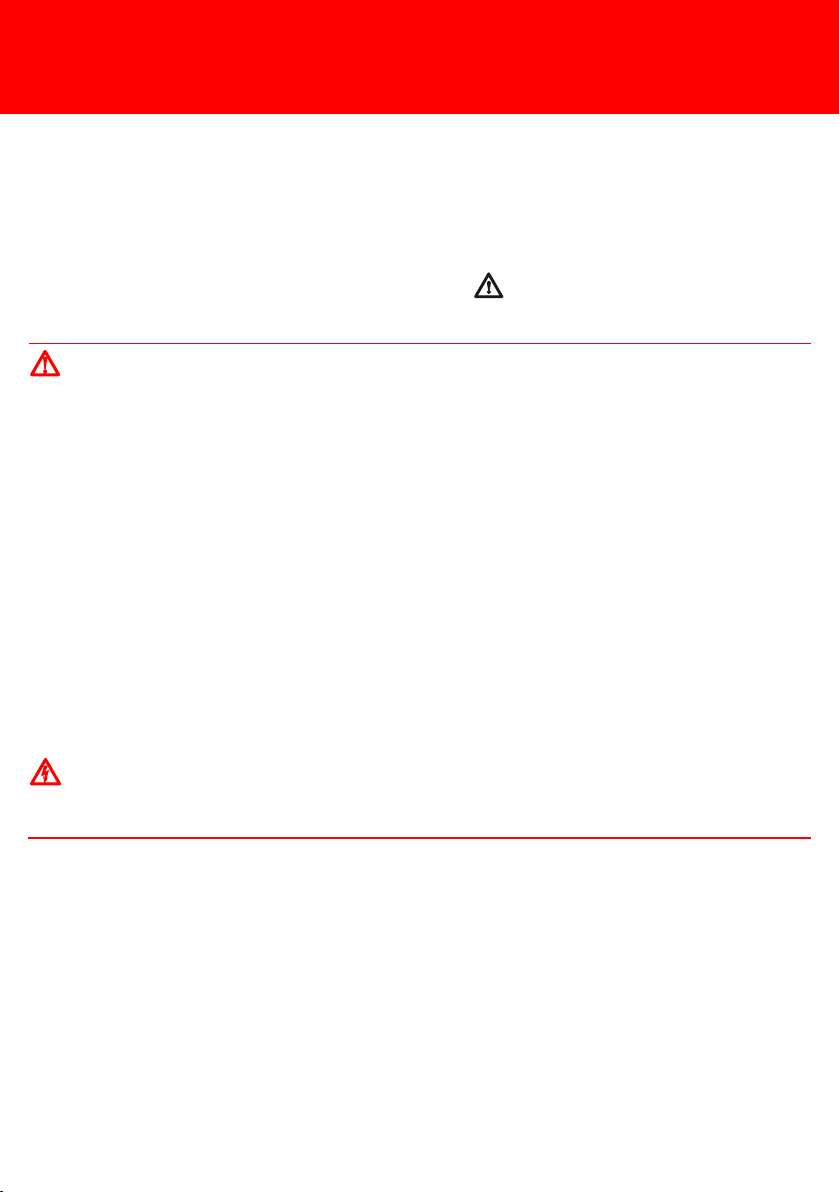
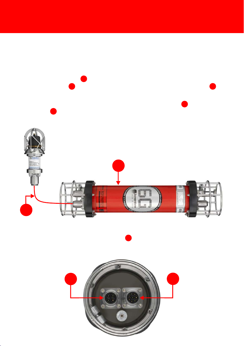
23451Transportation case2ROVNav 63Remote Transducer45 metres TCVR Power/Comms Cable (312-8017)54 metre Remote Transducer Link Cable (318044)6G Instrument Test Box (620-0187) - not shownDummy Plug (312-6005) - not shownCD-ROMS (920-0000 and 920-2000)2-Drivers are required to enable operation of the Test Box. These are supplied on the 6G Utilities CD (920-2000) and require installation onto the PC before the Test Box is connected to the ROVNav 6. For any further information please refer to the ROVNav 6 User Manual (UM-8310), Section 9.1On receipt of the equipment, visually inspect for any signs of damage, e.g. corrosion, dents, bent electrical pins etc.2Make sure all Warning and Caution labels on the equipment are read and understood. Refer to the equipment manual for further information and assistance.
PRE-INSTALLATION CHECKSSTEP 3
1
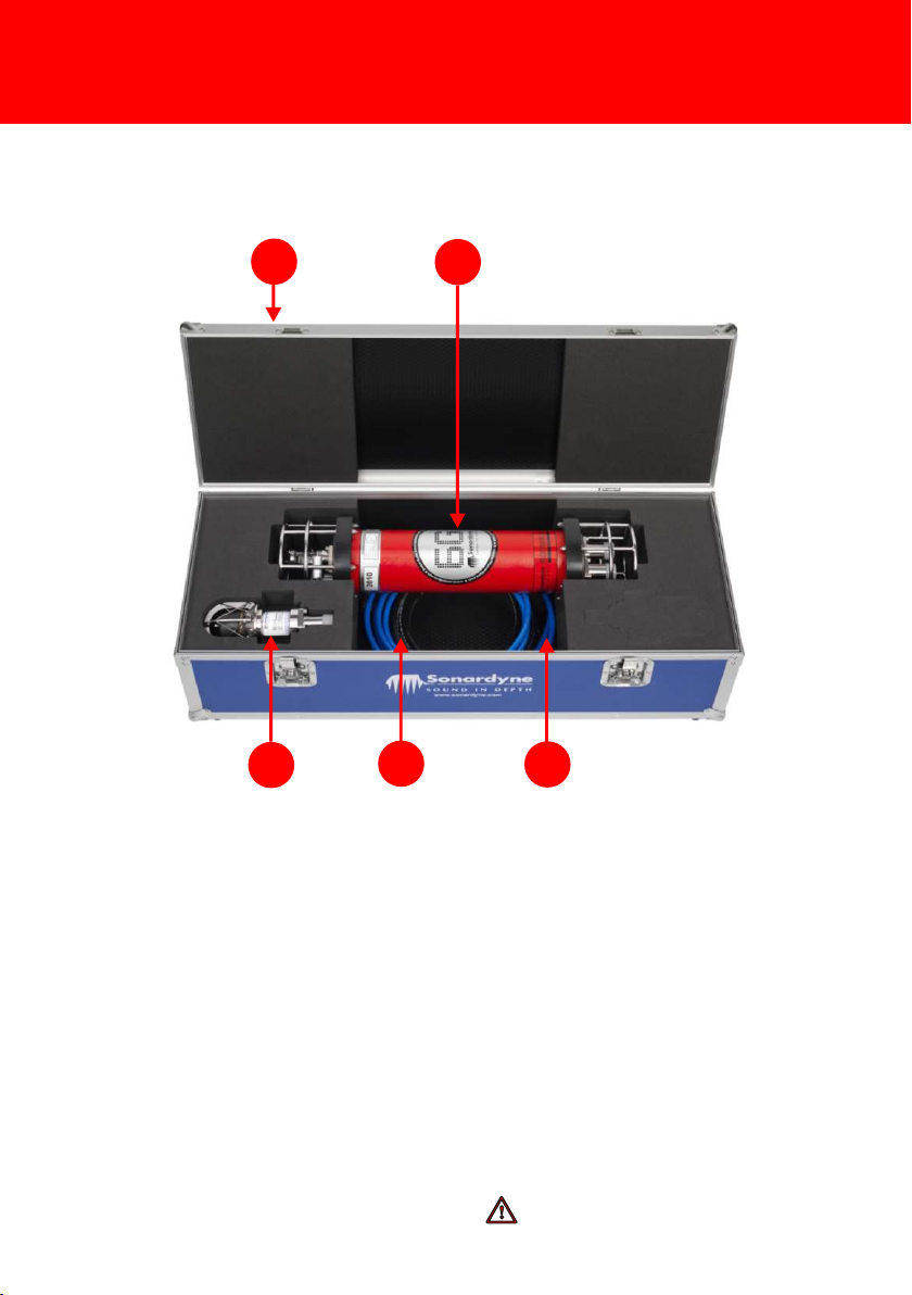
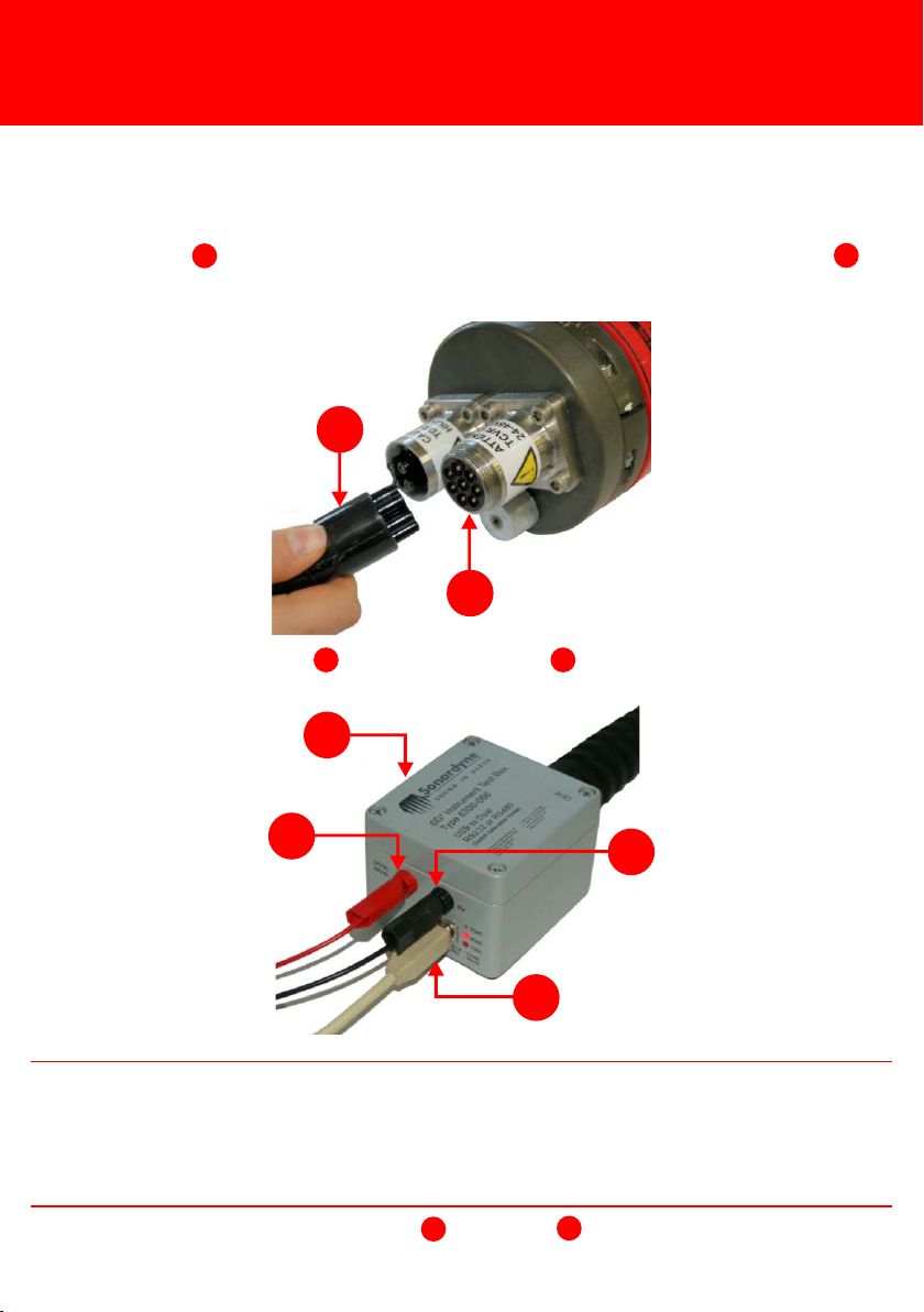
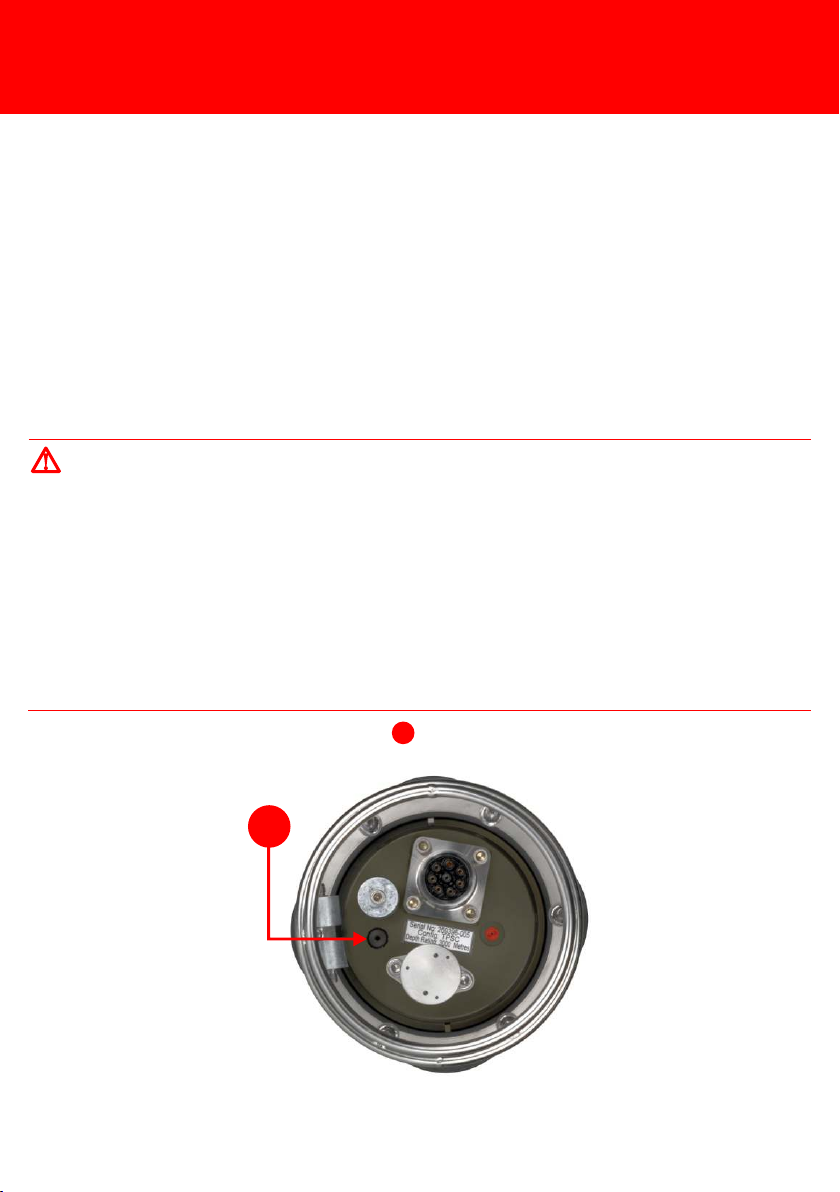
Before installation, it is recommended the ROVNav 6 is checked for operation.1Check the Pressure Relief Vent Valve is flush with the end-cap. If the valve is found to be protruding refer to the ROVNav 6 User Manual UM-8310 for instructions on releasing the internal pressure.1Electric shock hazard risk if the Remote Transducer output connector contacts are touched whilst the transducer cable is disconnected, the unit is powered and if instructed to transmit. Never touch the connector contacts whilst the power is on. WARNING2Remove the protective cover from the Remote Transducer 4-Way AGP connection .3Using the Remote Transducer 4-Way AGP cable (312-8044) connect the Remote Transducer to the Remote Transducer 4-Way AGP connection on the ROVNav 6.23323
STEP 4
1
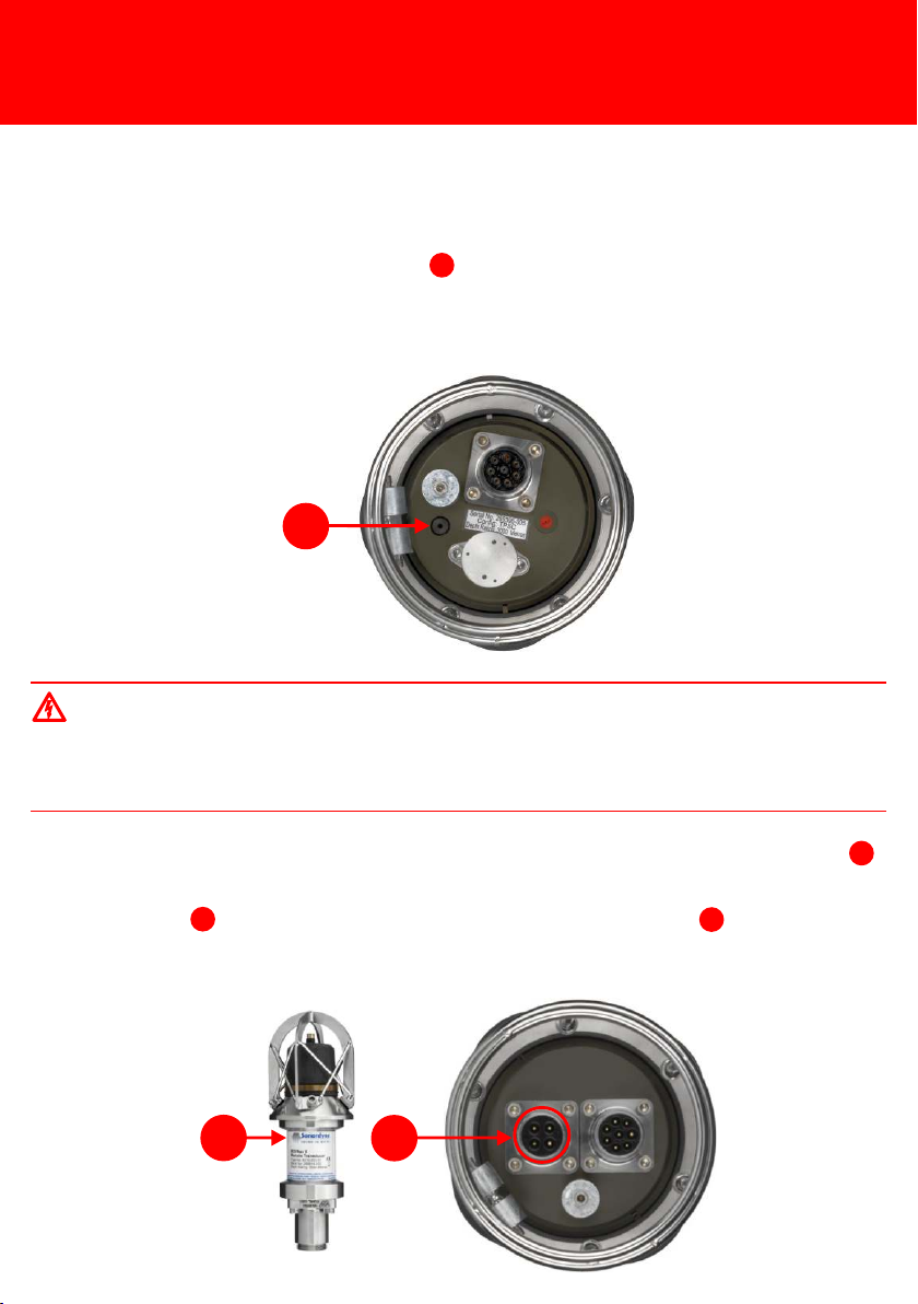
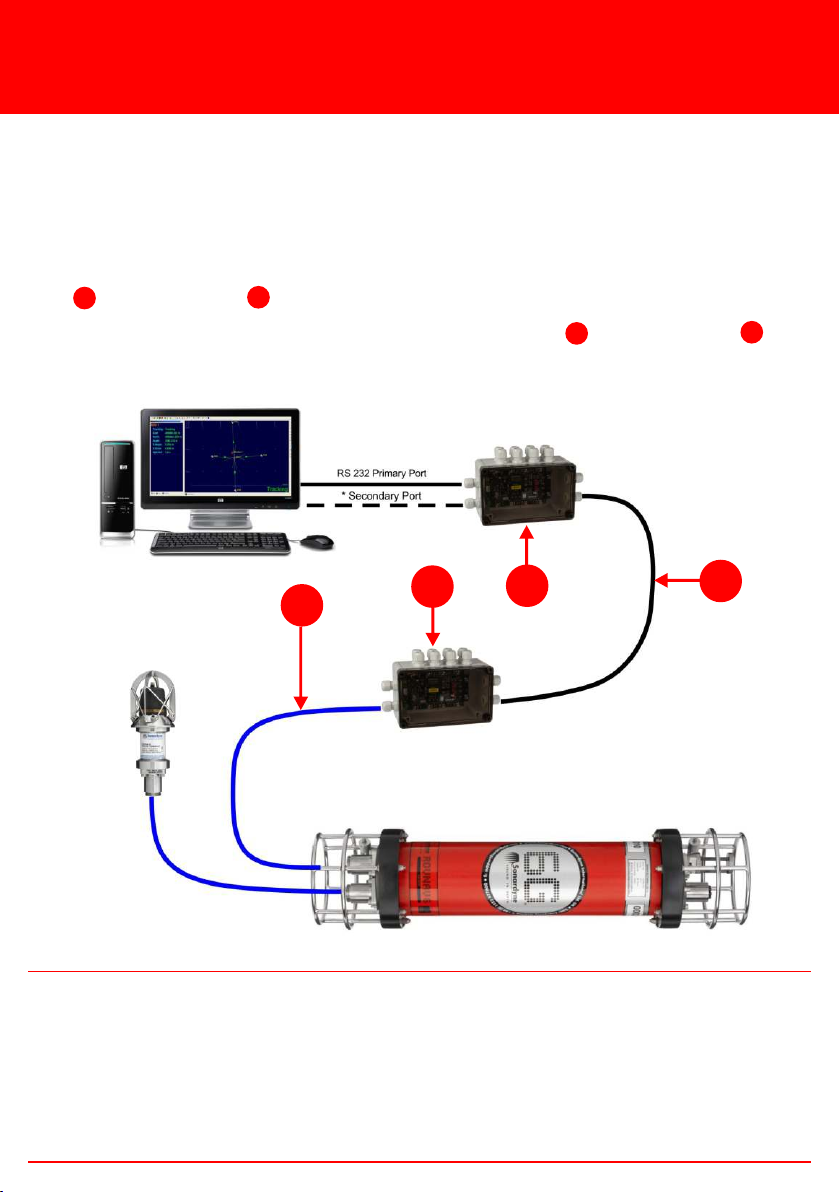
24Remove the protective cover from the TCVR Comms & Power 8-Way AGP Male connection on the Remote End-cap and connect the 6G Instrument Test Box (Type 8300-066).12As soon as the Test Box is connected to the PC, the two mode lights will illuminate: Red for RS232, Blue for RS485. If the mode lights are not illuminated when the PC is connected, refer to the ROVNav 6 manual UM-8310 for instructions on how to change the Test Box mode.2NOTE345
6
5Using a USB connection , connect the Test Box to a PC.356Connect a power supply to the red and black connections on the Test Box. This will supply power to the ROVNav 6 and automatically connect the battery.46PRE-INSTALLATION CHECKS

Carry out the acoustic check before installing the ROVNav 6 onto an ROV.1Open the 6G Terminal Lite software by doubling clicking on the desktop icon.2Click Connect.3In the Select Port window select the correct port the PC is connected to and the Baud Rate from the drop down menu. Click Connect.4In the Range Test section of the 6G Setup tab click Set.5An Address Selector window will appear listing all available addresses for Wideband 2. Select the address for the attached device then click OK.STEP 5ACOUSTIC CHECK USING 6G TERMINAL LITEPRE-INSTALLATION CHECKSA Comms Log window will open when the ROVNav 6 is connected to the 6G Terminal Lite software. The green writing is the commands sent from the software to the transceiver, the blue writing is the response from the transceiver. Do not close this window as it can be used for diagnostic purposes.2NOTE
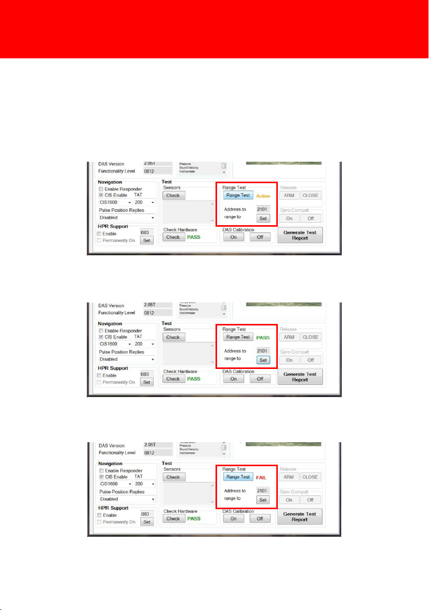
6The 6G Setup tab will appear with the selected address in the Range Test Address to window. Click Range Test to begin the acoustic check.STEP 67If the Acoustic Check is successful Pass will appear next to the Range Test button.8If the Range Test is unsuccessful Fail will appear next to the Range Test button.PRE-INSTALLATION CHECKSACOUSTIC CHECK USING 6G TERMINAL LITE9If Fail appears it is recommended the transceiver and attached device are moved and then the Range Test repeated. If the Range Test continues to fail contact the Sonardyne Support Team for assistance.
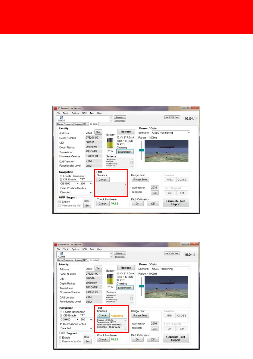
STEP 7SENSOR CHECK USING 6G TERMINAL LITE SOFTWARETo carry out a check of the ROVNav 6 sensors proceed as follows:1In the 6G Setup tab, click Check to perform a test of all sensors installed in the transceiver.2Acquiring will appear to indicate all sensor information is being gathered.PRE-INSTALLATION CHECKS

STEP 83If all information has been gathered successfully Pass will appear.4On completion of all tests to electrically disconnect the battery click Disconnect on the 6G Setup tab.PRE-INSTALLATION CHECKSSENSOR CHECK USING 6G TERMINAL LITE SOFTWAREThe inclination values refer to the roll then pitch in degrees.2NOTE
STEP 9INSTALLING THE ROVNAV 6 AND REMOTE TRANSDUCER ONTO AN ROVMake sure the ROVNav 6 is acoustically and electrically isolated from the ROV body.The Remote Transducer Cable (312-8044) is limited to 4 metres in length. Position the Remote Transducer so it is no more than 4 metres and has a clear line-of-sight view of the target transponder.Make sure the battery is connected prior to using the ROVNav 6 for acoustic commands, this reduces the power requirements from the ROV MUX.INSTALLING THE EQUIPMENTDo not attach the Remote Transducer to an extendable ram on an ROV if the extended ram and location of the ROVNav 6 is over 4 metres.When securing the Remote Transducer to an extendable ram, make sure the cable does not become trapped when the ram is retracted.Do not allow cables to vibrate on the outside of the hull where flow may make the cable strum and fatigue.The TCVR Comms & Power 8-Way Cable (312-8017), and Remote Transducer Cable (312-8044) are flexible, but the bend radius should not be too tight. Do not kink the cables. WARNINGS
1
1Check the Pressure Relief Vent Valve is flush with the Sensor End-Cap Assembly.12If the Remote Transducer is being attached to a ram on the ROV, make sure the ram is fully extended.

STEP 10INSTALLING THE ROVNAV 6 AND REMOTE TRANSDUCER ONTO AN ROV3Locate the Remote Transducer 4-Way AGP Cable (312-8044) onto the ROV, and secure in place. Make sure the cable will not become trapped when the ram is retracted.4Position the Remote Transducer onto the ROV and secure in place.5Connect the Remote Transducer 4-Way AGP Cable (312-8044) to the Remote Transducer .11
1
26Make sure the dummy plug is fitted securely to the 8-Way AGP Male connection on the Sensor End-Cap Assembly.2INSTALLING THE EQUIPMENT
STEP 11INSTALLING THE ROVNAV 6 AND REMOTE TRANSDUCER ONTO AN ROV9Connect the TCVR Comms & Power 8-Way AGP Cable (312-8017) to the TCVR Comms & Power 8-Way AGP connection on the Remote Transducer End-Cap Assembly.42
1
3437Position the ROVNav 6 onto the ROV so the Remote Transducer 4-Way AGP Cable (312-8044) can easily be connected to it. Secure the ROVNav 6 in place.8Connect the Remote Transducer 4-Way AGP Cable (312-8044) to the ROVNav 6 . 2112INSTALLING THE EQUIPMENT
STEP 12It should be noted the ROVNav 6 does not require a Sonardyne Navigation Sensor Hub (NSH) or Surface Interface Unit (SIU) as it will often be powered by the ROV and serial communications will be multiplexed through the ROV umbilical. It is optional to connect the secondary port through the MUX; this is only normally used for modem data received from Sonardyne logging transponders, such as AMTS.2NOTE
1
23410Connect the other end of the TCVR Comms & Power 8-Way AGP Cable (312-8017) to the ROV Mux . 11Connect the other end of the ROV umbilical connections to the ROV Mux in the control room.1234INSTALLING THE ROVNAV 6 AND REMOTE TRANSDUCER ONTO AN ROVINSTALLING THE EQUIPMENT

STEP 14RETRIEVAL & STORAGEWhen the ROVNav 6 is not being used, it should be placed in storage to make sure it remains fully operational.Electric shock hazard risk if the Remote Transducer output connector contacts are touched whilst the transducer cable is disconnected, the unit is powered and if instructed to transmit. Never touch the connector contacts whilst the power is on. WARNING6Disconnect all electrical connections.7Check the Pressure Relief Vent Valve is flush with the Sensor End-Cap.8Release the ROVNav 6 from its secure location on the ROV.9Release the Remote Transducer from its secure location on the ROV.10Remove the connecting cables.11Pack all components into the transportation container and store in a dry secure area.1Rinse the ROVNav 6, Remote Transducer and connecting cables with clean fresh water.2Dry the ROVNav 6, Remote Transducer and connecting cables with a clean lint free cloth.3For extended periods of storage it is recommended the battery is electronically disconnected.4Connect to the 6G Terminal Lite software as detailed in Step 5.5In the 6G Setup tab navigate to the Battery section. Click Disconnect to electrically disconnect the battery.The ROVNav 6 weighs 13 kg, Manual Handling Equipment (MHE) must be used to move the transceiver. If MHE is not available, then a manual handling assessment must be carried out prior to carrying out manual lifting / handling. Make sure Personal Protective Equipment such as protective footwear and gloves are worn before lifting this equipment. WARNINGBattery reconnection will require an external power supply to initially power the unit.For further information on the ROVNav 6 go to: http://www.sonardyne.com/products/all-products/instruments/730-rovnav-6.html.2NOTE

Global Headquarters, UKT. +44 (0) 1252 872288F. +44 (0) 1252 876100[email protected]Houston, USAT. +1 281 890 2120F. +1 281 890 7047[email protected]24/7 Emergency Hotline+44 (0) 1252 877600Email Support[email protected]Websitewww.sonardyne.comTwitter@sonardyneAberdeen, UKT. +44 (0) 1224 707875F. +44 (0) 1224 707876[email protected]Rio das Ostras, BrazilT. +55 22 2123 4950F. +55 22 2123 4951[email protected]Singapore, AsiaT. +65 6542 1911F. +65 6542 6937[email protected]QSG-IG-8310-A108/2013910-0003ACOUSTIC POSITIONINGINERTIAL NAVIGATIONllWIRELESS COMMUNICATIONlSONAR IMAGING
Other manuals for 6G ROVNAV 6
1
Table of contents
Other Sonardyne Transceiver manuals


