manuals.online logo
Brands
  1. Home
  2. •
  3. Brands
  4. •
  5. Sonelco
  6. •
  7. Power Supply
  8. •
  9. Sonelco P3262 User manual

Sonelco P3262 User manual

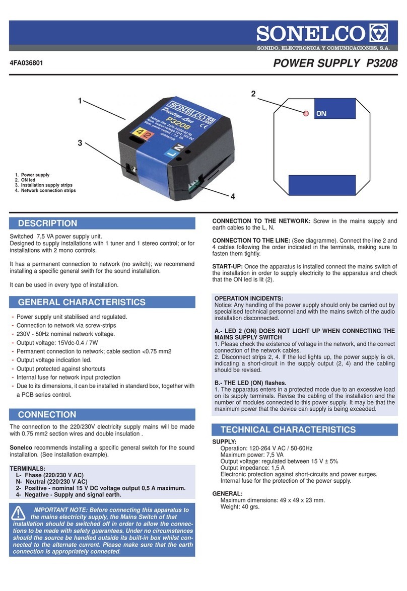
POWER SUPPLY UNIT P3262 - P3263
MODELS: P3262 (230Vac) P3263 (115Vac)
DESCRIPTION
Switched 60 VA power supply unit to install on DIN rail, designed
to make installation more flexible if used in combination with the
PC3110 input modules and with the PC3810 telecontrol module
for external audio source.
It can be used in any system:
To supply the system in combination with one or several
PC3110 audio input modules.
For systems that only use the SONELCO Prestige series
tuners as sound sources.
As a power supply unit for any type of Prestige Line system
GENERAL CHARACTERISTICS
Power supply unit to install on DIN rail
Mains connection by screwed strips.
Rated mains voltage 230V (Optional 115V on order)
50/60Hz.
Permanent connection to mains (no switch)
Output voltage indicator LED.
60W maximum power
Stabilised and regulated 16V output voltage
Output protected against short circuits
Internal mains input protection fuse
EC marking (UNE-EN60065 and CEM)
-
-
-
-
-
-
-
-
-
-
-
-
-
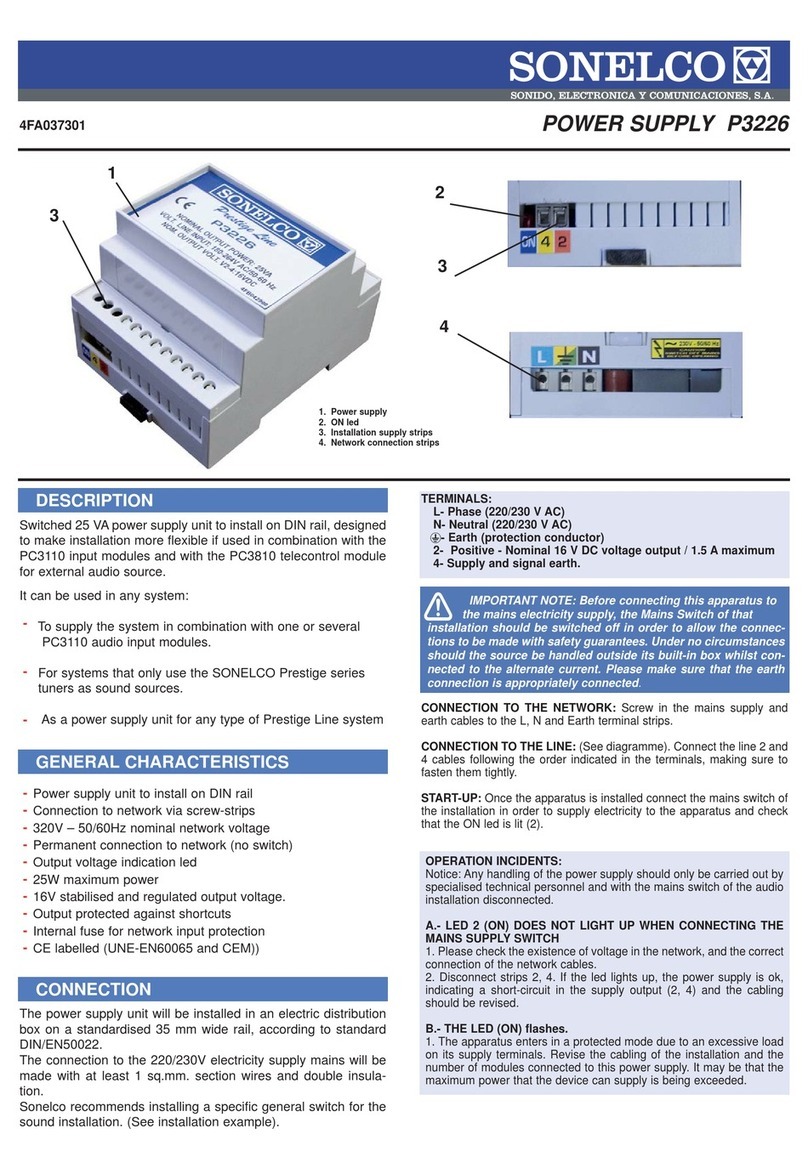
CONNECTION
1 – Power supply unit
2 – Ignition LED
3 – Installation supply strips
4 – Mains connecting strips
TERMINALS:
F- Phase (220/230 V AC)
N- Neutral (220/230 V AC)
Earth (protection conductor)
2- Positive – 16 rated V DC / 4 A maximum voltage output
4- Negative – Signal and supply ground
CONNECTION TO MAINS: screw the power and earth cables to the N,
F and Earth strips.
CONNECTION TO LINE: (See diagram). Connect cables of lines 2 and
4 following the order indicated for the terminals, making sure they are
tightly connected.
Start-up:
Once the unit has been installed, connect the general switch of the
system to provide the unit with power and verify that the ON LED (2)
comes on..
OPERATION INCIDENTS
Warning: Any operations to the unit must only be carried out by
specialised technical personnel and with the general switch of the
audio system disconnected.
A – LED 2 (ON) DOES NOT COME ON WHEN THE ON/OFF SWITCH
IS ACTIVATED
1- Verify the existence of mains voltage, and the correct connec-
tion of the power cables.
2- Disconnect strip 2,4. If the LED comes on, the unit is correct,
indicating a short circuit in the supply output (2,4). The wiring
must be reviewed.
B- THE (ON) LED FLASHES ON AND OFF.
1- The unit enters protected mode due to excess load in its supply
terminals. Review the system wiring and the number of modules
connected to this unit. The maximum power that the unit can
supply may have been exceeded.
The power supply unit will be installed in an electric distribution box on a
standardised 35 mm wide rail, according to standard DIN/EN50022.
The connection to the 220/230V electricity supply mains will be made
with at least 1 sq.mm. section wires and double insulation.
Sonelco recommends installing a specific general switch for the sound
installation. (See installation example).
4FA020001
1
2
4
3
IMPORTANT NOTE: Before connecting this unit to the
electricity supply mains the general switch of that system
must be disconnected in order to make the connection with
due safety guarantees. Under no circumstances must the unit
be manipulated outside its flushmount box if connected to the
alternating current network. Make sure that the Unit has been
correctly connected to earth..
These characteristics are only given as reference. The manufacturer reserves the right to introduce any amendments without prior notice in order to improve the product. P3262/63 -16-06-06
TECHNICAL CHARACTERISTICS
INSTALLATION EXAMPLES
SUPPLY:
Operation: 180-264 V AC / 50-60Hz for P3262
92-132 V AC / 60-60 Hz for P3263
Maximum power: 60 VA
Voutput: regulated between 16 V ± 5%
Ioutput: 4 A max.
Electronic protection against short circuits and overloads in the output.
Internal protection fuse of the power supply unit
GENERAL:
Maximum dimensions: 155 x 85 x 58 mm.
Weight: 350 grams.
In the Sonelco General Diagrams, you will find connection diagrams and recommended cable sections for the audio installation. Do not place this product
in damp places, close to heat sources or in potentially explosive atmospheres.
The connection to the electricity mains supply, installation, cable section, and wire laying will be done according to the specific directives and standards
of each country.
Sonelco recommends installing a specific general switch for the sound system. (See installation example).
Sonelco declines any responsibility that might be derived from the improper use of the product or installation that does not comply with the recommen-
dations.
FIG. 1 – CENTRALISED INSTALLATION WITH 4 STEREO CHANNELS
FIG. 2 – CENTRALISED INSTALLATION WITH 2 STEREO
CHANNELS (ONE EXTERNAL CHANNEL + TUNER PC3666)
WITH TELECONTROL MODULE PC3810
FIG. 4 – CENTRALISED INSTALLATION WITH 2 STEREO CHANNELS
(ONE EXTERNAL CHANNEL
+ TUNER PC3666)
WITH DOMOTIC CONTROLS
PCD1307
FIG. 3 – CENTRALISED INSTALLATION WITH 1 STEREO CHANNEL
CONNECTION OF LOCAL TUNER/CONTROL PC1271
CONNECTION OF DOMOTIC BUS
It replaces the control cables used in
other installations, for general inter-
com and by zones, messages, survei-
llance and remote scan.
It also transmits the frequencies of
each station from the tuner to the
domotic controls PCD1307.
INSTALLATION RECOMMENDATIONS
Por GERARDO fecha 9:02 , 16/06/2006

This manual suits for next models

1

Other Sonelco Power Supply manuals

Sonelco P3208 User manual

Sonelco

Sonelco P3208 User manual

Sonelco P3270 User manual

Sonelco

Sonelco P3270 User manual

Sonelco P3226 User manual

Sonelco

Sonelco P3226 User manual

Popular Power Supply manuals by other brands

Bentel Security BAQ15T12 quick start guide

Bentel Security

Bentel Security BAQ15T12 quick start guide

SOMFY Sonesse 30 RS485 Integration guide

SOMFY

SOMFY Sonesse 30 RS485 Integration guide

Emerson SmartPower 701PBK quick start guide

Emerson

Emerson SmartPower 701PBK quick start guide

Vimar Eikon quick start guide

Vimar

Vimar Eikon quick start guide

TDK-Lambda ELC50 Series instruction manual

TDK-Lambda

TDK-Lambda ELC50 Series instruction manual

Altronix LPS3C12X220 quick start guide

Altronix

Altronix LPS3C12X220 quick start guide

ANSMANN AP 312 operating instructions

ANSMANN

ANSMANN AP 312 operating instructions

KORAD KWR Series user manual

KORAD

KORAD KWR Series user manual

PCB Piezotronics F482A20 Installation and operating manual

PCB Piezotronics

PCB Piezotronics F482A20 Installation and operating manual

Kurt J. Lesker R Series Operator's manual

Kurt J. Lesker

Kurt J. Lesker R Series Operator's manual

Hioki 3272 instruction manual

Hioki

Hioki 3272 instruction manual

Allanson 2270 Series instruction manual

Allanson

Allanson 2270 Series instruction manual

Pyle PSL142X instruction manual

Pyle

Pyle PSL142X instruction manual

Synthesis Technology MOTM-900 Assembly instructions & owner's manual

Synthesis Technology

Synthesis Technology MOTM-900 Assembly instructions & owner's manual

TDK-Lambda Genesys GEN8-300 user manual

TDK-Lambda

TDK-Lambda Genesys GEN8-300 user manual

Xantrex XPower Powerpack 300 Plus owner's guide

Xantrex

Xantrex XPower Powerpack 300 Plus owner's guide

DuraComm LPB-24 Product user guide

DuraComm

DuraComm LPB-24 Product user guide

ABB 4234 600 instruction manual

ABB

ABB 4234 600 instruction manual

manuals.online logo
manuals.online logoBrands
  • About & Mission
  • Contact us
  • Privacy Policy
  • Terms and Conditions

Copyright 2025 Manuals.Online. All Rights Reserved.