Sonelco P3270 User manual

POWER SUPPLY UNIT P3270-73
DESCRIPTION
In large systems, as an auxiliary power supply unit, to supply part of
the system, combined with a sound unit.
As a power supply unit for a public address system.
For systems which only use the SONELCO Prestige series tuners as
sound units.
Theunitcanbeswitchedonmanuallyorautomatically.Manuallywhen
it is switched on with the Power (mains) switch (3). Automatically,
when it comes on automatically when the sound unit is switched on.
GENERAL CHARACTERISTICS
CONNECTION
1 - Operation indicator Led
2 - Remote connection indicator Led
3 - Power (mains) switch
4 - Mains connection strip
5 - Connection strips to sound system
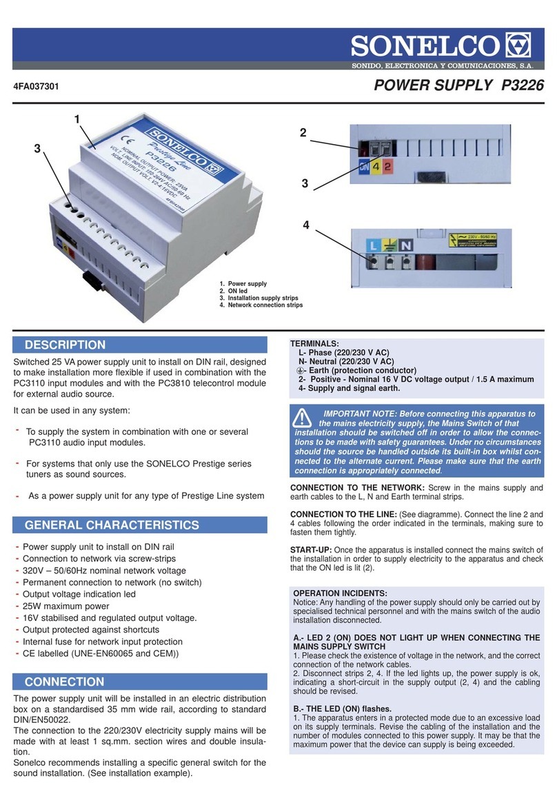
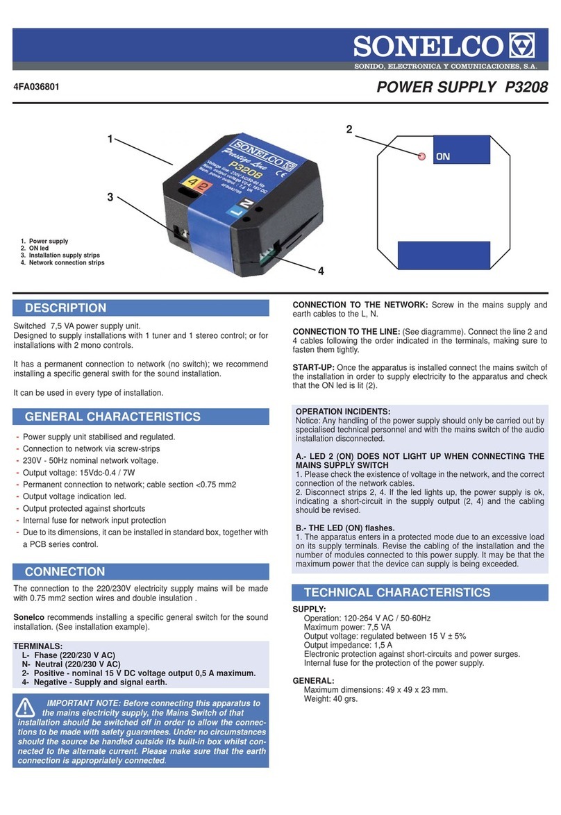
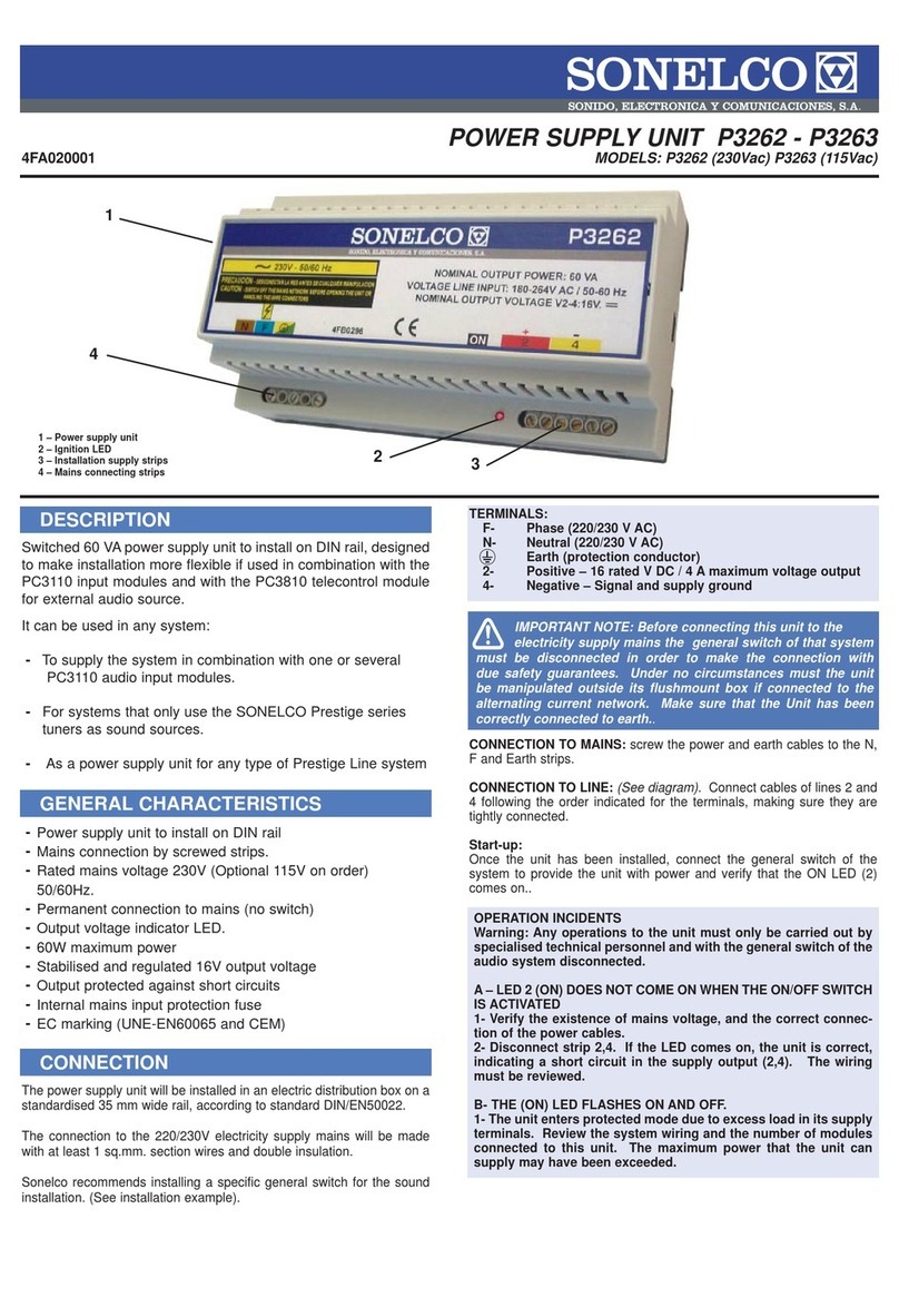
TERMINALS:
F- Fhase (P3270 - 220/230 V AC) (P3273 - 115/125 V AC)
N- Neutral (P3270 - 220/230 V AC) (P3273 - 115/125 V AC)
Earth (protection conductor)
2- Positive - voltage output 16 V DC nominal/4.5 A maximum
4- Negative - Signal and supply ground
1- Auxiliary terminal for remote connection of the supply unit.
(connect to terminal 2 of the sound unit)
CONNECTION TO MAINS: Insert the mains an the earth wires, through
the holes situated on the metal plate into the terminal strip (4) (to the right
of the mains switch) Tigten the screws of the strip and make sure that no
wire thread is outside the holes.
CONNECTION TO THE LINE: (See diagram). Connect the wires of the
sound line to the strip (5), following the order indicated for the terminals.
Make sure the screws are tightened correctly.
For remote ignition (terminal 1 must be connected)
Terminal 1 permits the remote ignition of the unit. It is used if the supply
unit is connected as an auxiliary one to the sound unit.
To achieve this we will leave switch (3) on OFF, and we will connect ter-
minal 1 of the supply unit to terminal 2 of the main unit. When switching
the sound unit on the power supply unit will come on automatically, and
green led (1) and (2) on the front will light up.
For “Local” ignition (terminal 1 not connected)
Just put the ON/OFF (3) switch on ON.
Starting:
Once the main unit has been installed in its casing (flush-mount or sur-
face box), screw the base plate to the box and fit the trim frame (with
the coloured strips if desired). Then connect the power switch to supply
electricity to the main unit.
On local ignition mode: (Terminal 1 not connected, or sound unit off).
Operate the power switch (3) and check the ON led (1) comes on. The
green led must go out.
Remote ignition mode: (Terminal 1 connected to 2 of the main unit, ON/
OFF switch in OFF position). Switch on the sound unit and check that
the ON led (2) and the GREEN led are on, indicating remote ignition.
Regulated output voltage, supplying 16 V DC
Mains input voltage: P3270 230V AC - P3273 115V AC
Electronic protection against short-circuits and overloads in the
supply.
Two-pin power switch (3) to switch the unit on.
Power supply unit operation indicator Led (1).
Remote connection indicator Led (2), automatic operation.
Mains input protection fuse (4).
All the components used for connection to the mains are officially
approved, complying with the strictest safety regulations.
CE Mark (UNE-EN60065 and EMC)
The supply unit will be installed in a P9002 flush box or P9026 surface
box, preferably near to the sound supply unit.
The connection to the mains will be done with at least 1 sq.mm. section
wires and double insulation.
NOTE: It is advisable for the cables of the electricity supply mains to be
as far away as possible from the circuit of the main unit.
-
-
-
-
-
-
-
-
-
-
-
-
-
4FA021401
P3270 (230Vac)
P3273 (115Vac)
60 VA Commutated power supply unit
It can be used:
IMPORTANT NOTE: Before connecting this unit to the
electricity supply mains the power switch of that system must
be disconnected to make sure the connection is made with the correct
safety guarantees. Under no circumstances must the unit be handled
outside its flush box whilst connected to the alternating current network.
Make sure the unit has been correctly connected to earth.

These characteristics are only given as reference. The manufacturer reserves the right to introduce any amendments without prior notice in order to improve the product. P3270-73 / 15-06-06
TECHNICAL CHARACTERISTICS
INSTALLATION EXAMPLE INSTALLATION RECOMMENDATIONS
SUPPLY:
Operation: 180-264 V AC / 50-60Hz for P3270
92-132 VAC / 50-60Hz for P3273
Maximum power: 60 VA
Voutput: adjusted between 16V ± 5%
Ioutput:: 4 A max.
Electronic protection against short-circuits and overload in the
output.
Internal protection fuse of the power supply unit.
REMOTE IGNITION:
MinimumV in terminal 1: 9 V
LED indicator (green) of activation of remote control.
GENERAL:
Maximum dimensions: : 142 x 146 x 50 mm.
Minimum flush space: 120 x 120 x 40 mm.
Weight: 420 grs.
KM9211-01 (WHITE) KM9211-02 (CHARCOAL) KM9211-03 (TWO-TONE)
In Sonelco’s General Diagrams, you will find connection diagrams and cable sections recommended for the audio installation.
Do not install this product in damp places, near heat sources or in potentially explosive atmospheres.
The connection to the mains, installation, cable section and wiring will be done in accordance with the directives and specific regulations of each coun-
try.
Sonelco recommends installing a specific on/off switch for the sound system (See installation example).
Sonelco declines any responsibility which might be derived from the incorrect use of the product or installation not in accordance with that
DOUBLE FRONT FRAME + SUPPLEMENT FOR "SONELCO" BOXES:
During the installation of main units and power supply units, it is advisa-
ble to fit the supplement (3). By doing this an extra 12 mm. bottom is
achieved on the flushmount box (1), which makes assembly easier and
provides greater ventilation.
To correctly assemble the supplement:
-Remove the four screws (5) from the flushmount box (1)
-Pass the wires through the supplement (3)
-Connect and screw the module (4) together with the supplement (3) to
the flushmount box (1)
-Place the frame (2) on the base plate (4) and press
-Place the side screws (7)
-Put the covers (8) on the sides (2)
-Optionally, trims can be fitted (6)
OPERATION INCIDENTS:
Warning: The power supply unit must only be handled by specialised
technical personnel and with the power switch of the audio system
disconnected.
A.- IF LED 9 (ON) DOES NOT LIGHT UP WHEN THE POWER
SWITCH IS ACTIVATED
1 - Check that there is voltage, that the mains wires are correctly con-
nected or if fuse (4), (situated under the upper lid) has blown. If this
fuse has blown replace it with another one of the same characteristics
and value.
2 - Disconnect strip 2, 4. If the led comes on, the power supply unit is
OK, indicating a short circuit in the supply output (2,4) having to check
the wiring.
B.- THE (ON) LED BLINKS ON AND OFF.
1 - The main unit is on protected mode due to excess load in its supply
terminals. Inspect the wiring of the system and the no. of modules con-
nected to this power supply unit. The maximum power that the unit can
supply may have been exceeded.
AS A CENTRALISED
INSTALLATION
AS AN AUXILIARY
POWER SUPPLY
GENERAL LINE
Max.
4000MA
in total
Max.
4500MA
in total
Main unit
ON/OFF SWITCH
INSTALLATION RECOMMENDATIONS
Por GERARDO fecha 10:02 , 15/06/2006
This manual suits for next models
1
Other Sonelco Power Supply manuals
Popular Power Supply manuals by other brands

Videx
Videx 520MR Installation instruction

Poppstar
Poppstar 1008821 Instructions for use

TDK-Lambda
TDK-Lambda LZS-A1000-3 Installation, operation and maintenance manual

TDK-Lambda
TDK-Lambda 500A instruction manual

Calira
Calira EVS 17/07-DS/IU operating instructions

Monacor
Monacor PS-12CCD instruction manual


