SONNEMAN purolinear 360 User manual

purolinear 360™
assembly instructions

July 7, 2020
©2020 SONNEMAN - A Way of Light
1 of 7
Purolinear 360™ Product Information and Warnings
Important
• Always disconnect the power before installing or replacing Luminaires and before cleaning or
other maintenance.
• Consult a qualied, licensed electrician to ensure correct branch circuit conductor.
Consulter un électricien qualié pour vous assurer que les conducteurs de la dérivation sont adéquats.
• THIS PRODUCT MUST BE INSTALLED IN ACCORDANCE WITH THE APPLICABLE INSTALLATION CODE BY A PERSON
FAMILIAR WITH THE CONSTRUCTION AND OPERATION OF THE PRODUCT AND THE HAZARDS INVOLVED.
CE PRODUIT DOIT ÊTRE INSTALLÉ CONFORMÉMENT AUX DISPOSITIONS APPLICABLES CODE D'INSTALLATION PAR UNE
PERSONNE FAMILIÈRE AVEC LA CONSTRUCTION ET LE FONCTIONNEMENT DU PRODUIT ET LES RISQUES.
• Suitable for Damp Locations. Convient aux Emplacements Humides.
• Please read all included assembly instructions and warnings carefully before installation. Contact Customer
Service if you have any questions or concerns. Before installation, please conrm that the xture is compatible
with your supply voltage and dimming system, if present.
• LEDs are highly sensitive electronic devices, and must be treated with care. Do not open any factory sealed
compartments, and avoid touching the LEDs with your hands or any object.
• Although all our xtures are equipped with protective devices, LED electronic systems are vulnerable to power
surges and supply variations. Do not install LED xtures on the same circuit as any motors, appliances, or HVAC
systems.
• Any mounting hardware is provided for your convenience and should be used with discretion. Always use the
appropriate hardware for the mounting surface.

24", 36", 48"
23CxxL111
Small Linear Connector
with 4 ½" Canopy
23CxxE111
Small End Connector
with 4 ½" Canopy
July 7, 2020
©2020 SONNEMAN - A Way of Light
2 of 7
Connectors
Welcome to Purolinear 360™
A Purolinear 360 conguration is built from LED Luminaires and Connectors. Illumination radiates from the Luminaires, which
can be rotated in their Connectors to shine in any direction. The Connectors form a structural and electrical connection
between the Luminaires, and can be congured in many dierent ways. Any Connector can be used as a power feed.
23CxxX201
Large X Connector
23CxxT201
Large T Connector
23CxxC201
Large Corner Connector
Luminaires
23CxxL201
Large Linear Connector
23CxxL101
Small Linear Connector
23CxxE101
Small End Connector
23CxxE201
Large End Connector
23Lxx243090 - 24" Luminaire
23Lxx363090 - 36" Luminaire
23Lxx483090 - 48" Luminaire
2’
2’
2’
2’2’
2’
18’
PWR
FEED
2’
2’
2’
2’ 2’
2’
2’
2’
2’2’
2’
PWR
FEED
2’
2’
2’
2’ 2’
4’
2’
2’
2’
2’2’
4’
3’ 4’
4’
2’
3’
6’
7’
9’
8’
8’ 6’
2’
PWR
FEED
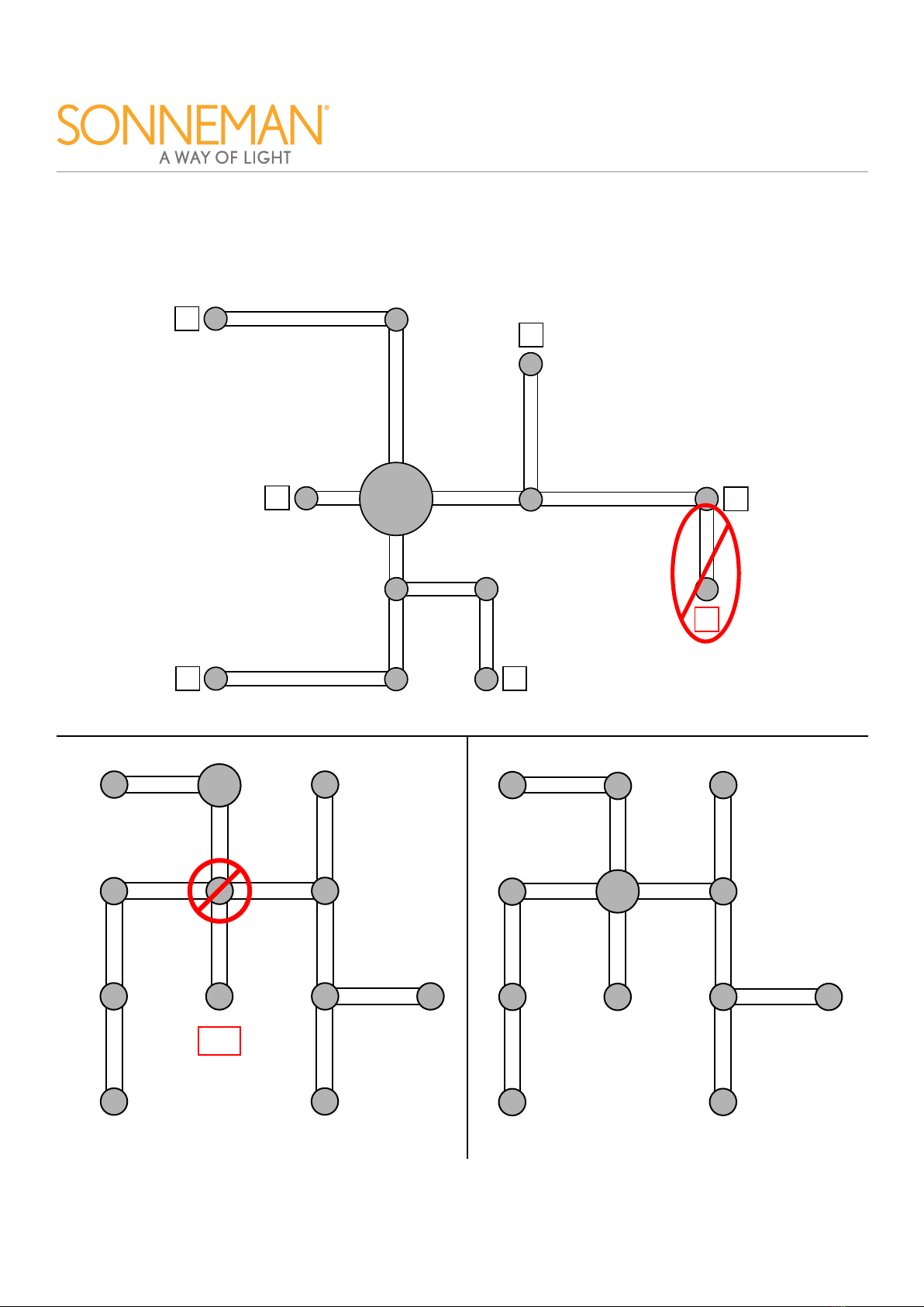
Fig. 1
Fig. 2
Fails #2
>16ft branching from X Connector
Passes #2
by relocating power feed
Fails #1
>8ft length from power feed
Fig. 3
July 7, 2020
©2020 SONNEMAN - A Way of Light
3 of 7
System Layout Considerations
To prevent electrical overload and avoid excessive voltage drop:
1. Do not exceed 8ft total Luminaire length from a power feed in any direction (Fig. 1).
2. Do not exceed 16ft total Luminaire length branching from a single Connector (except a power feed Connector) (Fig. 2-3).
3. Do not exceed 32ft total Luminaire length per power feed.
Place Sticker
Here
2’
4’
2’
2’ 2’
2’
3’ 4’
3’
PWR
FEED
PWR
FEED
2’
2’
4’
3’
4’ 4’
12’ Linear Unbalanced
4’ 8’
3’ 3’ 3’
6’ 6’
12’ Linear Balanced
PWR
FEED
PWR
FEED
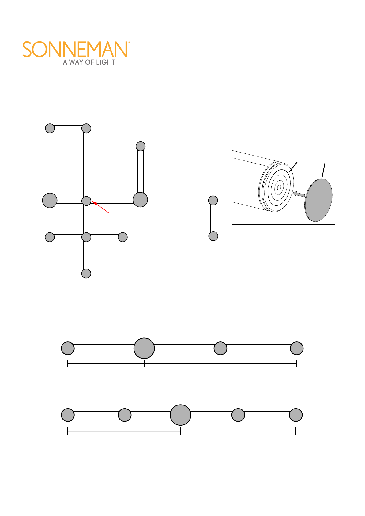
5. Balance the electrical load in a conguration by making the total Luminaire length in each branch as similar as possible. For
example, a 12ft linear conguration should be grouped in two 6ft sections, rather than a 4ft section and an 8ft section (Fig. 6).
6. Any Connector type may be used as a power feed.
Fig. 6
A
B
Fig. 5
4. Congurations that violate any of the prior requirements must be split into two or more electrically-isolated subsections,
each of which meets the requirements individually. Each subsection requires a separate power feed. See Fig. 4 for
an example conguration split into two subsections. Subsections are electrically isolated by applying the included
insulating stickers (A) to the Luminaire PCB (B) to block electrical contact between the appropriate Luminaires and
Connectors (Fig. 5).
Fig. 4
July 7, 2020
©2020 SONNEMAN - A Way of Light
4 of 7
System Layout Considerations (cont.)
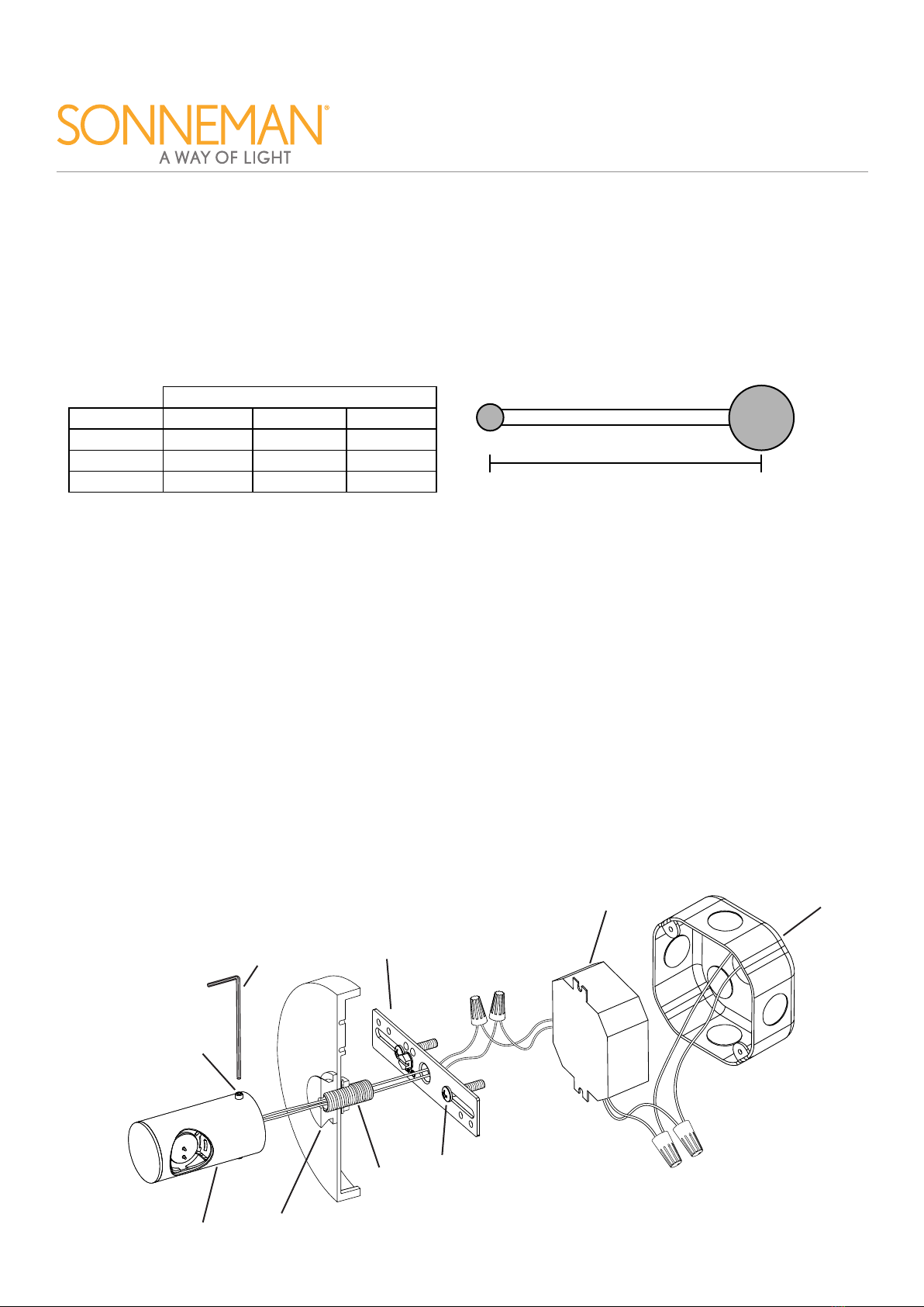
Mounting hole spacing
(center-to-center)
Connector Mounting Hole Spacing
2ft
3ft
4ft
24”
36”
48”
Luminaire Size Small-Small
Connector Sizes
24 ⁄”
36 ⁄”
48 ⁄”
Small-Large
24 ¾”
36 ¾”
48 ¾”
Large-Large
B
F
HD
G
C
E
A
Fig. 7
Table 1
J
July 7, 2020
©2020 SONNEMAN - A Way of Light
5 of 7
Connector Installation
Power Feed Connector with Outlet Box Driver - Shown with 23CxxE111 (Fig. 7)
1. Shut o power to the outlet box (A).
2. Make appropriate electrical connections using wire nuts:
a. Connect the LED driver’s (B) live wire to the live outlet box (A) wire.
b. Connect the LED driver’s neutral wire to the neutral outlet box wire.
c. Connect outlet box ground wire (green or uncoated) to the crossbar (C) using the green screw.
d. Pass Connector wires through center hole of crossbar.
e. Connect the LED driver's positive (+) output wire to the red connector wire.
f. Connect the LED driver's negative (-) output wire to the black connector wire.
g. Carefully place driver and connections in outlet box.
3. Install cross bar (C) to outlet box using outlet box screws (D).
4. Using included Allen key (J), loosen set screws (E) and remove Connector (F) from mounting bracket (G).
5. Secure canopy to mounting surface by screwing canopy nipple (H) into center hole of crossbar (C).
Note: Hold Connector (F) and keep wires slack. Do not allow wires to twist while screwing on canopy.
6. Place Connector (F) on mounting bracket (G) and secure by tightening set screws (E) using included Allen key.
System Installation
General steps for any conguration
1. Measure and mark the locations of all Connectors on the mounting surface. Refer to Table 1 for Connector spacing.
2. Install power feed Connector(s) in desired location(s) as shown on pages 5-6.
3. Install a neighboring Connector as shown on page 6.
4. Install Luminaire between Connectors as shown on page 7.
5. Repeat steps 3-4 for all remaining Connectors and Luminaires.
6. Restore power to the outlet box or branch circuit.

A
C
B
D
E
H
F
G
C
E
B
D
J
K
F
July 7, 2020
©2020 SONNEMAN - A Way of Light
6 of 7
Connector (non-Power Feed) - Shown with 23CxxE201 (Fig. 10)
1. Drill a ¾" hole where the Connector (B) is to be installed.
2. Loosen set screws (A) with included Allen key (F) and remove Connector (B) from mounting bracket (C).
3. Insert toggle anchor (D) through hole in wall and tighten screw (E) until it is secured in place.
4. Cap or trim exposed ends of Connector wires and place inside Connector (B).
5. Place connector (B) on mounting bracket (C) and secure by tightening set screws (A) with included Allen key.
Connector Installation (cont.)
Power Feed Connector with Remote Driver - Shown with 23CxxE201 (Fig. 8-9)
1. Shut o power to the branch circuit conductors.
2. The LED driver (A) must be installed in a remote and accessible location near the xture in accordance with local
electrical code (Fig. 9). Make appropriate electrical connections using wire nuts:
a. Connect the LED driver's (A) live wire to the live branch circuit conductor.
b. Connect the LED driver’s neutral wire to the neutral branch circuit conductor.
c. Connect the LED driver’s positive (+) output wire to the required length of red wire (not included) to reach the
Connector (B).
d. Connect the LED Driver's negative (-) output wire to the required length of black wire (not included) to reach the
Connector.
3. Drill a ¾" hole (J) in the wall where the Connector (B) is to be installed.
4. Using included Allen key (K), loosen set screws (H) and remove Connector (B) from mounting bracket (C).
5. Pull low voltage wires (F) through o-center hole (G) in mounting bracket (C).
6. Make appropriate electrical connections using wire nuts:
a. Connect the positive (red) low voltage wire to the Connector red wire.
b. Connect the negative (black) low voltage wire to the Connector black wire.
c. Carefully place connections inside Connector (C).
7. Insert toggle anchor (D) through hole in wall (J) and tighten screw (E) until it is secured in place, making sure not to
pinch the connector wires.
8. Place connector (B) on mounting bracket (C) and secure by tightening set screws (H) with included Allen key.
A
Fig. 9
Fig. 8
Fig. 10

B
A
A
A
D
Fig. 11
Fig. 12
C
Luminaire
Luminaire
Luminaire
C
July 7, 2020
©2020 SONNEMAN - A Way of Light
7 of 7
Luminaire Installation (Fig. 11-12)
1. Designate the two connectors on each side of the Luminaire as Aand B(Fig. 11). Leave Connector A fully installed to
mounting surface. Remove Connector B from its mounting bracket (C) by loosening set screws with included Allen key.
2. Angle the Luminaire into the ports on Connector A and B. Align Connector B with its mounting bracket.
3. Carefully pivot the Luminaire into both connector ports while moving Connector B onto its mounting bracket.
If necessary, adjust Connector B position to ensure Luminaire is fully inserted into both connector ports: loosen the toggle
anchor screw, adjust the bracket position, and retighten the toggle anchor screw.
4. Secure Connector B by tightening set screws with included Allen key.
Note: For some congurations, two Luminaires may need to be installed simultaneously to a shared Connector D (Fig. 12).
Follow steps 1-4 above with Connector D in place of Connector B.
Note: To remove Luminaire from Connector, gently tilt and pull Luminaire
to disengage Connector clips. Do not apply excessive force or damage to
the Luminaire and Connector may result.
Table of contents
Other SONNEMAN Lighting Equipment manuals


