Sono PV 2208 User manual

PV 2208 User Manual
1
PV 2208
User Manual
Copyright 2000 Publishing. All rights reserved.
This manual, software and firmware described in it are copyright by their respective
owners and protected under the laws of the Universal Copyright Convention. You may
not reproduce, transmit, transcribe, store in a retrieval system, or translate into any
language, in any form or by any means, electronic, mechanical, magnetic, optical,
chemical, biological, molecular, manual, or otherwise, any part of this publication
without the express written permission of the publisher.
All products and trade names described within are mentioned for identification
purpose only. No affiliation with or endorsement of the manufacturer is made or
implied. Product names and brands appearing in this manual are registered trademarks
of their respective companies.
The information published herein has been checked for accuracy as of publishing
time. No representation or warranties regarding the fitness of this document for any
use are made or implied by the publisher. We reserve the right to revise this document
or make changes in the specifications of the product described therein at any time
without notice and without obligation to notify any person of such revision or change.
Printed in Poland

PV 2208 User Manual
2
Item Checklist
Prior to beginning the installation of your mainboard, please insure that the following
materials have been provided:
?? One PV 2208 main board.
?? This user manual.
?? One Floppy disk drive cable.
?? One Ultra DMA/100 IDE cable.
?? One Software & Utility Pack CD.
If any of the above items are either damaged or missing, please contact your retailer.
PV 2208 Mainboard
Floppy Disk Drive Cable
Ultra DMA/100 IDE Cable
PV 2208 Manual
Software & Utility Pack CD

PV 2208 User Manual
3
Contents
1 Introduction
1-1Introduction 4
1-2Specifications 5
1-3Main Board Layout 7
2 Installation Procedures
2-1 Setting System Jumpers 9
2-2 System Memory (DIMM) 10
2-3 Central Processing Unit (CPU) 11
2-4 Expansion Cards 13
2-5 External Connectors 14
2-6 Power Connection Procedures 18
3 Award BIOS Setup
3-1 Introduction 19
3-2 Main Menu 22
3-3 Standard CMOS Setup 24
3-4 Advanced BIOS Features Setup 27
3-5 Chipset Features Setup 31
3-6 Power Management Setup 34
3-7 PNP/PCI Configuration 38
3-8 Defaults Menu 39
3-9 CPU Speed Setting 40
3-10 Integrated Peripherals 41
3-11 PC Health Status 43
3-12 Password Setting 44
3-13 IDE HDD Auto Detection 44
3-14 Exit Selecting 44

PV 2208 User Manual
4
Chapter 1 Introduction
1-1 Introduction
This mainboard contains the KT133 chipset from VIA Technologies
(www.via.com.tw). The VIA Apollo KT133 chipset unleashes the full performance
potential of AMD’s Duron and Athlon Thunderbird Socket A processors by providing
an extensive high-end feature-set that includes 200MHz FSB, AGP4X, PC133
memory and ATA-100.
The Best Choice for AMD Socket A Processors
The VIA Apollo KT133 is the first chipset available supporting the new AMD Duron
and Athlon Thunderbird Socket A processors. Building on the success of the VIA
Apollo KX 133 VIA’s first Athlon chipset, the VIA Apollo KT133 supports the same
high-end features:
Blistering AGP4X Graphics Performance
The VIA Apollo KT133 supports AGP4X, the latest high-performance
graphics bus technology, on the AMD Athlon processor platform. The
AGP4X interface enables the graphics controller to access the main memory
at double the speed of previous platforms, ensuring rich 3D graphics and
video performance on your AMD Athlon processor-based PC system.
High-Speed PC133 Memory
Through its advanced memory controller architecture, the VIA Apollo
KT133 chipset supports up to 1.5G of the latest high-speed PC133 SDRAM
and VC133 DRAM. These leading-edge memory technologies provide the
bandwidth and performance necessary for even the most demanding Internet
and 3D graphics applications at a minimal cost premium over PC100
SDRAM.
Ultra-Fast 200MHz Front Side Bus
With its 200MHz Front Side Bus, the VIA Apollo KT133 chipset helps boost
system performance by providing a high-speed connection to the new
generation of ATA-100 Hard Disk Drives, delivering maximum sustained
data transfer rates of 100MB/sec.
This manual is designed for reference only. It is not a training guide for new users for
system assembly. Only trained technicians should install and setup a computer system.
Warranty for this board does not cover improper installations!

PV 2208 User Manual
5
1-2 Specifications
CPU -AMD Socket A Athlon Thunderbird processors from 700 to 1.2GHZ
(pinout optimized for Socket-462). 256K second level cache on dir.
-AMD Duron (Spitfire) processors from 600MHz to 850MHz. 64K
second level on die.
Chipset -Apollo KT 133, consisting of:
-VT8363 Memory/AGP/PCI North Bridge Controller
-VT82C686B PCI Super-I/O Integrated Peripheral South Bridge
Controller.
Memory-3 × 168-pin DIMM Sockets.
-Supports 100MHz & 133MHz SDRAM 32MB~1.5GB.
-Supports 3.3V SDRAM DIMM.
-Supports SDRAM, VCM SDRAM memory types.
Optional Audio
-SoundBlaster Pro Compatible Hardware and Direct Sound Ready AC97
Digital Audio Controller.
-Hardware SoundBlaster Pro for Windows DOS box and real-mode DOS
legacy compatibility.
-Supports two-channel speaker mode.
-MPU-401 game/MIDI port and SoundBlaster 16 compatible.
I/O Control
-Integrated Super I/O Controller in the VT82C686B.
Expansion Slot
-Five 32-bit PCI slots support Master mode & PCI 2.2 compliant.
-One AGP slot supports 4X mode & AGP 2.0 compliant.
-One ISA slot.
-One AMR (Audio Modem Riser) slot.

PV 2208 User Manual
6
I/O Interface
-PCI Bus master IDE interface on board with two connectors supports 4
IDE devices in 2 channel, the PCI IDE Controller supports PIO Mode 0
to 4, Bus master IDE DMA Mode 2 and Ultra DMA 33/66/100.
-On board super Multi-I/O chip that support 2 serial port with ECP
capabilities, and a floppy disk drive interface.
-On board support PS/2 mouse connector.
-On board support PS/2 keyboard connector.
-On board 4 USB ports. (2 external ports & 2 internal pin header)
-On board IrDA connector.
-Floppy port supports 2 FDD with 360K, 720K, 1.2M, 1.44M & 2.88M
bytes. Supports LS-120 floppy disk device.
Other Function
-Supports Modem Ring Power On.
-Supports Wake On LAN.
Power Supply
-On board 3V, 5V and 12V 20-pin ATX power connector.
-Use switching regulator to support CPU core voltage.
Optional Hardware Monitoring
-CPU/Power Supply/Chassis Fan Revolutions detecting.
-CPU Fan Control.
-System Voltage Detect.
-Display Actual Current Voltage.
BIOS -Licensed AWARD BIOS, 2M bit FLASH RAM.
-ACPI ready for PC98/Windows 98.
-System BIOS supports ACPI function and Green feature function, DMI,
Plug & Play Flash ROM.
Form Factor
-ATX Form Factor.
-Dimensions 305mm × 200mm.
-4 layer PCB.
Drivers -VIA 4 in 1 Service
-VIA Audio Driver

PV 2208 User Manual
7
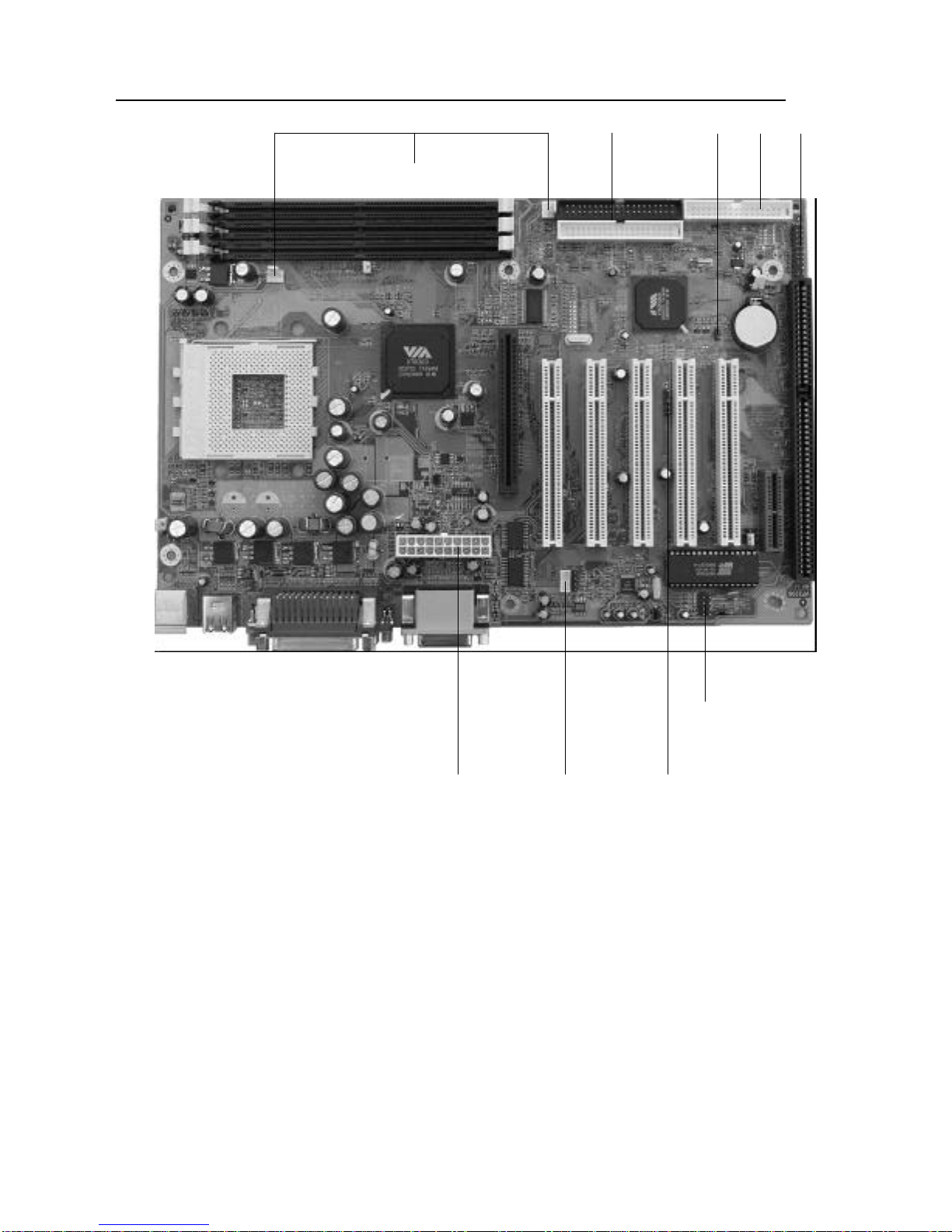
1-3 Main Board Layout

PV 2208 User Manual
8
Chapter 2 Installation Procedures
Warning: Always disconnect the power cord from your computer whenever your
are working on it. Failure to do so may result in sensitive electronic
components being damaged.
Note: Always ground yourself to remove any static charge before touching any
electronic components in the system. Place all electronic components on
a static free surface or in an anti static bag when they are not being
handled or installed in the computer.
User adjustable jumpers have been installed on the mainboard to allow for user
configuration of the mainboard to meet your specific needs. Information pertaining to
all jumper configurations has been included in the following chapter.
To correctly install your mainboard into your computer, use the following steps:
1. Set the jumpers on your mainboard to the correct configuration.
2. Install RAM.
3. Install CPU & Fan.
4. Install expansion cards.
5. Locate and install external devices.
6. Perform power on procedures.
PV 2208 User Manual
9
2-1 Setting System Jumpers
Warning: Incorrect jumper configurations may damage the CPU, the mainboard
and other sensitive electronic components. It is advisable to consult
product literature before configuring the jumpers on the PV 2208
mainboard.
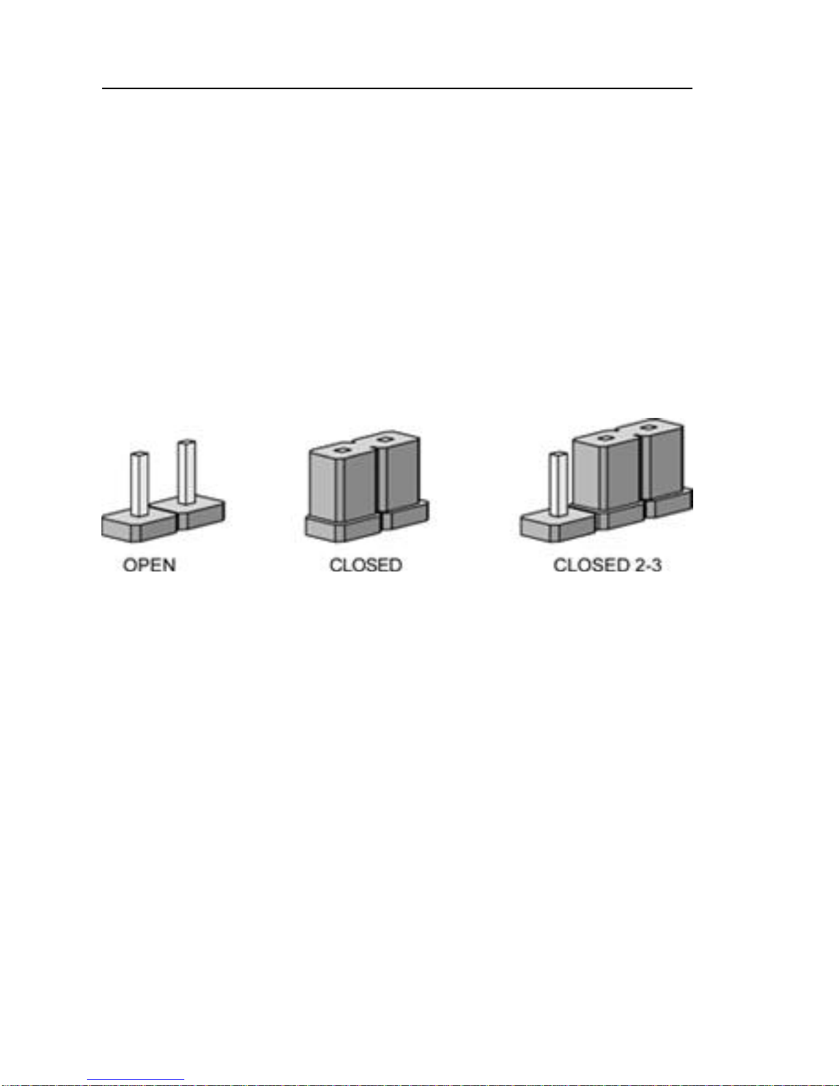
The PV 2208 mainboard has four jumpers (JP1, JP2, JP3 & JP4) that enable the user
to set-up the mainboard for optimal performance based on their computing needs. A
jumper is the simplest type of electrical switch. It consists of two metal pins and a
metal clip, which is covered by a plastic cover. You may set up you mainboard to
match the needs of your applications by setting the jumpers. To open a jumper, you
remove the clip. To close a jumper, you connect the pins by using the clip.
The jumper settings are presented above.
Clearing The CMOS:
In order to clear the data stored in the CMOS, first turn off the computer and
remove the power cord. Next, ground yourself and locate JP2 on you
mainboard. Then remove the jumper from pins 2 & 3 and place the jumper on
pins 1 & 2 (3V battery back up). Reattach the power cord and restart the
computer.
PV 2208 User Manual
10
2-2 System Memory
The PV 2208 mainboard can support up to 1.5GB of 100MHz or 133Mhz SDRAM.
Installing memory modules requires no system setup what so ever.
Note:
1. The PV 2208 mainboard can only accommodate DIMMs (Dual Inline
Memory Modules). The DIMM sockets on the PV 2208 are for 3.3V (power
level) SDRAM (Synchronous Dynamic Random Access Memory).
2. Due to the strict timing issues involved under this speed, you must insure that
SDRAM is 100/133MHz compliant.
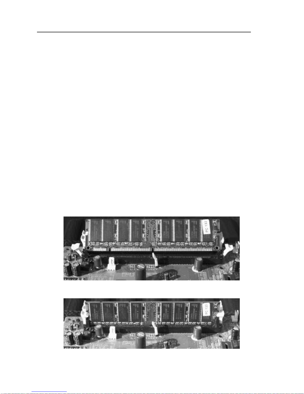
Installing System Memory
Insert the DIMM as illustrated in the diagram below. Due to the number of pins
between each of the breaks in the module, the DIMM will only fit into the socket one
way. Please insure that the DIMMs that you are using are 3.3V.
To insert the DIMM into the socket, first the DIMM socket levers (the white levers on
either side of the DIMM socket) must be pushed out away from the socket itself. Then
line up the pins on the DIMM to the corresponding pins in the socket. Push the DIMM
securely down into the socket. As the DIMM slides into the socket, the DIMM socket
levers will snap back in toward the DIMM socket securing the DIMM into place.

PV 2208 User Manual
11
2-3 CPU (Central Processing Unit)
The PV 2208 mainboard is a Socket A mainboard. This refers to 462-pin socket that
the board utilizes to accommodate the CPU. The CPU that is in use or you are going to
use should have a cooling fan attached to it to prevent overheating. If your CPU does
not have a fan, please ensure that you purchase and install a CPU cooling fan prior to
turning on your computer for the first time. After installing the cooling fan, make sure
that there is sufficient airflow around the fan to ensure proper cooling. If there is
insufficient air circulation, the processor can overheat and damage not only the CPU,
but also the mainboard.
Caution: The faster your processor is, the more heat it. A suitable cooling fan for
your specific processor must be used.
PV 2208 User Manual
12
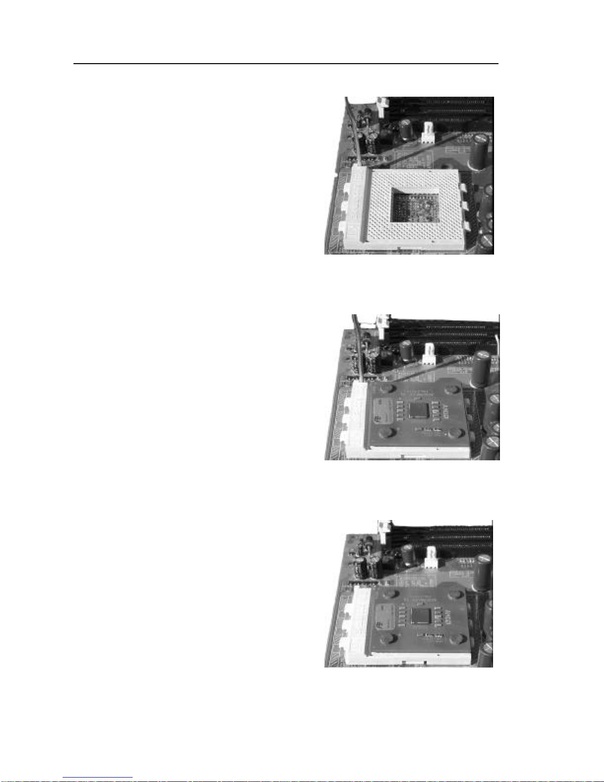
CPU Installation Procedures
Step1
Open the socket by raising the
actuation lever.
Step 2
Insert the processor. Ensure proper pin
1 orientation by aligning the FC-PGA
corner marking with the socket corner
closest to the actuation arm tip. The
pin field is keyed to prevent mis-
oriented insertion. Do not force the
processor into the socket. If it does not
go in easily, check for mis-orientation
and debris. Make sure the processor is
fully inserted into the socket on all
sides.
Step 3
Close the socket by closing the tuation
lever.

PV 2208 User Manual
13
2-4 Expansion Cards
Warning: Always disconnect the power cord from your computer whenever your
are working on it. Failure to do so may result in sensitive electronic
components being damaged.
Note: Always ground yourself to remove any static charge before touching any
electronic components in the system. Place all electronic components on
a static free surface or in an anti static bag when they are not being
handled or installed in the computer.
The PV 2208 mainboard has 1 AGP, 5 PCI, 1 ISA & 1 AMR expansion slots. To
install an AGP, PCI, ISA or AMR card, please follow the following procedure:
1. Read any documentation that is accompanied with the expansion card.
2. Ensure that any hardware setup such as jumper configuration has been
completed.
3. Remove the computer cover and unscrew and remove the bracket plate
that accompanies the slot to which you want to install the expansion card
into.
4. With great care align the card connectors with the socket connectors and
press the expansion card firmly into place.
5. Secure the card by replacing the screw from the bracket plate. Replace
the computer cover.
6. Perform any BIOS updating necessary.
7. Install any drivers and/or software necessary for the operation of your
expansion card.
PV 2208 User Manual
14
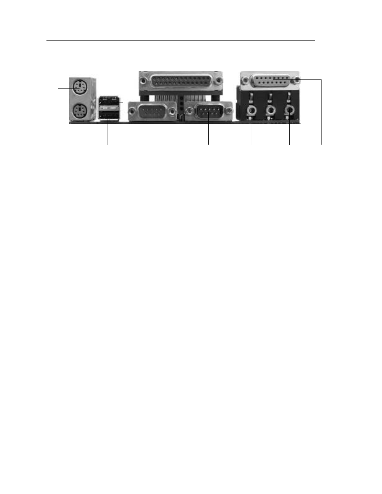
2-5 External Connectors
1
2
3
4
5A
5B
6
7A
7B
7C
1. PS/2 Mouse Connector:
The PV 2208 mainboard has a built in mini-DIN mouse connector, which is
designed for a PS/2 style mouse.
2. PS/2 Keyboard Connector:
The PV 2208 mainboard has a built in mini-DIN keyboard connector, which is
designed for a PS/2 style keyboard. This connector will not accommodate a
standard AT (large-DIN) keyboard plug.
3. USB Ports 1 & 2 (Universal Serial BUS):
The PV 2208 mainboard has two build in USB ports for connecting USB devices.
4. Parallel Port Connector:
The PV 2208 mainboard has a built in parallel port, which is used to connect the
computer to the printer.
5. Serial Ports COM1 & COM2:
The PV 2208 mainboard has two built in serial ports, the COM1 and COM2 ports.
A. The COM1 port is ready for a mouse or other serial devices.
B. The COM2 port is ready for a mouse or other serial devices.
6. Optional Joystick/MIDI Connector:
The PV 2208 mainboard has an optional built in Joystick/MIDI connector that
allows you to connect joysticks or game pads to your computer. You can also use
this connector for connecting MIDI devices for playing and editing audio.
7. Optional Audio Port Connectors:
The PV 2208 mainboard has three optional built in 1/8” Game-Audio connectors.
A. The optional Line Out is designed to be connected to either
headphones or powered speakers.
B. The optional Line In is designed to allow your computer to record or
play from external sources such as CD player or other audio source.
C. The optional Mic In is designed to be connected to a microphone to
allow the inputting of voices into the system.
PV 2208 User Manual
15
8
9
10
11
12
13
19
18
20
8. Primary/Secondary IDE Connectors (IDE1 & IDE2):
The PV 2208 mainboard has two built in Ultra DMA/100 IDE connectors that
support up to four IDE devices such as Hard Disk Drives, CD Drives, Tape
Backups and other IDE devices. In order to connect your mainboard to an IDE
device you must use an Ultra DMA/100 IDE cable, which was provided to you
with your mainboard. If you are installing two hard disks, you must configure the
second drive to slave mode by setting its jumper accordingly. Please refer to you
hard disk documentation for correct jumper settings.

PV 2208 User Manual
16
9. Floppy Disk Drive Connector (FDC):
The PV 2208 mainboard has a built in Floppy Disk Drive Connector that allows
up to two floppy drives to be connected to the mainboard. In order to connect
your mainboard to a floppy drive you must connect it using the floppy disk drive
cable that was provided to you with your mainboard. The drive A:\should be
connected at the end of the cable and if you have a second floppy drive, drive B:\
should be connected in the middle of the cable.
10. Wake On LAN (WOL)/Wake On Modem (WOM) Connector (WOL1):
The PV 22008 mainboard has a built in Wake On LAN and Wake On Modem
connector. This connector allows the system to power up when a wakeup packet
or signal is received through the LAN/modem card.
11. USB2 PIN Header (Universal Serial Bus 2):
The PV 2208 mainboard has a built in connector for two additional USB ports by
means of a USB PIN Header.
12. CPU/AGP Fan Connectors (Fan1 & Fan2):
The PV 2208 mainboard has two built in fan connectors for connecting up to two
cooling fans to the mainboard. One fan should always be used for cooling your
CPU, while another fan connector could be utilized for an AGP card cooling fan
or a chassis fan or not at all. Depending upon the type of fan that you have, the
wiring and the plug may be different. Usually, but not always, the red is positive,
while the black is ground. Connect the fan plug to the board while ensuring to
connect the positive pin to the positive pin and the negative pin to the negative
pin.
FOR CONNECTORS 13 –17 SEE NEXT PAGE
18. Internal Audio Connectors:
These two connectors allow direct stereo input into your mainboard from such
sources as a CD-ROM, a TV-Tuner and/or an MPEG Card.
19. ATX Power Connector:
This connector connects the PV 2208 mainboard to the ATX power supply in
your computers chassis. The ATX power connector can only be inserted one way,
so to insert the ATX power connector, line up the pins and push down firmly.
20. IR1 (IR Pin Header):
The PV 2208 has an IR (Infrared) connector for use with IR modules. You can
connect your mainboard to an optional wireless IR transmitting and receiving
module. The IR function must be configured using the BIOS.

PV 2208 User Manual
17
16
13
14
15
17
13. Power LED Lead:
The Power LED indicates whether the system is ON or OFF. When the computer
is ON, the LED will light up and when the computer is OFF, the LED will remain
unlit.
14. System Warning Speaker Connector:
This 4-pin connector connects the mainboard to the case speaker.
15. ATX Power Switch Lead:
The ATX Power Switch controls the power status of the computer. A momentary
switch is connected to this lead and pushing this button once while the computer
is off will power the computer on and pushing the button for more than 4 seconds
while the system is powered on will power the computer off. The Power LED
shows the ON/OFF status of the computer.
16. HDD LED Lead:
This connector is connected to the IDE activity LED. This LED illuminates
whenever there is any read/write activity occurring on any of the primary or
secondary IDE devices.
17. Reset Switch Lead:
This connector is connected to the Reset switch on the outside of your computer
case. This switch is designed for rebooting your computer without having to turn
the power off and then back on again. This is the preferred method of rebooting
your computer over turning the power off and then back on again as it will extend
the life of your power supply.

PV 2208 User Manual
18
2-6 Power Connection Procedures
Once all the connections on the mainboard have been made, ensure that all other
connections are made in the rest of the system and replace the computer case cover.
Turn all switches off and plug the computer power cord back into the back of the
computer. Check to see that the other end of your power cord is properly connected to
the wall via a surge protector. Now you may begin to power up you system in this
order:
1. Your monitor.
2. Your external devices.
3. Your computers ATX power supply.
4. Your computers power button.
At this point your Power LED on the front on your case should illuminate. The system
will now be running its Power On Self Tests. During the self-tests, various messages
will appear on you monitor. If you do not receive any of these messages and if your
computer does not appear to powering up properly within 30 seconds, power the
system off. Check that all cables are connected and that the jumper settings are correct
and/or contact your retailer for further assistance.
To power your computer off, first you must exit or shut down your operating system
before pushing the power button down for four seconds. If you are using Windows 95
or a newer Windows version, left click on the Start button and select Shut Down and
then once again select Shut Down The Computer. At this point your screen will
display You can now safely turn OFF your computer. At this point you may power off
your computer by depressing the power button for four seconds or your computer will
simply power itself off automatically.

PV 2208 User Manual
19
Chapter 3 AWARD BIOS Setup
3-1 Introduction
The Award(tm) Setup program allows users to modify the basic ROM BIOS system
configuration. Stored in battery-backed RAM this special information retains the
Setup information while powered off.
In your computer system's ROM (Read Only Memory) is an Award BIOS™ custom
version of an industry standard BIOS. It supports all processors by Intel/Cyrix/AMD
in standard IBM-AT compatible input output Systems. Disk drives and serial ports
receive critical low-level support for standard devices from the BIOS. Your Award
BIOS™ is optimized by adding important nonstandard, features such as special
support, and for detailed fine-tuning of the chipset controlling the entire system as
well as virus and password protection. The rest of this manual is intended to guide
you through the process of configuring your system using setup.
Starting Setup
Activating your computer will automatically initiate the Award BIOS™, it will then
begin to check and configure your system by reading information in the CMOS. Once
complete, the computers' operating system will be loaded and begin to take over the
setup process. There are two different ways to begin the setup program while the
BIOS is still in control of the computer, they are both listed below:
1. You can press the <Del> key right after the system has been powered on,
or
2. Wait for the POST (Power on Self-Test) message to appear at the bottom
of the screen then press the <Del> key. It will read as follows: Press
DEL to enter SETUP
If while the system is powering on you miss the message, and you need to restart you
can do so by pressing the RESET button on the computers case, powering the system
off via the ON/OFF button or, pressing <Ctrl>, <Alt> and <Del> key at the same time.
If you miss the aforementioned opportunities to enter the setup an error message will
display letting you know the system did not boot, the following will appear: PRESS
F1 TO CONTINUE, OR DEL TO ENTER SETUP

PV 2208 User Manual
20
Using Setup
Navigating through the menu bar used left and right arrows to choose menu you want
to be in. The main keys you will need to navigate the setup are as follows:
Key Function
Enter To select highlighted item
Page Up To change entries, increase the numeric value
Page Down To change entries, decrease the numeric value
Esc To quit and not save changes in the CMOS Status
Page Setup Menu and Option Setup Menu –quit page and return to
Main Menu
Up Arrow Move to previous item
Down Arrow Move to next item
Left Arrow Move to the item on the left hand
Right Arrow Move to the item on the right hand
+ Key Increase the numeric values, or makes changes
-Key Decrease the numeric values, or makes changes
F1 Key General help, only for Status Pages Setup Menu and Option Page
Setup Page
(Shift) F2 Key Change color from 16, F2 to select color forward, (Shift) F2 to
select color back
F3 Key Calendar, only for Status Page Setup Menu
F4 Key Reserved
F5 Key Restore the previous CMOS value from CMOS only for Option
Page Setup Menu
F6 Key Load the default CMOS value from BIOS default table, for only
Options Page Setup Menu
F7 Key Load the default
F8 Key Reserved
F9 Key Reserved
F10 Key Save all the CMOS changes, only from the Main Menu
To display sub menu
Use the arrow keys to manipulate the cursor to the sub menu of your choice, then
press enter.
Getting Help
Press F1 to in-list a help window, this window describes a few possible solutions and
key to press and the selections for the highlighted item. To exit the Help Window
press <Esc> or the F1 key again.
Table of contents


