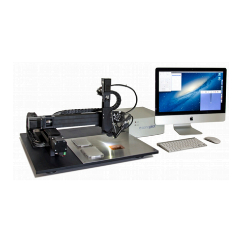
SONOPLOT MICROPLOTTER II User manual

MICROPLOTTER™ II
MANUAL
REVISION 2.2

SONOPLOT, INC.
3030 LAURA LANE, SUITE 120
MIDDLETON, WI 53562
(608) 824-9311
CONTACT@SONOPLOT.COM!
2

CONTENTS
Introduction 6
Ultrasonic fluid dispensing 6
Surface height sensing 8
Precision robotic positioner 8
Installation 9
Unpacking and setup 9
Positioning system 9
Connecting the system to a computer 11
Installing the SonoGuide software 13
Loading a dispenser cartridge 17
Powering on the system 18
Sample Application 20
One-component oligonucleotide microarray 20
Wires from nanometallic inks 28
SonoGuide 30
Overview 30
Main interface 30
Directional controls 32
Toolbar items 33
Saving positions 34
Robotic positioner settings 35
Printing patterns 37
Camera display 40
Camera settings 41
Dispenser control 43
Dispenser calibration 45
Solution well locations 46
Surface cant calibration 49
Rotational calibration 50
Diagnostics 51
Useful Keyboard Shortcuts 54
Troubleshooting 55
Technical Specifications 58
3

Copyright
Copyright ©2015 SonoPlot, Inc. All rights reserved.
Trademarks and Patents
SonoPlot, the SonoPlot logo, SonoDraw, SonoGuide, and Microplotter, among others, are
trademarks of SonoPlot, Inc. in the United States and other countries. Other parties’ trademarks
or service marks are the property of their respective owners and should be treated as such. The
Microplotter products and accessories are protected by one or more of the following U.S.
Patents: 6874699, 7467751.
5


INTRODUCTION
Congratulations on your purchase of a SonoPlot Microplotter instrument! A Microplotter system
is a leading-edge tool for the fabrication of biological microarrays, polymer electronics, or any
other application that requires precise and accurate dispensing of extremely small liquid
volumes. It can dispense picoliters of a wide variety of solutions onto almost any planar surface
in discrete spots or continuous traces such as lines or arcs.
This document will guide you through the installation and setup process for your Microplotter
system in Chapter 2, followed by walkthroughs of simple dispensing applications in Chapter 3.
The software package that controls the dispenser and automate the dispensing of patterns on a
surface, SonoGuide, will be described in Chapters 4. Solutions to common problems will be
listed in Chapter 5 and the technical specifications will be described in detail in Chapter 6. How
to refurbish a dispenser will be covered in Chapter 7.
Before that, however, it would be appropriate to describe the fundamental operating principles of
a Microplotter instrument.
Ultrasonic fluid dispensing
A Microplotter instrument is capable of applying picoliters of fluid to a surface in order to create
features as small as 20 micrometers (microns) wide due to its use of a novel form of fluid
ejection based on ultrasonic pumping.
The dispenser at the core of a Microplotter system is composed of a hollow, tapered glass
needle attached to a piezoelectric element. When an alternating current is supplied to the
piezoelectric, it vibrates. At certain frequencies, the resonant frequencies of the dispenser, a
pumping action occurs within the needle or, if the amplitudes of vibration are high enough, fluid
is sprayed out of the end of the needle. This electronically controlled pumping action makes it
possible for microscale fluid features to be put down by a Microplotter instrument. The spraying
action allows for rapid switching between different solutions while minimizing cross-
contamination.
To dispense a spot of fluid on a surface, a Microplotter dispense head is first loaded with fluid
and then brought near the surface. The ultrasonic pumping action is activated by the controlling
computer either automatically when running a preset pattern or manually by the user. This
pumping causes the fluid meniscus at the tip of the dispenser to bow outward. When the
dispenser is brought close enough to the surface, a droplet will be touched off. The ultrasonics
are then deactivated and the dispenser is retracted from the surface.
6
1

Fluid deposition via ultrasonic pumping
A Microplotter system also has the unique capability of dispensing continuous lines. This is
accomplished by starting as if to create a spot on a surface, but not deactivating the dispenser
after fluid contact has been made with the surface. Instead, the dispenser is moved along the
surface in a straight line, leaving behind a smooth line wherever it passes. Only when the line is
finished is the dispenser deactivated and retracted from the surface.
Aqueous solution being deposited in a 50 micron diameter spot
7

Surface height sensing
The detection of the surface height is handled by an electronic feedback system that
uses changes in the vibrational properties of the dispenser to detect whether or not it
has contacted a physical object, no matter how gently. This surface sensing capability
allows for the cant of a surface to be calibrated, so that the control software can
maintain a consistent height of the dispenser above the surface for reliable dispensing.
Precision robotic positioner
The Microplotter picoliter dispenser would not be of much use without a precision
positioning system to place that dispenser at select locations, and do so in an
automated fashion. The robotic positioner of the Microplotter system occupies most of
its physical volume, and can move the dispenser over a 31 x 31 x 7 cm volume with a
10 micron resolution in the X, Y, and Z axes. All of this movement is controlled through
the SonoGuide software package (described in Chapter 4) either manually by the user
or automatically through the running of a pattern.
As you read through the following chapters, you will learn how to install, configure, and
operate your Microplotter II instrument in order to take advantage of its unique
capabilities in your line of research or development.
8


INSTALLATION
Unpacking and setup
The Microplotter II instrument will come in one large crate containing the system itself, the
control electronics, and a box of smaller components.
Warning: The positioning system is heavy, and should be lifted by more than one
person. When lifting the system, do not pull on the positioning arm, as this may damage
the stages.
Once unpacked, the system consists of the following components:
•Positioning system, with printhead and optics system already mounted
•iMac control computer (with keyboard and mouse)
•Control electronics
•A box containing cables for attachment of the various components
Additionally, SonoGuide, the primary interface for your Microplotter system, will need to be
installed to a controlling computer.
Positioning system
After unpacking, the first step in the setup process is to move the positioning system into place.
Two people should be able to lift the system from its base and position it so that its feet are
firmly on a table.
Next, place the control electronics box on either side of the system, and connect the cables to
the electronics as follows:
9
2

Power cable
Positioning stage X axis cable
Positioning stage Y axis cable
Positioning stage Z axis cable
10

Connecting the system to a computer
Once the cables have been connected to the electronics box, insert the USB cable from the
electronics box into a USB port on your computer and also insert the USB cable from the CCD
camera to a different USB port on your computer. This step is shown below on a Mac computer.
The process is the same for a Windows computer.
USB cable to control computer
RJ11 cable to dispenser
11

If your system comes with a relay controller within the control electronics box (an optional
accessory for triggering external devices), connect the USB cable for that to the computer and
connect the power leads to the appropriate terminals on the device to be controlled. Finally, plug
in the power connectors to the control electronics.
Insert the USB cable for
connecting to the control
electronics.
Insert the USB cable
from the CCD camera.
12

Installing the SonoGuide software
The SonoGuide software is available on both the MacOS platform and Windows platform.
Follow the steps below to install the SonoGuide software on your computer.
MacOS
Go to www.sonoplot.com/downloads and click on the SonoGuide for Mac link.
Download the SonoGuide.DMG file.
Once downloaded, double click on the DMG file. The SonoGuide Installer window will appear on
the screen:
Drag the SonoGuide icon over to the Applications folder."
SonoGuide has now been installed to your MacOS computer.
13

Select the components to install.
Select where you would like to create SonoGuide’s shortcut.
15

SonoGuide is ready to be installed.
Click Install to start installing SonoGuide.
Once the installer has finished installing SonoGuide, click on Finish.
SonoGuide has been installed and is ready to use.
16

Loading a dispenser cartridge
Warning: Avoid contacting the exposed glass needle to any surface, as even a slight
touch can shatter the fragile tip.
To load a dispenser cartridge, carefully place the
notched side of the dispenser onto the printhead,
as shown.
Plug the RJ-11 cable into the RJ11 adapter.
17

Powering on the system
Once all components have been assembled, the control electronics are plugged in, and the
SonoGuide software has been installed, it is possible to power on the system and start
dispensing. To turn on the control electronics flip the power switch for the control electronics on
the rear left as you face the front of the control box. When the system is powered on, the green
power light and orange COMM light will be illuminated on the front of the box.
Double click on the SonoGuide icon to open the controlling software. SonoGuide, described in
detail in Chapter 4, is your primary interface with a Microplotter system, allowing you to
manually move the positioner, automatically dispense complex patterns, control the dispenser,
and observe and record a digital video feed from a high-magnification CCD that tracks the
dispenser.
SonoGuide
18
Table of contents
Other SONOPLOT Plotter manuals


