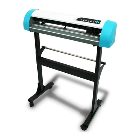
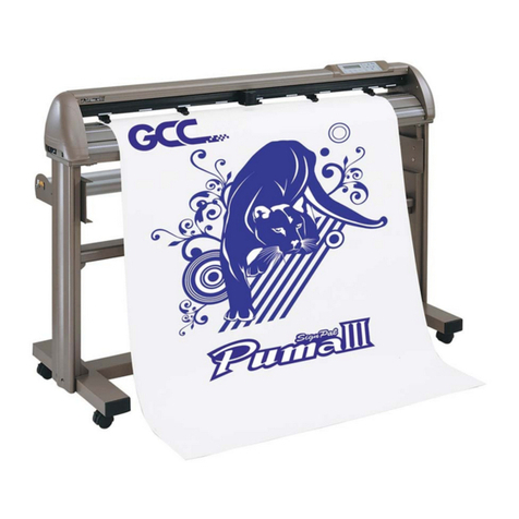
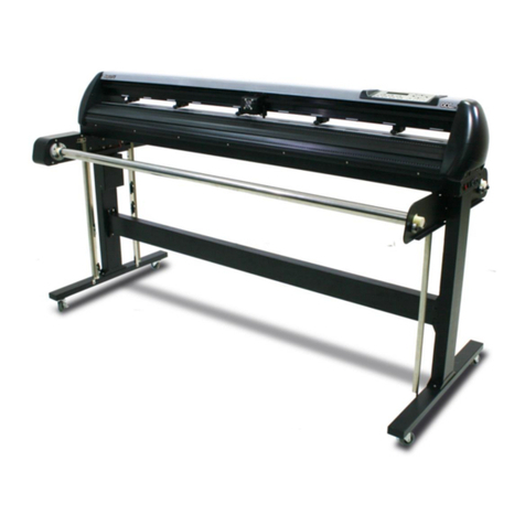
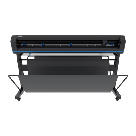
GCC Technologies Puma Series Operating manual

1
Important Safety Information
Safety
Instructions
General
and
Personal
Safety
Precautions
[PERSONAL SAFETY]
For personal safety, observe the following general precautions:
A second person should be
available to disable the system in an emergency.
Wear appropriate protectIIIe gear that fits comfortably.
Do not wear loose-fitting clothes. If you are wearing a long-sleeved shirt, fold the
cuffs up your arm.
Never wear gloves close to moving parts.
Necklaces, ties and scarves should be tucked inside shirts.
Long hair should be covered.
[ELECTRICAL
TOOL
SAFETY]
When using Electrical Tools make sure to:
Use tools that are in good operating order. Any tool that appears electrically or
Mechanically faulty must be labeled and sent immediately for repair.
Make sure that you are electrically insulated when using electrical tools. Wear
rubber-soled shoes and stand on a dry surface.
If, during the use of electrical equipment, you feel an electrical discharge (e.g. a
tickling sensation on your skin) immediately stop using that tool. Label it, and send it for
repair.
[GENERAL SITE SAFETY
REQUIREMEN
TS]
Fire extinguishers must be in working order and within easy reach.
The main power supply switch must be easily accessible.
The system site must be suitably illuminated from all sides.
Before operation, carefully read the warning labels on your Cutting plotter unit as
well as the cautions and warnings in this manual.
Connect the Cutting plotter to a properly grounded power outlet. Make sure the
voltage level of the Cutting plotter matches that of the power source.
Don’t dissemble the unit while system power is on since the power supplies inside
contain high voltage.
Never leave the machine unattended during operation.
Follow the instructions on maintaining and cleaning your system. Not only will this
enable you to utilize your machine efficiently, but it will also ensure that your
machine runs safely.

2
Contents
Important
Safety
Information
.......................................................1
Safety Instructions........................................................................................................ 1
General and Personal Safety Precautions …..................................................................1
Contents
.........................................................................................2
Introduction and Component Overview..........................................................................3
Main Unit Assembly……………................................................................................4
Unit Chassis Assembly .................................................................................................6
Left End Assembly..........................................................................................................7
Right End Assembly ......................................................................................................9
Carriage Assembly without PCB…..............................................................................11
Complete X-motor Assembly........................................................................................13
Y-Axis Idle Pulley Assembly........................................................................................15
Pinch Roller Assembly..................................................................................................17
Grid Drums Assembly...................................................................................................19
Main Beam Assembly………………………………………………………………...21
1. System
Diagram
and
Components
of
Main
Board
................22
1.1 System Diagram………………………………………………………………..23
1.2 Connection of Electrical Components…………………………………………24
Replacement of Pinch Roller Set and Lever Assembly............................................26
Removal and installation of Tool Carriage……………….............................................28
Belt Tension Adjustment……………........................................................................29
2. Maintenance………………………………………………………..30
Removing the Front, Back, End and Top Covers…………………………………..30
Replacing the Pinch Roller Sets…...............................................................................32
Replacing the Tool Carriage………………………………………………………...34
Replacing the Y-Motor................................................................................................36
Replacing the VCM PC Board.....................................................................................38
Main board Connection or Replacement ................................................................…39
Replacement of Fuses ............................................................................................….40
Adjusting the Tool Carriage Transmission Belt...........................................................41
Adjusting the X Motor Tension Belt............................................................................42
Adjusting the Y Motor Tension Belt............................................................................43
3.T
r
oubleshooting…………………………………………………..45
Maintenance Diagnostics.............................................................................................45
How to Begin Maintenance Diagnostics......................................................................46
Diagnostic Test for SRAM and DRAM.......................................................................47
Diagnostic Test for Lever Sensor.................................................................................47
Diagnostic Test for Media Sensor…………………....................................................48
Diagnostic Test for Width Sensor ................................................................................49
Diagnostic Test for Motor Encoder and Tool Holder Encoder ...................................50
Diagnostic Test for Tool Force (VCM).......................................................................51
Diagnostic Test for Motor Movement.........................................................................51
Diagnostic Test for the RS-232 Interface....................................................................53
Problems and Solutions...............................................................................................54
Appendix
………………………………………………………..……57
Spare Parts Reordering Form...............................................................................58

3
Introduction and Component
Overview
This Maintenance Guide provides step-by-step instructions for rep
lacing and maintaining the
components of the Puma Cutting plotter. It also includes a troubleshooting chapter
with some handy hints when problems arise or if the plotter does not operate properly.
This Maintenance Guide provides system diagrams, wiring diagrams and numerous flow
charts detailing the maintenance diagnostics built into the Expert Pro Cutting plotter.
Finally
there is a parts list and spare parts order form for convenience of ordering replacement parts.
For further Tech Support enquiries and assistance please contact the following Email
address:
Tech.support@gcc.com.tw
The following diagrams represent all of the maintainable mechanical and electronic
components of the Expert Pro Cutting Plotter with corresponding parts lists for
convenient identification.
T
o
the
Contents
Page

4
Main
Unit
Assembly 29006178G

5
Item Part Number Part Name Quality
1 24401210G Unit base box 1
2 24402393G Side support left 1
3 24402394G Side support right 1
4 29004688G Main beam assembly 1
5 22800705G Top rail 1
6 22801070G Square Bar 1
7 29001473G Pinch roller assembly 2
8 29004690G Carriage assembly 1
9 22802168G Top cover 1
10 24100499G Left cover 1
11 24100491G Right cover 1
12 24100492G Front platen extension 1
13 24100493G Rear platen extension 1
14 24100333G Lever 1
15 29005498G Main board 1
16 29004692G Control panel assembly 1

6
Unit Chassis Assembly 29004693G
Item Part Number Part Name Quality
1 24401210G Unit base box 1
2 29005498G Main board 1
3 29001488G Power board 1
4 25700075G ON/OFF Power switch 1
5 22300021G Fuse holder 1
6 21800034G AC plug 1

7
Left End Assembly
7
1

8
Item Part Number Part Name Quality
1 29003810G X-Axis Motor Assembly 1
2 24100189G X-Axis actively belt gear 1
3 20600039G X-Axis belt 1
4 24100175G Idle pulley 1
5 24400288G X-motor adjusting bracket 1
6 24400761G X-motor bracket 1
7 22300021G Fuse Holder Type 1

9
Right End Assembly
7
8

10
Item Part Number Part Name Quality
1 24400264G Active pulley’s bracket 1
2 24100176G Active pulley 1
3 22800288G Active pully s shaft 1
4 24400066G Cable basket 1
5 24400265G Y-motor bracket 1
6 29003812G Y Motor Assembly 1
7 24100258G Switch cam 1
8 25700002G Lever switch 1

11
Carriage Assembly without PCB 29002613G
Item Part Number Part Name Quality
1 22802177G Carriage base finishing 1
2 22800769G Right side shaft in tool carriage 1
3 22800765G Left side shaft in tool carriage 1
4 20200085G Blade holder slider bracket
assembly 1
5 29000940G VCM assembly 1
6 20200065G VCM coil 1
7 25500043G Tool carriage spring 2
8 29001467G VCM PCB assembly 1
9 22800838G Blade holder bracket screw 1
10 22800048G Spacer for carriage guide roller 2
11 20700040G Flange bearing 4
12 22801680G Carriage guide roller flute-A 2
13 22800049G Carriage guide roller 2
14 22800411G Spacer for Carriage guide roller 2

12
15 20700029G Bearing 4
16 22800710G Carriage guide roller flute 4
17 22801464G
White spring bracket for carriage
guide roller 2
18 25500041G
Spring for carriage guide roller 4
19 22800717G
Carriage guide roller shaft 2

13
Complete X-motor Assembly 29003820G

14
Item Part Number Part Name Quality
6.1 29003820G Motor assembly 1
6.1.1 29003810G Motor, 1
6.2 24400761G X-motor bracket 1
6.3 24400288G X-motor adjusting bracket 1

15
Y-Axis Idel Pulley Assembly 29003820G

16
Item Part Number Part Name Quality
8.1 29001548G Y-Axis Idle Pulley Assembly 1
8.1.1 24100175G Idle pulley 1
8.1.2 20700038G Bearing 2
8.1.3 22800310G Idle pulley shaft 1
8.1.4 24900006G E-shape retaining ring 4
8.1.5 22801465G White pulley Washer 1
8.1.6 25200345G M3*14 Pan Screw Spring 1
8.1.7 23500004G Nut(M3xt2.4xS5.5) 1
8.2 24400287G Idle pulley Assembly adjusting bracket 1
8.3 24400286G Idle pulley Assembly bracket 1
8.4 25200117G Hexagonal Socket Head including spring &
flat washer 1
8.5 25200157G Hexagonal Socket Head including spring&
flat washer 2

17
Pinch
Roller
Assembly 29001437G
4.
1
8

18
Item
Part Number
Part Name Quality
1 24100285G Pinch roller base 1
2 24100286G Pinch roller arm 1
3 22800310G Lynx Cam Roller 1
4 20200003G Pinch roller wheel 1
5 22800029G Pinch roller shaft 1
6 25500040G Pinch Roller Spring Lynx 2
7 24900006G E-shape retaining ring 4
8 22800294G Pinch roller active arm shaft
Lynx 1

19
Grid Drum Assembly 29005441G

20
Item
Part Number
Part Name Quality
1 22802167G Grid Drum shaft(Puma III-60) 1
2 22800564G Bearing Blocker 2
3 20700039G Bearing L-1910ZZ 5
4 23300362G long drum 50mm 6
5 24100189G X axis actively belt gear 1
This manual suits for next models
2
Table of contents
Other GCC Technologies Plotter manuals

GCC Technologies
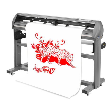
GCC Technologies Jaguar IV Series User manual

GCC Technologies
GCC Technologies EXPERT 24 LX User manual

GCC Technologies
GCC Technologies Jaguar II Series User manual

GCC Technologies
GCC Technologies EXPERT 24 LX User manual

GCC Technologies
GCC Technologies EP-60 User manual

GCC Technologies
GCC Technologies Expert 52 User manual

GCC Technologies
GCC Technologies puma iii series User manual

GCC Technologies
GCC Technologies RX II Series User manual

GCC Technologies
GCC Technologies J5 Series User manual

GCC Technologies
GCC Technologies Jaguar V Series User manual