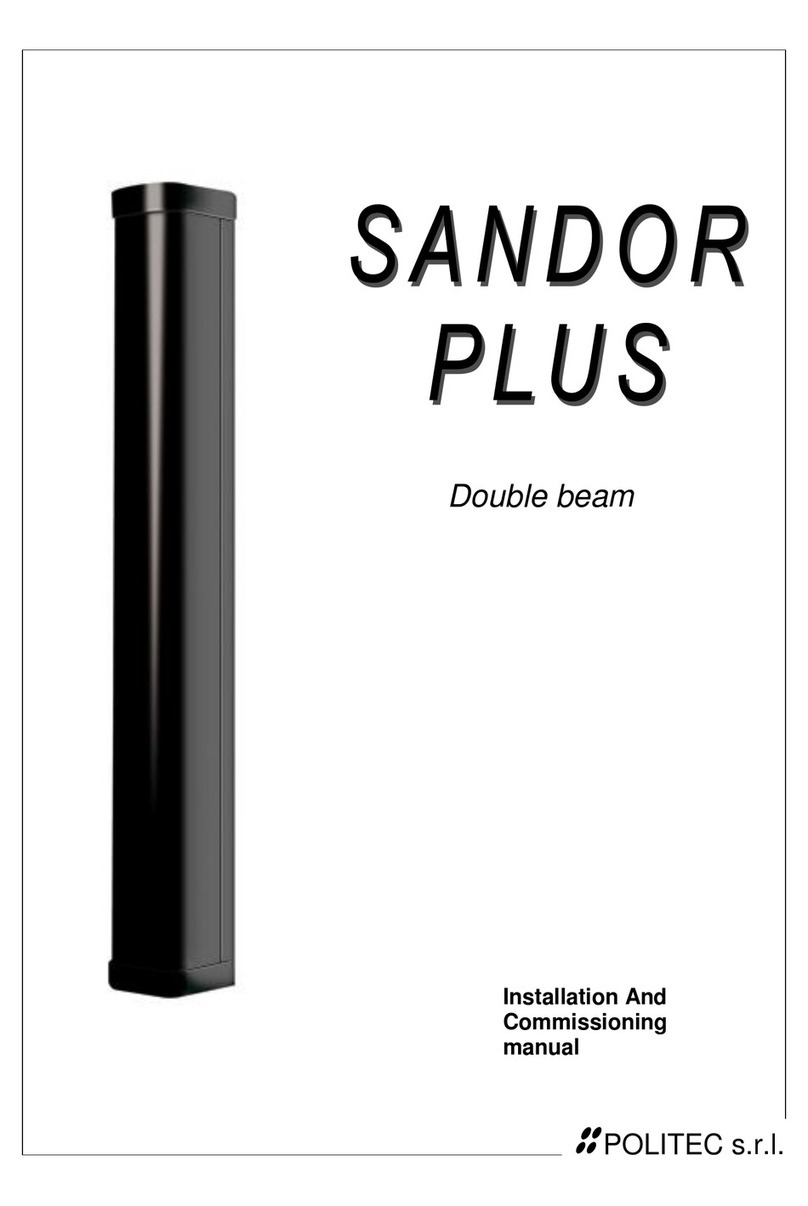
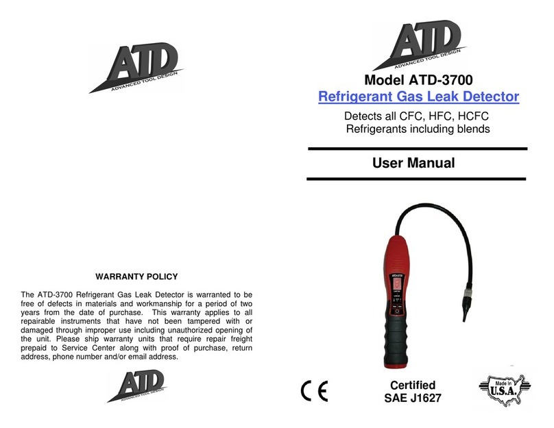
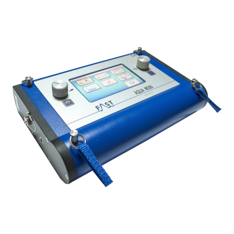
Sonotec SONOCHECK ABD05 Series User manual

Air Bubble Detector
Type
SONOCHECK®ABD05/xx
Operating Manual

© SONOTEC GmbH
All rights reserved.
Revision: 2.1; Date: 2020-07-22
Information is subject to change without notice!

Operating Manual SONOCHECK®ABD05/xx
Page 3 of 40
Revision: 2.1; Date: 2020-07-22
Contents
1Notes on operating manual .................................................................................................................. 5
1.1 General...........................................................................................................................................5
1.2 Symbols used.................................................................................................................................5
2Safety regulations ................................................................................................................................. 6
2.1 User qualifications ..........................................................................................................................6
2.2 General safety information .............................................................................................................6
3Sensor description ................................................................................................................................ 7
3.1 Intended use...................................................................................................................................7
3.2 Construction ...................................................................................................................................7
3.3 Measuring method and functioning ................................................................................................8
3.4 Bubble sensitivity ...........................................................................................................................9
3.5 Sensor software ...........................................................................................................................10
3.6 Settings and default parameters ..................................................................................................10
3.7 Adaption of sensor parameters: ABD Monitor (optional accessories) .........................................12
3.8 Sensor identification.....................................................................................................................12
4Interfaces and outputs........................................................................................................................ 13
4.1 Output ABD-OUT .........................................................................................................................13
4.2 Output specification: default settings and sensor status via LED ................................................13
4.3 Input ABD-IN ................................................................................................................................14
4.4 Serial Interface (UART)................................................................................................................14
5Interface Modes ................................................................................................................................... 15
5.1 Overview interface modes............................................................................................................15
5.2 Interface Mode 0 (default) ............................................................................................................16
5.3 Interface Mode 1 / 2 .....................................................................................................................17
5.4 Interface Mode 3 ..........................................................................................................................18
5.5 Interface Mode 4 / 5 .....................................................................................................................19
5.6 Interface Mode 6 / 7 .....................................................................................................................21
5.7 Interface Mode 8 ..........................................................................................................................23

SONOCHECK®ABD05/xx Operating Manual
Page 4 of 40
Revision: 2.1; Date: 2020-07-22
6Information for the use in medical devices ...................................................................................... 24
6.1 ʻFail-Safe Architectureʼ .................................................................................................................25
6.2 ʻInitial Testʼ – enter boot mode .....................................................................................................25
6.3 ʻBubble Testʼ.................................................................................................................................25
6.4 Response time .............................................................................................................................26
6.5 Indicating the measuring state with the LEDs..............................................................................27
6.6 Watchdog | Voltage monitor 3.3 V ...............................................................................................27
6.7 Safety / Directives ........................................................................................................................28
7Optimal mounting position, installation and coupling .................................................................... 29
7.1 Selecting the correct sensor version: measuring channel and tubing .........................................29
7.2 Defining correct installation position: sensor orientation and bubble sensitivity ..........................30
7.3 Forbidden liquid in the sensor channel: correct coupling and bubble sensitivity .........................31
7.4 Bends in the tube: turbulences and bubble sensitivity.................................................................31
7.5 Mounting of the sensor.................................................................................................................32
7.6 Connecting the Sensor.................................................................................................................32
8Operating the Sensor .......................................................................................................................... 33
8.1 ʻInitial Testʼ after power on or restart............................................................................................33
8.2 Inserting the tube .........................................................................................................................33
8.3 Monitoring sensor during operation .............................................................................................34
8.4 Cleaning and disinfection .............................................................................................................35
9Maintenance, service, troubleshooting and repairs ........................................................................ 36
9.1 Service and troubleshooting.........................................................................................................36
9.2 Repairs .........................................................................................................................................37
10 Disposal................................................................................................................................................ 38
11 Personal notes..................................................................................................................................... 39

Operating Manual SONOCHECK®ABD05/xx
Page 5 of 40
Revision: 2.1; Date: 2020-07-22
1 Notes on operating manual
1.1 General
Thank you for choosing the SONOCHECK®ABD05.
This manual forms part of the SONOCHECK®ABD05 and must be read carefully, before
working with the sensor. It contains all the information needed to ensure proper and efficient
use, along with all the instructions to ensure safe operation of the SONOCHECK®ABD05.
1.2 Symbols used
Hazards or special information is indicated in the following ways:
Warns of imminent threat of danger with very high risk. If not avoided,
it will result in death or serious injury.
Warns of possibly imminent danger with moderate risk. If not avoided,
it could result in death or serious injury.
Warns of danger with low risk. If not avoided, it may result in minor or
moderate injury.
Warns of danger. If not avoided, it may result in material damage.
NOTE!
This paragraph provides information or draws attention to special features.

SONOCHECK®ABD05/xx Operating Manual
Page 6 of 40
Revision: 2.1; Date: 2020-07-22
2 Safety regulations
2.1 User qualifications
Risk of death or severe injury.
The SONOCHECK®ABD05 must only be installed and operated by users
who have read and understood the entire content of operating manual.
Ensure to read all safety regulations below and the special
regularities for the use in medical devices (see chapter 6).
2.2 General safety information
The SONOCHECK®ABD05 is a state of the art product that complies with all applicable safety
regulations. The sensor is factory tested and is delivered in a safe condition for operation. For
the use in medical devices (MDEV) see the special regularities in chapter 6. The following
general safety instructions apply:
Severe measurement error with high risk for patient safety possible.
Liquid in the measuring channel may conduct ultrasound. In this case the
detection of bubbles, empty tube or missing tube may fail.
During operation must never be any liquid medium in the sensor
channel. Ensure, that sensor and the measuring channel are always dry and
clean and that the associated tubing stays intact during sensor operation.
Risk of death or severe injury. Incorrect installation and use of the
SONOCHECK®ABD05 sensor and its components can present a hazard
for the user and the patient, if it is integrated in a medical device.
•The integrator is responsible for the legal compliance of the
SONOCHECK®ABD05 installation and its documentation.
•Observe all requirements and conditions specified in the ‘Technical Data
Sheet’. It is forbidden to exceed or fall below the listed limits – even for a
short period.
•The SONOCHECK®ABD05 must never been immersed.
Sensor – especially sensor channel – must be kept dry and clean.
•The SONOCHECK®ABD05 must only be exposed to a minimal risk
of mechanical damage. In other cases, the sensor must be protected
against mechanical influences. Avoid any pulling or torsion movements
on tube during operation.
•If there is malfunction or damage, or if there is a suspicion that the sensor
is no longer functioning properly, take it out of operation immediately.
•The sensor must never be opened. It does not contain any user-
serviceable parts.
•Any kind of sensor modification is prohibited.

Operating Manual SONOCHECK®ABD05/xx
Page 7 of 40
Revision: 2.1; Date: 2020-07-22
3 Sensor description
3.1 Intended use
The air bubble detector (ABD) SONOCHECK®ABD05 is used to detect air and gas bubbles or foam
in flexible plastic tubes filled with liquids like blood, blood plasma, water or saline solution. In medical
devices the sensor is intended to prevent air infusions which could lead to an endangerment of
patient. The sensor has no contact with the liquid and is suited for disposable tubes.
The SONOCHECK®ABD05 is designed as a component for fixed installation in machines and
equipment e.g. machines for blood treatment, injectors or dialysis machines and is mechanically
and electrically incorporated into the controller.
The sensor can be used in various environments such as blood component collection centers,
catheter laboratory, OR, emergency room, intensive care unit, CT environment as well as for
inter- and intra-hospital transportation. Furthermore, it is possible to use the sensors in
ambulances or for emergency operations outside clinical environments.
Any misuse (e.g. as hose clamp or butterfly valve) as well as any use other than the designated
- is prohibited and can result in death (depending on the application), serious injury or damage
to property. The SONOTEC GmbH accepts no liability for damage, including to third parties,
caused by improper handling of the sensor.
3.2 Construction
The sensor consists of the measuring cell and connected circuit boards with the evaluation
electronics. The measuring cell is an integrative part of the housing. The channel width is
adjusted to the type of the tube. The exact sensor design depends on the diameter, the
hardness and, where required, the liquid medium. Two designs are available:
•Rectangular design
•Circular design
Figure 1: Version with rectangular design (view from side and below) and version with circular design (view from side)
For the specifications (different measuring channels) see the ‘Technical Data Sheet’.
In case of very small tubes or tubes with a very low wall thickness (less than 10 % of the outer
diameter) a cover is necessary to press the tube firmly on the right position. A different sensor
series is available for these applications. Contact our service as well for customized adaptations.

SONOCHECK®ABD05/xx Operating Manual
3 Sensor description
Page 8 of 40
Revision: 2.1; Date: 2020-07-22
3.3 Measuring method and functioning
An ultrasound method based on short, high-frequency pulses is used for the measurement.
When liquid is in the tube, the ultrasonic signal passes through the tube to the receiver.
The intensity of the ultrasound transmitted into the liquid is so low, that no biological effect can
occur. This was tested and confirmed with different fluids, including human blood.
Figure 2: Sensor design and function [symbolic representation]
The maximum value of the received signal amplitude is recorded in a defined period.
Bubbles in the liquid stream result in a reduction of the signal as the ultrasound is
significantly attenuated by air. So if there is a bubble in the measuring path, the proportion of
ultrasound that reaches the receiver is considerably lower – how much depends on the bubble
size as well.
The integrated electronics of the sensor evaluates the amplitude of the received signal and
sets the output accordingly.
The sensor includes 3 LEDs in colors red, green, and blue at the bottom of channel to
indicate the state of measuring. These LEDs are freely configurable. For default settings see
chapter 4.2 Output specification: default settings and sensor status via LED.
Sensor housing with integrated electronics
3x LED in the measuring
channel
Ceramics (Sender
)
Detected air bubble
Tube filled with liquid
Ultrasonic signal
[symbolized by the blue wavy lines]
passing the measuring channel
Ceramics (Receiver)

Operating Manual SONOCHECK®ABD05/xx
3 Sensor description
Page 9 of 40
Revision: 2.1; Date: 2020-07-22
3.4 Bubble sensitivity
The bubble sensitivity of the sensor depends on the diameter of the tubing, the mounting
position of the sensor and on the correct coupling. Bubbles with a diameter larger than 30 % ...
50 % of the inner diameter of the tubing will be detected.
Observe chapter 7 Optimal mounting position, installation for correct installation.
When the sensor is installed as recommended, bubbles with the following size can be detected:
Sensor type Tubing Bubble Detection: Ø and Volume
SONOCHECK®
Material Outer Ø Inner Ø
ABD05.50 /
ABD05.51 PVC 4.0 mm 1.6 mm
mostly > 1.5 mm 2 µl
reliably > 2.0 mm 4 µl
ABD05.52 /
ABD05.53 PVC 6.8 mm 4.3 mm
mostly > 2.0 mm 4 µl
reliably > 3.5 mm 20 µl
ABD05.54 /
ABD05.55
PVC
Silicone
2.8 mm
3.0 mm
2.0 mm
1.0 mm
mostly > 1.2 mm 1.0 µl
reliably > 1.5 mm 1.5 µl
ABD05.56 PVC 2.4 mm 0.8 mm reliably > 1.0 mm 0.5 µl
ABD05.57 PVC 5.5 mm 3.5 mm
mostly > 2.0 mm 4 µl
reliably > 2.9 mm 10 µl
Table 1: Bubble sensitivity depending on sensor type

SONOCHECK®ABD05/xx Operating Manual
3 Sensor description
Page 10 of 40
Revision: 2.1; Date: 2020-07-22
3.5 Sensor software
The sensor software is structured into 2 modules. These modules are strictly separated and
operate alternately. For more detailed description of modes contact our support.
Module Safety
class.
Operational
mode
Function
Main C Start mode After power on or on restart the ‘Init Interval’ is
started. In this period the sensors acts to
commands of serial interface (see notes to input
ABD-IN).
After ‘Init Interval’ the ‘Initial Test’ will be
performed.
Both, ‘Init Interval’ and ‘Initial Test’, take approx.
1.5 s. Afterwards ‘Normal Mode’ will be started.
Normal mode Measuring and detection of bubbles
Cyclical Self-Test
Output of result
Boot A Boot mode Service
Adjusting settings
Updating of software
Table 2: Modules in Software
3.6 Settings and default parameters
Default settings are archived in files. The settings as shown in the figures on the following
page (screenshots of ABD Monitor, optional accessories) are similar for the entire family
ABD05.xx, V1.43.
Deviating from this are the parameters for adjusting the gate (ABD Monitor settings: tab ‘Page 1’)
and the CRC (tab ‘Page 2’). Please find the default parameters in table.
Sensor Gate begin Gate width CRC
ABD05.50 | ABD05.51 | ABD05.52 | ABD05.53
3.0 µs
6.0 µs $4C37
ABD05.54 | ABD05.55 | ABD05.56 1.0 µs $C735
ABD05.57 | ABD05.60 | ABD05.62 6.0 µs $4C37
Table 3: Default Settings

Operating Manual SONOCHECK®ABD05/xx
3 Sensor description
Page 11 of 40
Revision: 2.1; Date: 2020-07-22
Figure 3 | 4: Settings for sensor SONOCHECK®ABD05.50 (ABD05.51 … ABD05.57 / ABD05.60 / ABD05.62 are similar)

SONOCHECK®ABD05/xx Operating Manual
3 Sensor description
Page 12 of 40
Revision: 2.1; Date: 2020-07-22
3.7 Adaption of sensor parameters: ABD Monitor (optional accessories)
The software ABD Monitor (see screenshots last page) displays measured data in real time,
stores the data of a predefined period and allows for a detailed analysis of the sensor
performance. Parameter settings can be tested and assessed instantly. Integration of the
sensor into MDEV, troubleshooting or fine tuning are supported as well. (see as well chapter 9
page 36). Contact our service.
3.8 Sensor identification
Identification of sensor can be read by serial commands in Interface Mode 3, resp. in Boot
Mode. For detailed information see ‘Description of serial interface’.
Identification Value [dec] Meaning Description
DeviceType 20 Air Bubble Detector Kind of sensor
SensorType 05 ABD05.xx Type of sensor family
SensorSubType 50 ... 57 /
60 / 62
ABD05.50 … 57 /
ABD05.60 / 62
Subtype of sensor in its family
HW 2 Type of board Board ABD05_09/ _10
FW 143 V01.43 Version of Software
(main version)
VersionCode 41 ABD05.xx / V1.43 Short code for sensor type
including version of hardware
and software
SN 0 ... 65535 e.g. 10001 Serial Number
Model 0 HW V1.0 Code for variant of sensor
Year 15 ... e.g. 15 = 2015 Year of manufacturing
MCUType 330 C8051F330 Code for type of MCU on board
BootVersion 4 board
ABD05_09/_10
Code for version of boot loader
BootType 01 boot loader written
for MCU family
8051
Code for type of boot loader
Table 4: Modules in Software

Operating Manual SONOCHECK®ABD05/xx
Page 13 of 40
Revision: 2.1; Date: 2020-07-22
4 Interfaces and outputs
The configuration of the sensor can be adjusted to customer requirements. For example, the
output can be configured as switching output or as serial output.
Tools for the adjustment of the sensor configuration are available as optional accessories.
For the sensor use in medical devices see as well the details in chapter ‘6 Information for the
use in medical devices’.
4.1 Output ABD-OUT
The result of bubble detection is communicated to the machine depending on sensor parameter
‘interface mode’, either via:
•Switching output (default)
•Serial output: coded data about bubble size and alarms in frames, repetition rate = 1 ms
•Pulse width modulated signal (PWM): pulse width coded information about bubble size and
alarms, period of signal = 1 ms
The output is tested using a read back line during ‘Initial Test’. After restart the entire test
procedure of ‘Initial Test’ is performed. These tests include test of watchdog and output
ABD-OUT. Sleep failures or other second failure will be recognized.
4.2 Output specification: default settings and sensor status via LED
The default configuration of the output ABD-OUT is switching output with the following
specification:
Condition Signal at output
(H/L: TTL output)
LED
Air/bubble H Red
Liquid L Green
Internal error (self-test) H Blue
Table 5: Output specification (default)
The LEDs can be assigned to internal events, like bubble, fault or liquid individually. The LEDs
can be remote controlled by the MDEV (in Mode 0/ 1/ 2/ 8 only). The LEDs are intended to
support the user during treatment with sensor status information, but must not be considered as
optical alarm messaging.

SONOCHECK®ABD05/xx Operating Manual
4 Interfaces and outputs
Page 14 of 40
Revision: 2.1; Date: 2020-07-22
4.3 Input ABD-IN
The sensor provides an input ABD-IN. It is used as serial input to control the sensor
(e.g. remote control of LED) and for service (e.g. entering ‘Boot Mode’). This input can be used
as digital input to release a ʻBubble Testʼ.
4.4 Serial Interface (UART)
The sensor provides UART, which is connected to ‘ABD-OUT’ as Tx and ‘ABD-IN’ as Rx.
In ‘Normal Mode’ the UART is enabled on disabled depending on configured Interface Mode.
If enabled, the UART is initialized to:
Baud rate 115,200 kBaud / 1 stop bit / no parity / no handshaking.
Independent of the ‘interface mode’ of the sensor, the UART is always enabled:
•For 1 second after power on or after restart (during ‘Init Interval’).
Within this period the sensors acts to commands via serial interface. Such a way
the ‘Boot Mode’ can always be entered, independent of interface configuration.
It is necessary to provide service.
•In boot mode.

Operating Manual SONOCHECK®ABD05/xx
Page 15 of 40
Revision: 2.1; Date: 2020-07-22
5 Interface Modes
The input/output configuration of the sensor depends on operating mode and interface
configuration. Parameters can be changed with the help of the ABD Monitor software.
For detailed information to serial commands, see the corresponding document:
‘Specification of Serial Interface’
5.1 Overview interface modes
The sensor supports the following interface modes (for detailed description see the following
chapters):
Mode Specification output Specification input Remarks
0 Switching output Serial input
for controlling or for
generating bubble test
Default setting
1 Serial output, short
protocol for measuring
the bubble size
---
2 Serial output, long
protocol for service
and diagnosis
---
3 Serial output, dialog
mode
Service only. Not
suitable for applications
with safety requirements
4 Switching output Digital test signal to
generate ʻBubble Testʼ,
L active
---
5 Digital test signal to
generate ʻBubble Testʼ,
H active
---
6 Pulse Width Modulation Digital test signal to
generate ʻBubble Testʼ,
L active
---
7 Digital test signal to
generate ʻBubble Testʼ,
H active
---
8 Serial input
for controlling or for
generating bubble test
---
Table 6: Supported Interface Modes of Sensor series SONOCHECK®ABD05.xx

SONOCHECK®ABD05/xx Operating Manual
5 Interface Modes
Page 16 of 40
Revision: 2.1; Date: 2020-07-22
5.2 Interface Mode 0 (default)
The output is configured as switching output, the input as serial input.
ʻSafe Stateʼ of the sensor Output ABD-OUT = H.
Default settings of ABD_OUT (can be changed by parameters):
Event /
Operating mode
Priority Signal on ABD-OUT
Liquid Low L
Air / Bubble Medium H
Internal error
(self-test)
High H
Serious fault
(watchdog)
Highest H
Start procedure
after power on or
reset (approx. 1 s)
-- H
Note: After ʻInit Intervalʼthe ʻInitial Testʼwill be
performed. This includes test routines for checking
output ABD-OUT. Level of output will change several
times.
Boot mode -- UART Tx
Note: Serial data are transmitted on demand.
In inactive state = H
Table 7: Output in Interface Mode 0
The input is configured as serial input of UART. The sensor reads serial commands.
Incorrect or insufficient communication between sensor and MDEV
may have an impact on patient’s safety.
To reach a high level of safety it is essential, that the output is checked
during operation with filled tubing. The serial command CmdBubbleTest
must be sent cyclically within the FTT of MDEV.
(See notes in chapter 6.3 ʻBubble Testʼ.)

Operating Manual SONOCHECK®ABD05/xx
5 Interface Modes
Page 17 of 40
Revision: 2.1; Date: 2020-07-22
5.3 Interface Mode 1 / 2
The Interface Modes 1 or 2 are used for bubble detection with transmitted information about
bubble size. The input/output are connected to UART of sensor. In both modes the output is
configured as serial output, the input is configured as serial input.
Interface Mode 1:
A sequence of 3 bytes is emitted every millisecond which provides information about bubble
size in data byte ‘ABD-Out’.
Interface Mode 2:
A sequence of 5 bytes is emitted every millisecond which provides information about bubble
size and further measuring data in data byte ‘ABD-Out’.
The start pattern and the CRC guarantee that the signal sequence is interpreted accurately. The
superior control unit interprets any lack of serial signals as fault state.
ʻSafe Stateʼ
of the sensor
The ʻSafe Stateʼ is defined as one of the following states:
•ABD-OUT = static H (high level) or static L (low level)
•The transmitted serial data ABD-Out contains the code for
bubble / measuring fault: 240 or device fault: 241.
The serial transmitted data can be configured. The default settings are:
Event /
Operating mode
Priority Signal on ABD-OUT
Liquid Low UART Tx / Data ABD-Out = 0 ... 239,
represents the bubble size
Air /Bubble Medium UART Tx / Data ABD-Out = 240
Internal error
(self-test)
High UART Tx / Data ABD-Out = 241
Serious fault
(watchdog)
Highest Static High
Start procedure
after power on
(approx. 1 s)
-- H (high level)
Note: After ʻInit Intervalʼthe ʻInitial Testʼwill be
performed. This includes test routines for checking output
ABD-OUT. Level of output will change several times.
Boot mode -- UART Tx
Note: Serial data are transmitted on demand.
In inactive state = H (high level)
Table 4: Output in Interface Mode 1 / 2

SONOCHECK®ABD05/xx Operating Manual
5 Interface Modes
Page 18 of 40
Revision: 2.1; Date: 2020-07-22
To check the sensor functionality, the serial command CmdBubbleTest can be used.
Figure 5: Signal on Output in Interface Mode 1
5.4 Interface Mode 3
The ‘Interface Mode 3’ is used for service only (e.g. to read sensor identification). This mode is
not suitable for bubble detection in real time.
Input / output are connected to UART of sensor. The output is configured as serial output; the
input is configured as serial input. The sensor is able to react to serial commands for controlling
and responds only on demand, on request by the machine (dialog operating).

Operating Manual SONOCHECK®ABD05/xx
5 Interface Modes
Page 19 of 40
Revision: 2.1; Date: 2020-07-22
5.5 Interface Mode 4 / 5
The output is configured as switching output, the input is configured as test input
ʻSafe Stateʼ Interface Mode 4: Output ABD-OUT = H (high level)
Interface Mode 5: Output ABD-OUT = L (low level)
The assignment to events can be configured. Default settings are:
Event /
Operating mode
Priority Signal on ABD-OUT
Interface Mode 4 Interface Mode 5
Liquid Low L H
Air / Bubble Medium H L
Internal error
(self-test)
High H L
Serious fault
(watchdog)
Highest H H
Note: If the ʻBubble Testʼis
applied, this state could be reliably
recognized as fault by the MDEV.
Start Mode -- H
Note: Note: After ʻInit Intervalʼthe ʻInitial Testʼwill be
performed. This includes test routines for checking
output ABD-OUT. Level of output will change several
times.
Boot mode -- UART Tx
Note: Serial data are transmitted on demand.
In inactive state = H
Table 8: Output in Interface Mode 4 / 5
Incorrect or insufficient communication between sensor and MDEV
may have an impact on patient’s safety.
To reach a high level of safety it is essential, that the output is checked
during operation with filled tubing. The ‘Bubble Test’ must be performed
cyclically within the FTT of MDEV (see chapter 6.3 ʻBubble Testʼ).

SONOCHECK®ABD05/xx Operating Manual
5 Interface Modes
Page 20 of 40
Revision: 2.1; Date: 2020-07-22
Operating Mode Specification of Input ABD-IN
Normal Mode The input is configured as test input to release a ʻBubble Testʼ.
Interface Mode 4: L-active pulse
Interface Mode 5: H-active pulse
For the duration of active pulse the sensor simulates a bubble alarm.
The output will react accordingly. The MDEV can verify proper
signaling.
The min. pulse width is 300 µs.
Start Mode The input is configured after power on or after restart during ʻInit
Intervalʼas serial input Rx of UART. The ʻInit Intervalʼtakes approx.
1 s. During this period the sensor reacts to all commands. Such a way
the Boot Mode can be always entered, independent of configuration.
Boot Mode UART Rx
Note: Serial data are transmitted on demand.
In inactive state = H
Table 9: Input in Interface Mode 4 / 5
Figure 6: Signal on Output in Interface Mode 4
This manual suits for next models
10
Table of contents
