On
safety
e
Operate
the
unit
only
on
120
V
AC,
60
Hz.
©
Should
any
solid
object
or
liquid
fall
into
the
unit,
unplug
it
and
have
it
checked
by
qualified
personnel
before
operating
it
any
further.
e
Unplug
the
unit
from
the
wall
outlet
if
it
is
not
to
be
used
for
an
extended
period
of
time.
To
disconnect
the
cord,
pull
it
out
by
grasping
the
plug.
Never
pull
the
cord
itself.
On
installation
¢
Place
the
unit
on
a
level
surface.
*
Do
not
install
the
unit
in
a
location
near
heat
sources
such
as
radiators
or
air
ducts,
or
in
a
place
subject
to
direct
sunlight,
excessive
dust,
mechanical
vibration
or
shock.
©
Good
air
circulation
is
essential
to
prevent
internal
heat
build-up
in
the
unit.
Place
the
unit
in
a
location
with
adequate
air
circulation.
Do
not
place
the
unit
on
a
soft
surface,
such
as
a
rug
that
would
block
the
ventilation
holes
on
the
bottom.
©
Do
not
place
anything
on
top
of
the
cabinet.
The
top
ventilation
holes
must
be
unobstructed
for
the
proper
operation
of
the
unit
and
to
prolong
the
life
of
its
components.
On
cleaning
the
cabinet
Clean
the
cabinet,
panel
and
controls
with
a
soft
cloth
lightly
moistened
with
mild
detergent
solution.
Do
not
use
any
type
of
abrasive
pad,
scouring
powder
or
solvent
such
as
alcohol
or
benzine.
On
repacking
Do
not
throw
away
the
carton
and
the
packing
material.
It
makes
an
ideal
container
to
transport
the
unit
in.
If
you
have
any
question
or
problem
concerning
your
unit,
please
consult
your
nearest
Sony
dealer.
For
detailed
precautions,
see
the
leaflet
"IMPORTANT
SAFEGUARD".
Table
of
Contents
Precautions
.................0.
dove
edsadaacnsbaaessedeuscsdetesessesseaseluetes
2
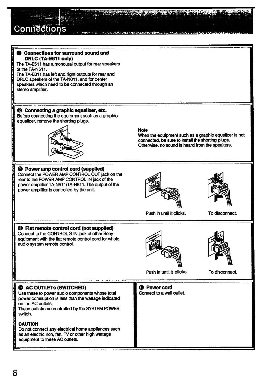
Connections.............
abaccbsout
sssansedseaeaaieed
dsoinascsasuassaceasdassnes
4
Connecting
audio
equipment...............000
sscdsdeteeicbaasvocese
4
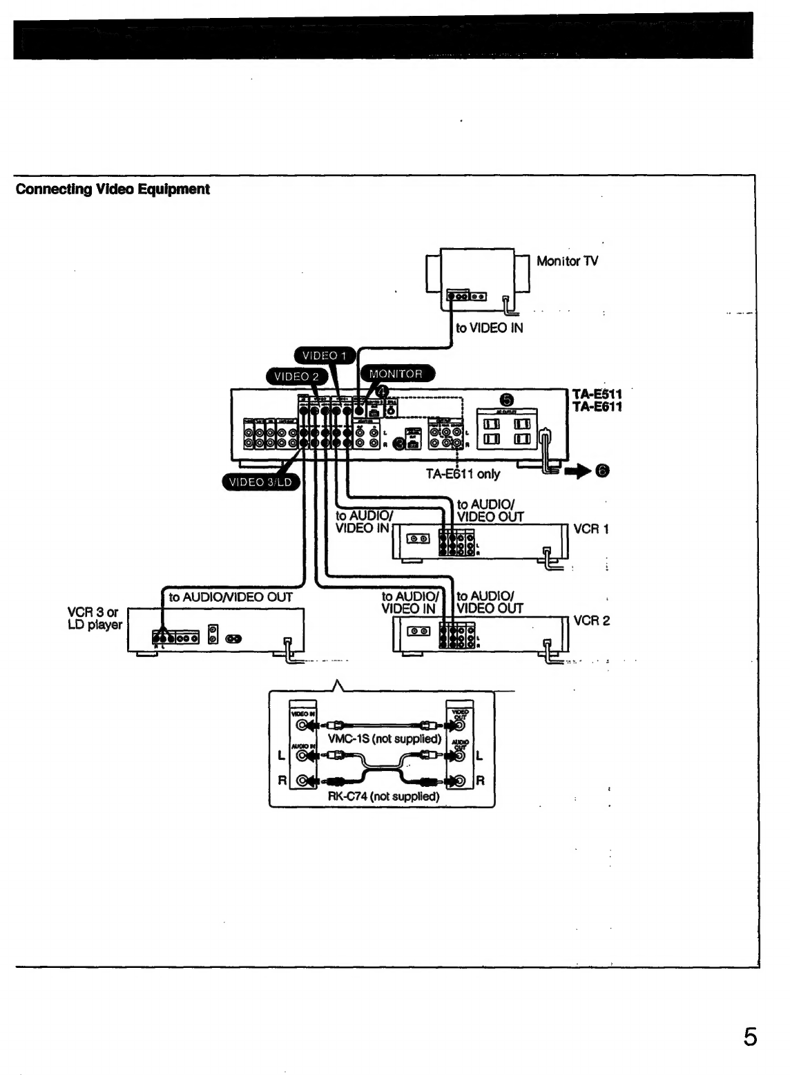
Connecting
video
equipmMent
............cscscssoscesessssorsrneseseees
5
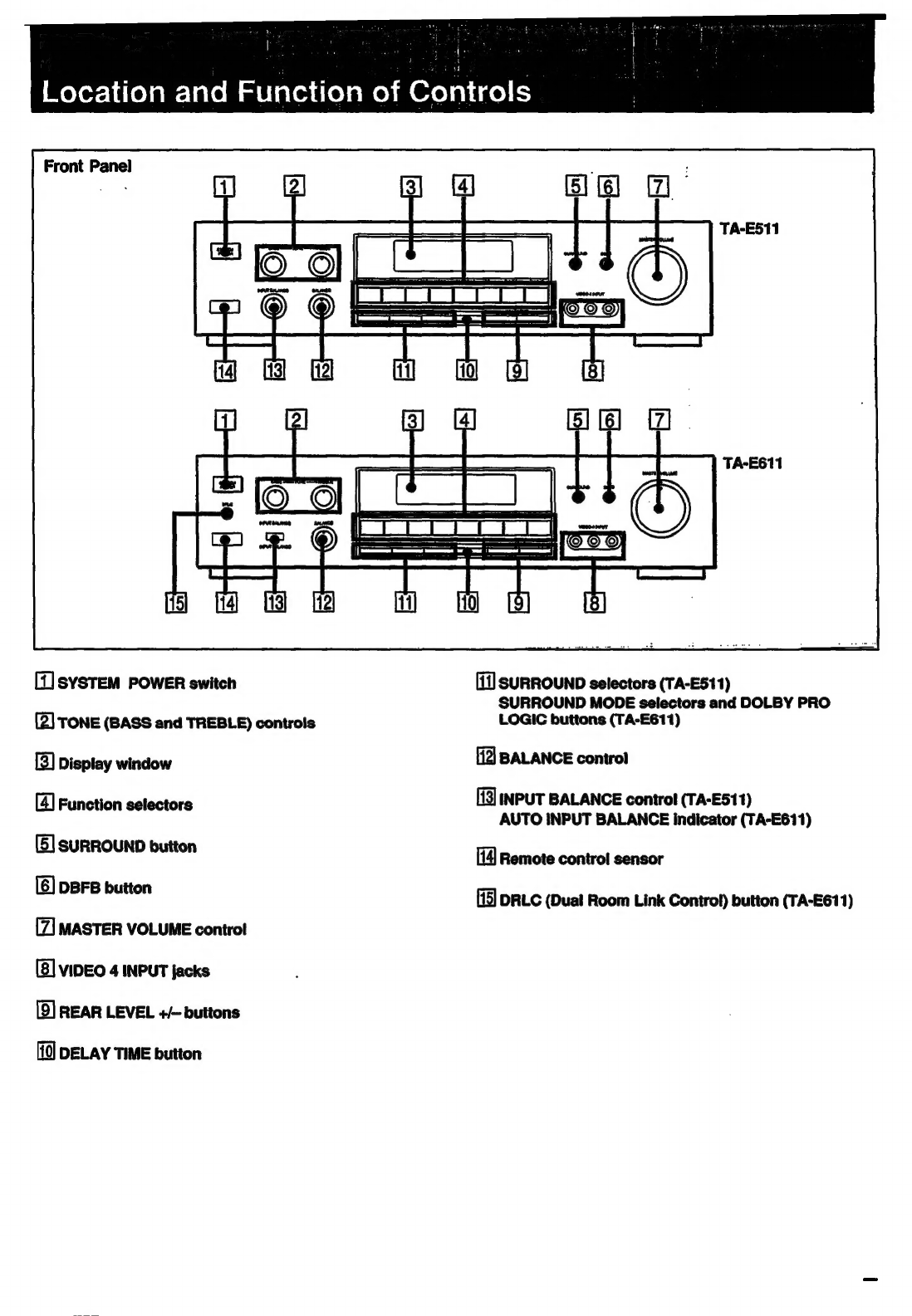
Location
and
function
of
controls
............
Sadeanddesdaveed
vecseee
7
FONE
PANE
cs.
scsssesscsssssocasassossisceotsoosenovesscenesooosessstbevevensessacs
7
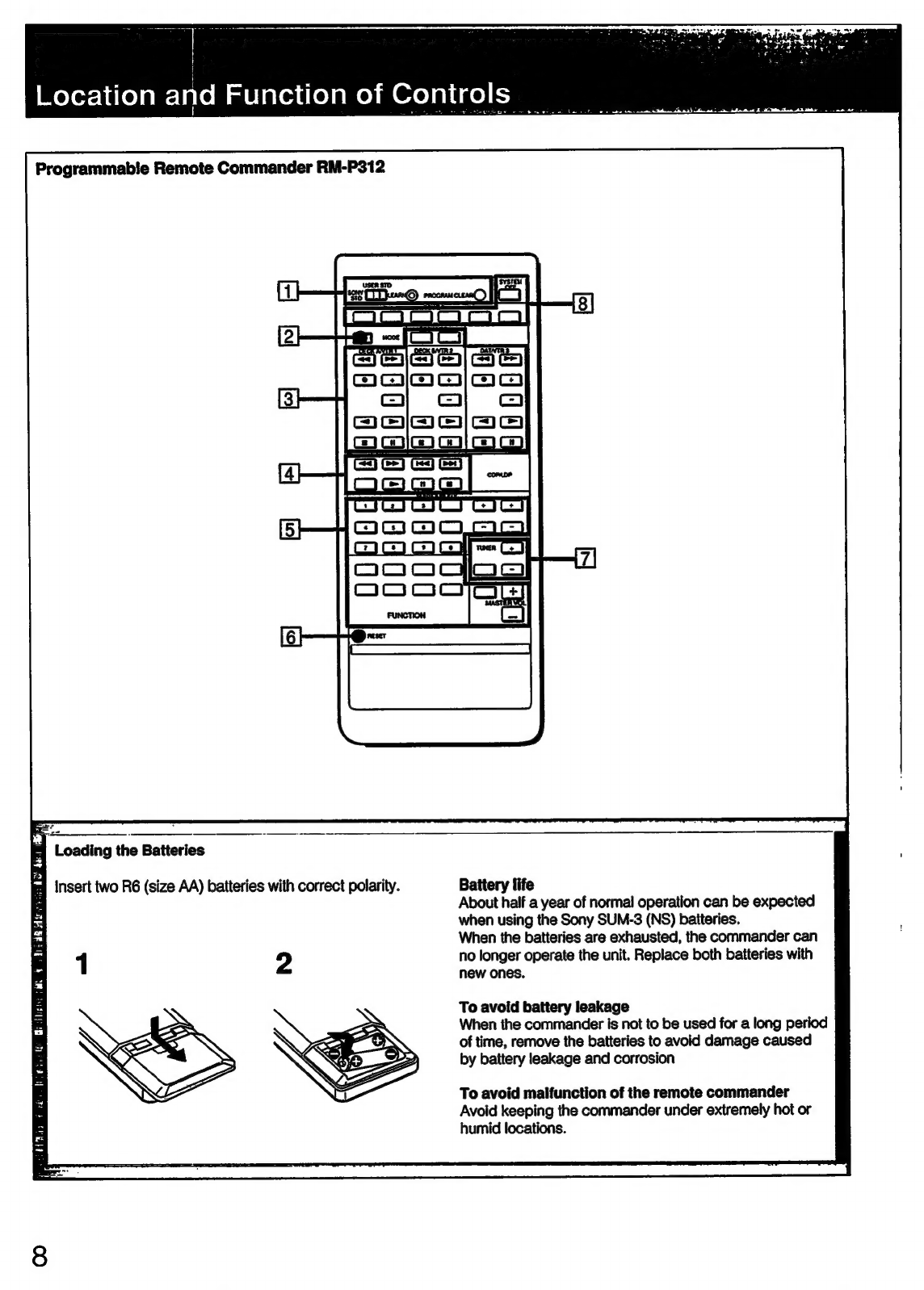
Programmable
remote
commander
RM-P312
........sccsscceee
8
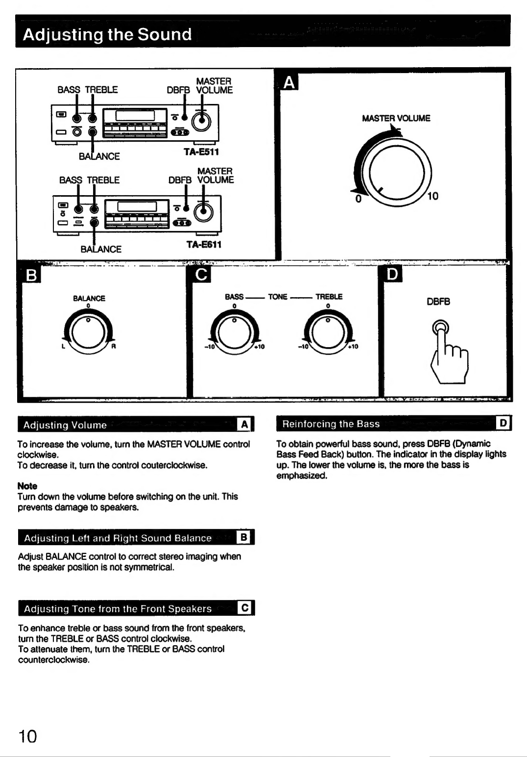
Adjusting
the
soumnd.....................ccsssssressssssssssesssesessvseees
10
Listening
to/watching
program
source
..............
aatecosetse
11
Basic
Operation
.......sssssssecesesesececssssesessecesersorsrserssseseoees
11
Combining
the
video
image
with
the
sound
from
another
Program
SOULCE
............cecssrsssssssssssaseeseees
12
Recording
audio
program
SOUICE
...............ccccccccscsesosseee
13
Recording
video
program
source
...........
iacdusescavaveesesesde
14
Editing
audio/video
program
sources
....................ss000
15
Getting
ready
to
enjoy
surround
sound
.................0000
16
Basic
Surround
SyStOMS..............ccsessssssssesessserssesosossecesees
16
Selecting
the
speaker
operation
mode
in
the
Dolby*
Pro
Logic
function
(TA-E611
only)...........
16
Adjusting
the
surround
level
and
input
balance
for
Dolby
Surround
SySteM
............scsscsescesessssscssesescesesees
17
Enjoying
the
surround
Sound
................cccccesccscscssceres
18
Listening
to
with
surround
eff6Ct
..........ccccccsesoressssesososees
18
Function
of
Dual
Room
Link
Control
system
(TA-E611
Oy)
...............csescscssececssersessesseeseseces
sersecessseseee
WD
Connections
for
Dual
Room
‘Link
Control
SYSTEM
........0006
19
Operations
............sccscsosssssrscssescrsceee
sexesdeseveSenees
Ssseaveeseausess
19
Using
the
remote
Commande’
................ccccssssssssscsssssveeee
20
Programming
signals
of
other
audio/video
equipment
with
RM-P312
..........0ccsserecssrsssessesssssrsvsenes
20
Controlling
equipment.........
sasdasdehssdeessssssedesnsvocecbest
Bahiocees
21
SPOCHICATIONS
0.0.0...
ecseeseceseessssessesesesssessessssssesecsesecsees
22
Troubleshooting
................sccccscssesececsssssssssrsecsssesesvsessees
23
*
Manufactured
under
license
from
Dolby
Laboratories
Licensing
Corporation.
Additionally
licensed
under
one
or
more
of
the
following
patents:
U.S.
numbers
3,632,886,
3,746,792
and
3,959,590;
Canadian
numbers
1,004,603
and
1,037,877.
“DOLBY”
and
the
double-D
symbol
DU
are
trademarks
of
Dolby
Laboratories
Licensing
Corporation.