2
Owner’s Record
The model and serial numbers are located on
the side. Record these numbers in the spaces
provided below.
Refer to these numbers whenever you call
upon your Sony dealer regarding this
product.
Model No. Serial No.
To reduce the risk of fire or electric
shock, do not expose this apparatus
to rain or moisture.
To avoid electrical shock, do not
open the cabinet. Refer servicing to
qualified personnel only.
WARNING
THIS APPARATUS MUST BE
EARTHED.
WARNING on power connection
Use a proper power cord for your local
power supply.
1. Use the approved Power Cord (3-core
mains lead)/Appliance Connector/Plug
with earthing-contacts that conforms to
the safety regulations of each country if
applicable.
2. Use the Power Cord (3-core mains lead)/
Appliance Connector/Plug conforming to
the proper ratings (Voltage, Ampere). If
you have questions on the use of the
above Power Cord/Appliance Connector/
Plug, please consult a qualified service
personnel.
For the customers in Europe
This product with the CE marking complies
with the EMC Directive issued by the
Commission of the European Community.
Compliance with this directive implies
conformity to the following European
standards:
• EN55103-1: Electromagnetic Interference
(Emission)
• EN55103-2: Electromagnetic
Susceptibility (Immunity)
This product is intended for use in the
following Electromagnetic Environments:
E1 (residential), E2 (commercial and light
industrial), E3 (urban outdoors), E4
(controlled EMC environment, ex. TV
studio).
For the customers in Europe
The manufacturer of this product is Sony
Corporation, 1-7-1 Konan, Minato-ku,
Tokyo, Japan.
The Authorized Representative for EMC,
medical devices, and product safety is Sony
Deutschland GmbH, Hedelfinger Strasse 61,
70327 Stuttgart, Germany; TEL: (0)711
5858 0; FAX: (0)711 5858 235.
For any service or guarantee matters please
refer to the addresses given in separate
service or guarantee documents.
Important safeguards/notices for use
in the medical environments
1. All the equipments connected to this unit
shall be certified according to Standard
IEC60601-1, IEC60950-1, IEC60065 or
other IEC/ISO Standards applicable to
the equipments.
2. Furthermore all configurations shall
comply with the system standard
IEC60601-1-1. Everybody who connects
additional equipment to the signal input
part or signal output part configures a
medical system, and is therefore,
responsible that the system complies with
the requirements of the system standard
IEC60601-1-1. If in doubt, consult the
qualified service personnel.
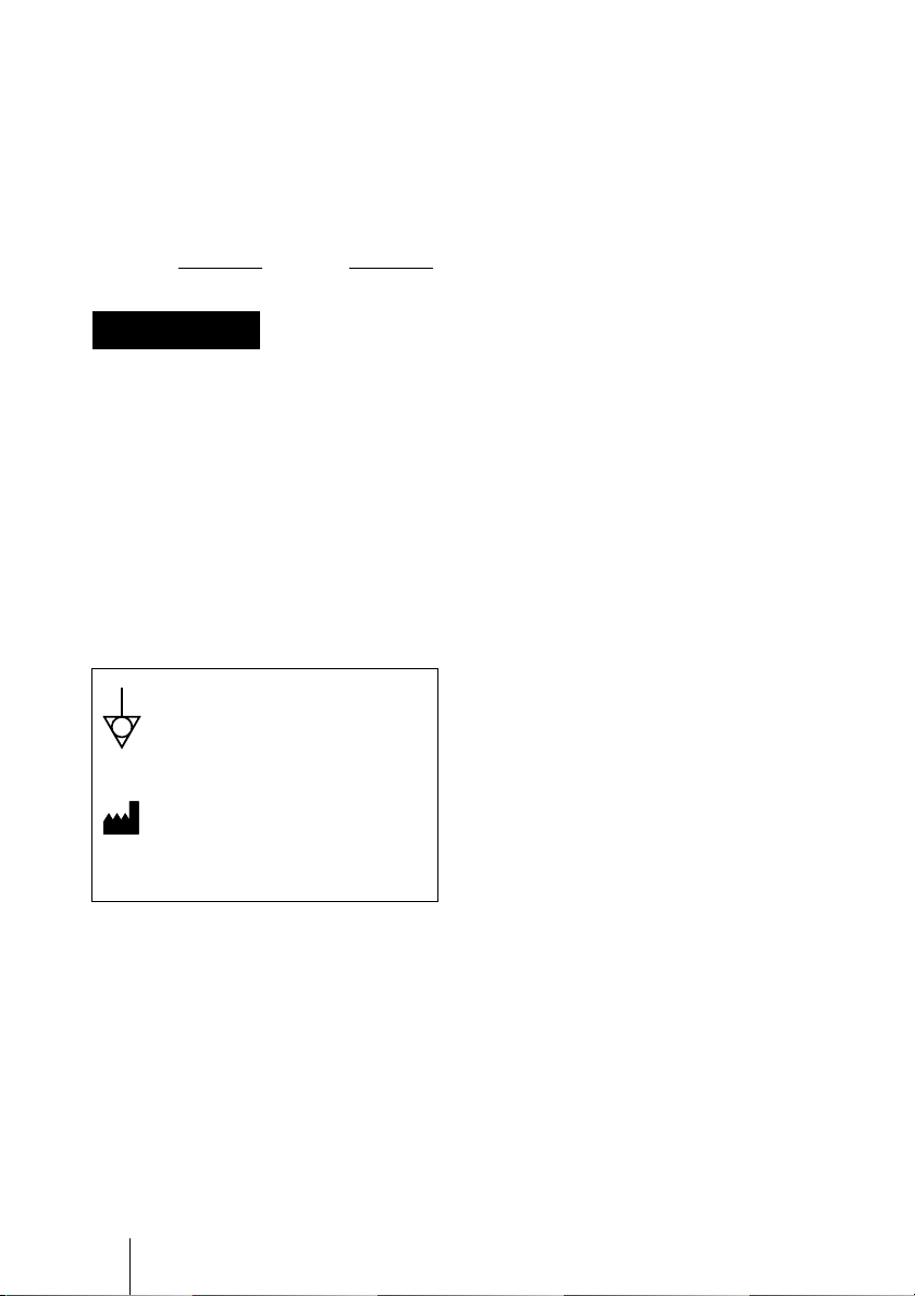
WARNING
This symbol indicates the
equipotential terminal which
brings the various parts of a system
to the same potential.
This symbol indicates the
manufacturer, and appears next to
the manufacturer’s name and
address.