99
MEX-DV1000/DV2000
(DV1000: AEP, UK and Russian models)
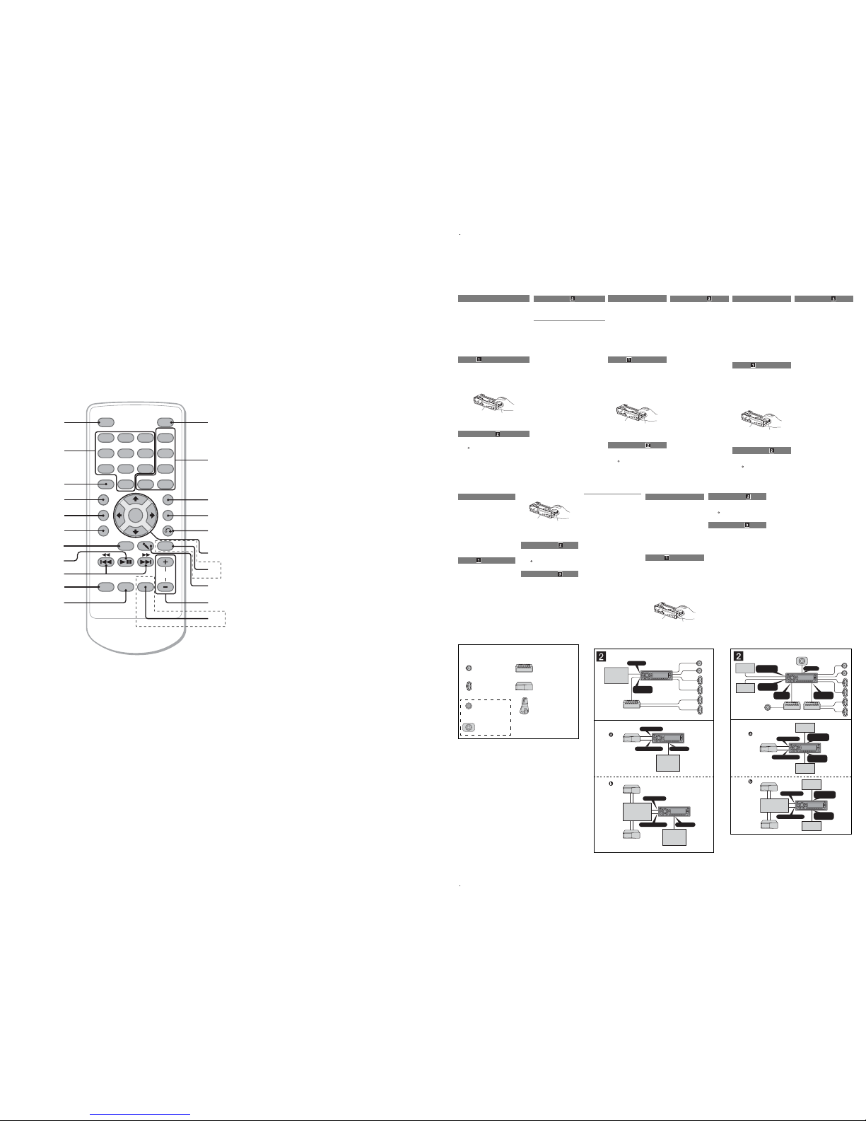
Card remote commander
RM-X161 (DV2000: US and Canadian models)
RM-X162 (DV2000: Russian model)
RM-X163 (DV2000: E, Indian and Chinese models)
RM-X166 (DV1000: AEP, UK and Russian models)
RM-X167 (DV1000: E, Indian and Chinese models)
Refer to the pages listed for details.
Remove the insulation film before use.
AOFF button
To power off/stop the source (press); shut
off completely (press and hold).
BNumber buttons
Disc:
To locate a title/chapter/track.
Radio:
To receive stored stations (press); store
stations (press and hold).
CCLEAR button
To delete an entered number.
DSYSTEM SETUP button
To open the system setup menu.
ELIST/CAT*
1
button
T
(US and Canadian models)
(AEP, UK and Russian models)
o list up.*
2
FSOUND button
To open the sound menu.
ZXZ
OFF ATT
AUDIO
SUBTITLE
ANGLE
MENUCLEAR
SYSTEM SETUP
LIST/PTY
SOUND
PICTURE
VISUAL SETUP
DSPL
TOP MENU
1
0
23
VOL
EQ
445566
778899
SRC
MODE
ENTER
PLII
AF/TA
qs1
2
3
4
5
6
7
8
9
0
qa w;
qd
qf
qg
qj
qh
ql
wa
qk
(AEP, UK and Russian models)
(DV2000)
LIST/PTY (Program Type) button
To list up*
2
; select PTY in RDS.
(E, Indian and Chinese models)
LIST button
To list up*
2
GPICTURE EQ button
To select the picture quality.
Hu(Play/Pause) button
To start/pause playback.
I.m/M> buttons
Disc:
To skip a chapter/track/scene (press);
reverse/fast-forward disc (press and hold
momentarily); reverse/fast-forward track
(press and hold).*
3
Radio:
To tune in stations automatically (press); find
a station manually (press and hold).
JSRC (Source) button
To power on; change the source (Radio/Disc/
AUX/SAT*
1
).
KMODE button
To select the radio band (FM/AM); select the
SAT tuner band (mode)*
1
; select the unit*
4
.
LATT (Attenuate) button
To attenuate the sound
(to cancel, press again).
MDVD playback setting buttons
(AUDIO):
To change the audio language/format.
(For VCD/CD/MP3/WMA, to change the
audio channel.)
(SUBTITLE):
To change the subtitle language.
(ANGLE):
To change the viewing angle.
(TOP MENU):
To open the top menu on a DVD.
(MENU):
To open the menu on a disc.
NVISUAL SETUP button
To open the play mode/visual setup menu.
ODSPL (Display) button
To change display items.
PO(Return) button
To return to the previous display; return to
the menu on a VCD*
5
.
Q</M/m/,(Cursor)/ENTER buttons
To move the cursor and apply a setting.
RPLII (Pro Logic II) button
To select a Dolby Pro Logic II mode.
(DV2000)
Sm(Microphone) button
To activate the karaoke mode.
TVOL (Volume) +/– buttons
To adjust the volume.
*1
When the SAT tuner is connected.
*2
When a Super Audio CD/CD/MP3/WMA/JPEG/
Divx is played.
(Divx is except US and Canadian models)
*3
Operation differs depending on the disc.
*4
When a CD changer is connected.
*5
When playing with PBC function.
Note
If the unit is turned off and the display disappears, it
cannot be operated with the card remote commander
unless
(SOURCE)
on the main unit is pressed, or a
disc is inserted to activate the unit first.
Tip
For details on how to replace the battery, see
“Replacing the lithium battery of the card remote
commander”.
UAF (Alternative Frequencies)/TA
(Traffic Announcement) button
T
(AEP, UK and Russian models)
o set AF and TA in RDS.
Cautions
− This unit is designed for negative ground (earth) 12 V DC operation
only.
− Do not get the leads under a screw, or caught in moving parts (e.g.
seat railing).
− Before making connections, turn the car ignition off to avoid short
circuits.
− Connect the power supply lead ʕto the unit and speakers before
connecting it to the auxiliary power connector.
−Run all ground (earth) leads to a common ground (earth)
point.
− Be sure to insulate any loose unconnected leads with electrical tape
for safety.
Notes on the power supply lead (yellow)
− When connecting this unit in combination with other stereo
components, the connected car circuitís rating must be higher than
the sum of each componentís fuse.
− When no car circuits are rated high enough, connect the unit directly
to the battery.
Parts list
− The numbers in the list are keyed to those in the instructions.
− The bracket ʓand the protection collar ʗare attached to the unit
before shipping. Before mounting the unit, use the release keys ʖto
remove the bracket ʓand the protection collar ʗfrom the unit. For
details, see ìRemoving the protection collar and the bracket (ǹ)î on
the reverse side of the sheet.
−Keep the release keys ʖfor future use as they are also
necessary if you remove the unit from your car.
Caution
Handle the bracket ʓcarefully to avoid injuring your Ýngers.
Note
Before installing, make sure that the catches on both sides of the bracketʓare
bent inwards 2 mm (
3
/
32
in). If the catches are straight or bent outwards, the unit
will not be installed securely and may spring out.
Connection example
Notes (ǵ-A)
•Be sure to connect the ground (earth) lead before connecting the amplifier.
•The alarm will only sound if the built-in amplifier is used.
Tip (ǵ-B-)
For connecting two or more CD changers, the source selector XA-C40 (not
supplied) is necessary.
ʓCatch
Connection diagram
ɞTo a metal surface of the car
First connect the black ground (earth) lead, then connect the
yellow and red power supply leads.
ɟTo the power antenna (aerial) control lead or
power supply lead of antenna (aerial) booster
Notes
•It is not necessary to connect this lead if there is no power
antenna (aerial) or antenna (aerial) booster, or with a
manually-operated telescopic antenna (aerial).
•When your car has a built-in FM/AM antenna (aerial) in the
rear/side glass, see “Notes on the control and power supply
leads.”
ɠTo AMP REMOTE IN of an optional power
amplifier
This connection is only for amplifiers.Connecting any other
system may damage the unit.
ɡTo the +12 V power terminal which is
energized in the accessory position of the
ignition switch
Notes
•If there is no accessory position, connect to the +12 V
power (battery) terminal which is energized at all times.
Be sure to connect the black ground (earth) lead to a metal
surface of the car first.
•When your car has a built-in FM/AM antenna (aerial) in the
rear/side glass, see “Notes on the control and power supply
leads.”
ɢTo the +12 V power terminal which is
energized at all times
Be sure to connect the black ground (earth) lead to a metal
surface of the car first.
ɣTo the parking brake switch cord
ɤTo the microphone (not supplied)
Notes on the control and power supply leads
•The power antenna (aerial) control lead (blue) supplies +12 V
DC when you turn on the tuner.
•When your car has built-in FM/AM antenna (aerial) in the
rear/side glass, connect the power antenna (aerial) control lead
(blue) or the accessory power supply lead (red) to the power
terminal of the existing antenna (aerial) booster.For details,
consult your dealer.
•A power antenna (aerial) without a relay box cannot be used
with this unit.
Memory hold connection
When the yellow power supply lead is connected, power will
always be supplied to the memory circuit even when the ignition
switch is turned off.
Notes on speaker connection
•Before connecting the speakers, turn the unit off.
•Use speakers with an impedance of 4 to 8 ohms, and with
adequate power handling capacities to avoid its damage.
•Do not connect the speaker terminals to the car chassis, or
connect the terminals of the right speakers with those of the left
speaker.
•Do not connect the ground (earth) lead of this unit to the
negative (–) terminal of the speaker.
•Do not attempt to connect the speakers in parallel.
•Connect only passive speakers.Connecting active speakers
(with built-in amplifiers) to the speaker terminals may damage
the unit.
•To avoid a malfunction, do not use the built-in speaker leads
installed in your car if the unit shares a common negative (–)
lead for the right and left speakers.
•Do not connect the unit’s speaker leads to each other.
Notes on connection
•If speaker and amplifier are not connected correctly,“FAILURE”
appears in the display.In this case, make sure the speaker and
amplifier are connected correctly.
•If you are to use the monitor for the rear seats, connect the
parking brake switch cord to the ground (earth).
Cautions
− This unit is designed for negative ground (earth) 12 V
DC operation only.
− Do not get the leads under a screw, or caught in moving
parts (e.g. seat railing).
− Before making connections, turn the car ignition off to
avoid short circuits.
− Connect the yellow and red power supply leads only
after all other leads have been connected.
−Run all ground (earth) leads to a common
ground (earth) point.
− Be sure to insulate any loose unconnected leads with
electrical tape for safety.
Notes on the power supply lead (yellow)
− When connecting this unit in combination with other
stereo components, the connected car circuitís rating
must be higher than the sum of each componentís fuse.
− When no car circuits are rated high enough, connect
the unit directly to the battery.
Parts list
− The numbers in the list are keyed to those in the
instructions.
− The bracket ʓand the protection collar ʖare
attached to the unit before shipping. Before mounting
the unit, use the release keys ʕto remove the bracket
ʓand the protection collar ʖfrom the unit. For
details, see ìRemoving the protection collar and the
bracket (ǹ)î on the reverse side of the sheet.
−Keep the release keys ʕfor future use as they
are also necessary if you remove the unit from
your car.
Caution
Handle the bracket ʓcarefully to avoid injuring your
Ýngers.
Note
Before installing, make sure that the catches on both sides of
the bracket ʓare bent inwards 2 mm (3/32 in).If the catches are
straight or bent outwards, the unit will not be installed securely
and may spring out.
Connection example
Notes (ǵ-A)
•Be sure to connect the ground (earth) lead before connecting
the amplifier.
•The alarm will only sound if the built-in amplifier is used.
Tip (ǵ-B-)
For connecting two or more CD changers, the source selector
XA-C40 (not supplied) is necessary.
Catch
ʓ
(DV1000: E,Indian and Chinese models)
Cautions
− This unit is designed for negative ground (earth) 12 V
DC operation only.
− Do not get the leads under a screw, or caught in moving
parts (e.g. seat railing).
− Before making connections, turn the car ignition off to
avoid short circuits.
− Connect the yellow and red power supply leads only
after all other leads have been connected.
−Run all ground (earth) leads to a common
ground (earth) point.
− Be sure to insulate any loose unconnected leads with
electrical tape for safety.
− The use of optical instruments with this product will
increase eye hazard.
Notes on the power supply lead (yellow)
− When connecting this unit in combination with other
stereo components, the connected car circuitís rating
must be higher than the sum of each componentís fuse.
− When no car circuits are rated high enough, connect the
unit directly to the battery.
Parts list
− The numbers in the list are keyed to those in the
instructions.
− The bracket ʓand the protection collar ʗare attached
to the unit before shipping. Before mounting the unit,
use the release keys ʖto remove the bracket ʓand
the protection collar ʗfrom the unit. For details, see
ìRemoving the protection collar and the bracket ( ǹ)î
on the reverse side of the sheet.
−Keep the release keys ʖfor future use as they
are also necessary if you remove the unit from
your car.
Caution
Handle the bracket ʓcarefully to avoid injuring your
Ýngers.
Note
Before installing, make sure that the catches on both sides of
the bracket ʓare bent inwards 2 mm (
3
/
32
in). If the catches are
straight or bent outwards, the unit will not be installed securely
and may spring out.
Connection example
Notes (ǵ-A)
•Be sure to connect the ground (earth) lead before connecting
the amplifier.
•The alarm will only sound if the built-in amplifier is used.
Tip (ǵ-B-)
For connecting two or more CD changers, the source selector
XA-C40 (not supplied) is necessary.
Connection diagram
ɞTo a metal surface of the car
First connect the black ground (earth) lead, then connect the
yellow and red power supply leads.
ɟTo the power antenna (aerial) control lead or
power supply lead of antenna (aerial) booster
Notes
•It is not necessary to connect this lead if there is no power
antenna (aerial) or antenna (aerial) booster, or with a
manually-operated telescopic antenna (aerial).
•When your car has a built-in FM/AM antenna (aerial) in the
rear/side glass, see “Notes on the control and power supply
leads.”
ɠTo AMP REMOTE IN of an optional power
amplifier
This connection is only for amplifiers.Connecting any other
system may damage the unit.
ɡTo the interface cable of a car telephone
ɢTo a car’s illumination signal
Be sure to connect the black ground (earth) lead to a metal
surface of the car first.
ɣTo the +12 V power terminal which is
energized in the accessory position of the
ignition switch
Notes
•If there is no accessory position, connect to the +12 V
power (battery) terminal which is energized at all times.
Be sure to connect the black ground (earth) lead to a metal
surface of the car first.
•When your car has a built-in FM/AM antenna (aerial) in the
rear/side glass, see “Notes on the control and power supply
leads.”
ɤTo the +12 V power terminal which is
energized at all times
Be sure to connect the black ground (earth) lead to a metal
surface of the car first.
ɥTo the parking brake switch cord
ɦTo the microphone (not supplied)
Notes on the control and power supply leads
•The power antenna (aerial) control lead (blue) supplies +12 V
DC when you turn on the tuner.
•When your car has built-in FM/AM antenna (aerial) in the
rear/side glass, connect the power antenna (aerial) control lead
(blue) or the accessory power supply lead (red) to the power
terminal of the existing antenna (aerial) booster. Fordetails,
consult your dealer.
•A power antenna (aerial) without a relay box cannot be used
with this unit.
Memory hold connection
When the yellow power supply lead is connected, power will
always be supplied to the memory circuit even when the ignition
switch is turned off.
Notes on speaker connection
•Before connecting the speakers, turn the unit off.
•Use speakers with an impedance of 4 to 8 ohms, and with
adequate power handling capacities to avoid its damage.
•Do not connect the speaker terminals to the car chassis, or
connect the terminals of the right speakers with those of the left
speaker.
•Do not connect the ground (earth) lead of this unit to the
negative (–) terminal of the speaker.
•Do not attempt to connect the speakers in parallel.
•Connect only passive speakers.Connecting active speakers
(with built-in amplifiers) to the speaker terminals may damage
the unit.
•To avoid a malfunction, do not use the built-in speaker leads
installed in your car if the unit shares a common negative (–)
lead for the right and left speakers.
•Do not connect the unit’s speaker leads to each other.
Notes on connection
•If speaker and amplifier are not connected correctly,“FAILURE”
appears in the display.In this case, make sure the speaker and
amplifier are connected correctly.
•If you are to use the monitor for the rear seats, connect the
parking brake switch cord to the ground (earth).
Catch
ʓ
(DV2000: US and Canadian models)
Equipment used in illustrations (not supplied)
Appareils utilisés dans les illustrations (non fournis)
Equipo utilizado en las ilustraciones (no suministrado)
Rear speaker
Haut-parleur arrière
Altavoz posterior
Front speaker
Haut-parleur avant
Altavoz frontal
Active subwoofer
Caisson de graves actif
Altavoz potenciador de
graves activo
Power amplifier
Amplificateur de puissance
Amplificador de potencia
CD changer
Changeur CD
Cambiador de CD
Rotary commander RM-X4S
Satellite de commande RM-X4S
Mando rotatorio RM-X4S
Center speaker
Haut-parleur central
Altavoz central
REAR
AUDIO OUT
VIDEO OUT
BUS AUDIO IN
BUS CONTROL IN VIDEO OUT
BUS AUDIO IN
BUS CONTROL IN VIDEO OUT
A
B
*not supplied
nicht mitgeliefert
non fourni
non in dotazione
niet bijgeleverd
Source selector*
Signalquellenwähler*
Sélecteur de source*
Selettore di fonte*
Bronkeuzeschakelaar*
XA-C40
Monitor*
Monitor*
Moniteur
*
Monitor*
Monitor*
Monitor*
Monitor*
Moniteur
*
Monitor*
Monitor*
Monitor*
Monitor*
Moniteur
*
Monitor*
Monitor*
*not supplied
nicht mitgeliefert
non fourni
non in dotazione
niet bijgeleverd
*not supplied
nicht mitgeliefert
non fourni
non in dotazione
niet bijgeleverd
A
B
REARVIDEO
OUT
REAR AUDIO
OUT
SUB OUT
CENTER
OUT
FRONTVIDEO
OUT
FRONTVIDEO
OUT
BUS AUDIO IN
BUS CONTROL IN REAR VIDEO
OUT
BUS AUDIO IN
BUS CONTROL IN REAR VIDEO
OUT
FRONTVIDEO
OUT
Source selector*
Sélecteur de source*
Selector de fuente*
XA-C40
*not supplied
non fourni
no suministrado
Monitor*
Moniteur*
Monitor*
Monitor*
Moniteur*
Monitor*
Monitor*
Moniteur*
Monitor*
Monitor*
Moniteur*
Monitor*
Monitor*
Moniteur*
Monitor*
Monitor*
Moniteur*
Monitor*
*not supplied
non fourni
no suministrado
*not supplied
non fourni
no suministrado
Cautions
− This unit is designed for negative ground (earth) 12 V
DC operation only.
− Do not get the leads under a screw, or caught in moving
parts (e.g. seat railing).
− Before making connections, turn the car ignition off to
avoid short circuits.
− Connect the power supply lead ʖto the unit and
speakers before connecting it to the auxiliary power
connector.
−Run all ground (earth) leads to a common
ground (earth) point.
− Be sure to insulate any loose unconnected leads with
electrical tape for safety.
Notes on the power supply lead (yellow)
− When connecting this unit in combination with other
stereo components, the connected car circuitís rating
must be higher than the sum of each componentís fuse.
− When no car circuits are rated high enough, connect
the unit directly to the battery.
Parts list
− The numbers in the list are keyed to those in the
instructions.
− The bracket ʓand the protection collar ʘare
attached to the unit before shipping. Before mounting
the unit, use the release keys ʗto remove the bracket
ʓand the protection collar ʘfrom the unit. For
details, see ìRemoving the protection collar and the
bracket (ǹ)î on the reverse side of the sheet.
−Keep the release keys ʗfor future use as they
are also necessary if you remove the unit from
your car.
Caution
Handle the bracket ʓcarefully to avoid injuring your
Ýngers.
Catch
ʓ
Note
Before installing, make sure that the catches on both sides of
the bracket ʓare bent inwards 2 mm.If the catches are straight
or bent outwards, the unit will not be installed securely and may
spring out.
Connection example
Notes (ǵ-A)
•Be sure to connect the ground (earth) lead before connecting
the amplifier.
•The alarm will only sound if the built-in amplifier is used.
Tip (ǵ-B-)
For connecting two or more CD changers, the source selector
XA-C40 (not supplied) is necessary.
Connection diagram
ɸTo AMP REMOTE IN of an optional power
amplifier
This connection is only for amplifiers.Connecting any other
system may damage the unit.
ɹTo the interface cable of a car telephone
ɺTo the parking brake switch cord
ɻTo the microphone (not supplied)
Cautions
− This unit is designed for negative ground (earth) 12 V
DC operation only.
− Do not get the leads under a screw, or caught in moving
parts (e.g. seat railing).
− Before making connections, turn the car ignition off to
avoid short circuits.
− Connect the yellow and red power supply leads only
after all other leads have been connected.
−Run all ground (earth) leads to a common
ground (earth) point.
− Be sure to insulate any loose unconnected leads with
electrical tape for safety.
Notes on the power supply lead (yellow)
− When connecting this unit in combination with other
stereo components, the connected car circuitís rating
must be higher than the sum of each componentís fuse.
− When no car circuits are rated high enough, connect
the unit directly to the battery.
Parts list
− The numbers in the list are keyed to those in the
instructions.
− The bracket ʓand the protection collar ʗare
attached to the unit before shipping. Before mounting
the unit, use the release keys ʖto remove the bracket
ʓand the protection collar ʗfrom the unit. For
details, see ìRemoving the protection collar and the
bracket (ǹ)î on the reverse side of the sheet.
−Keep the release keys ʖfor future use as they
are also necessary if you remove the unit from
your car.
Caution
Handle the bracket ʓcarefully to avoid injuring your
Ýngers.
Note
Before installing, make sure that the catches on both sides of
the bracket ʓare bent inwards 2 mm (
3
/
32
in). If the catches are
straight or bent outwards, the unit will not be installed securely
and may spring out.
Catch
ʓ
(DV2000: E,Indian and Chinese models)
Connection diagram
ɸTo AMP REMOTE IN of an optional power amplifier
This connection is only for amplifiers.Connecting any other system may
damage the unit.
ɹTo the parking brake switch cord
ɺTo the microphone (not supplied)
Warning
If you have a power antenna (aerial) without a relay box, connecting
this unit with the supplied power supply lead ʕmay damage the
antenna (aerial).
Notes on the control and power suppy leads
•The power antenna (aerial) control lead (blue) supplies +12 V DC when you
turn on the tuner, or when you activate the AF (Alternative Frequency)or TA
(TrafficAnnouncement) function.
•When your car has built-in FM/MW/LWantenna (aer ial) in the rear/side glass,
connect the power antenna (aerial) control lead (blue) or the accessory power
supply lead (red) to the power terminal of the existing antenna (aerial) booster.
For details, consult your dealer.
•A power antenna (aerial) without a relay box cannot be used with this unit.
Memory hold connection
When the yellow power supply lead is connected, power will alwaysbe supplied
to the memory circuit even when the ignition switch is turned off.
Notes on speaker connection
•Before connecting the speakers, turn the unit off.
•Use speakers with an impedance of 4 to 8 ohms, and with adequate power
handling capacities to avoid its damage.
•Do not connect the speaker terminals to the car chassis, or connect the
terminals of the right speakers with those of the left speaker.
•Do not connect the ground (earth) lead of this unit to the negative (–) terminal
of the speaker.
•Do not attempt to connect the speakers in parallel.
•Connect only passive speakers.Connecting active speakers (with built-in
amplifiers) to the speaker terminals may damage the unit.
•To avoid a malfunction, do not use the built-in speaker leads installed in
your car if the unit shares a common negative (–) lead for the right and left
speakers.
•Do not connect the unit’s speaker leads to each other.
Notes on connection
•If speaker and amplifier are not connected correctly,“FAILURE” appears in
the display.In this case, make sure the speaker and amplifier are connected
correctly.
•If you are to use the monitor for the rear seats, connect the parking brake
switch cord to the ground (earth).
Warning
If you have a power antenna (aerial) without a relay box,
connecting this unit with the supplied power supply lead
ʖmay damage the antenna (aerial).
Notes on the control and power supply leads
•The power antenna (aerial) control lead (blue) supplies +12 V
DC when you turn on the tuner, or when you activate the AF
(Alternative Frequency) or TA (Traffic Announcement) function.
•When your car has built-in FM/MW/LWantenna (aer ial) in the
rear/side glass, connect the power antenna (aerial) control
lead (blue) or the accessory power supply lead (red) to the
power terminal of the existing antenna (aerial) booster.For
details, consult your dealer.
•A power antenna (aerial) without a relay box cannot be used
with this unit.
Memory hold connection
When the yellow power input lead is connected, power will
always be supplied to the memory circuit even when the ignition
switch is turned off.
Notes on speaker connection
•Before connecting the speakers, turn the unit off.
•Use speakers with an impedance of 4 to 8 ohms, and with
adequate power handling capacities to avoid its damage.
•Do not connect the speaker terminals to the car chassis, or
connect the terminals of the right speakers with those of the
left speaker.
•Do not connect the ground (earth) lead of this unit to the
negative (–) terminal of the speaker.
•Do not attempt to connect the speakers in parallel.
•Connect only passive speakers.Connecting active speakers
(with built-in amplifiers) to the speaker terminals may damage
the unit.
•To avoid a malfunction, do not use the built-in speaker leads
installed in your car if the unit shares a common negative (–)
lead for the right and left speakers.
•Do not connect the unit’s speaker leads to each other.
Notes on connection
•If speaker and amplifier are not connected correctly,“FAILURE”
appears in the display.In this case, make sure the speaker and
amplifier are connected correctly.
•If you are to use the monitor for the rear seats, connect the
parking brake switch cord to the ground (earth).
Connection example
Notes (ǵ-A)
•Be sure to connect the ground (earth) lead before connecting
the amplifier.
•The alarm will only sound if the built-in amplifier is used.
Tip (ǵ-B-)
For connecting two or more CD changers, the source selector
XA-C40 (not supplied) is necessary.
ɦp( pp)
Notes on the control and power supply leads
•The power antenna (aerial) control lead (blue) supplies +12 V
DC when you turn on the tuner.
•When your car has built-in FM/AM antenna (aerial) in the
rear/side glass, connect the power antenna (aerial) control lead
(blue) or the accessory power supply lead (red) to the power
terminal of the existing antenna (aerial) booster.For details,
consult your dealer.
•A power antenna (aerial) without a relay box cannot be used
with this unit.
Memory hold connection
When the yellow power supply lead is connected, power will
always be supplied to the memory circuit even when the ignition
switch is turned off.
Notes on speaker connection
•Before connecting the speakers, turn the unit off.
•Use speakers with an impedance of 4 to 8 ohms, and with
adequate power handling capacities to avoid its damage.
•Do not connect the speaker terminals to the car chassis, or
connect the terminals of the right speakers with those of the left
speaker.
•Do not connect the ground (earth) lead of this unit to the
negative (–) terminal of the speaker.
•Do not attempt to connect the speakers in parallel.
•Connect only passive speakers.Connecting active speakers
(with built-in amplifiers) to the speaker terminals may damage
the unit.
•To avoid a malfunction, do not use the built-in speaker leads
installed in your car if the unit shares a common negative (–)
lead for the right and left speakers.
•Do not connect the unit’s speaker leads to each other.
Notes on connection
•If speaker and amplifier are not connected correctly,“FAILURE”
appears in the display.In this case, make sure the speaker and
amplifier are connected correctly.
•If you are to use the monitor for the rear seats, connect the
parking brake switch cord to the ground (earth).
Connection diagram
ɞTo a metal surface of the car
First connect the black ground (earth) lead, then connect the
yellow and red power supply leads.
ɟTo the power antenna (aerial) control lead or
power supply lead of antenna (aerial) booster
Notes
•It is not necessary to connect this lead if there is no power
antenna (aerial) or antenna (aerial) booster, or with a
manually-operated telescopic antenna (aerial).
•When your car has a built-in FM/AM antenna (aerial) in the
rear/side glass, see “Notes on the control and power supply
leads.”
ɠTo AMP REMOTE IN of an optional power
amplifier
This connection is only for amplifiers.Connecting any other
system may damage the unit.
ɡTo the interface cable of a car telephone
ɢTo a car’s illumination signal
Be sure to connect the black ground (earth) lead to a metal
surface of the car first.
ɣTo the +12 V power terminal which is
energized in the accessory position of the
ignition switch
Notes
•If there is no accessory position, connect to the +12 V
power (battery) terminal which is energized at all times.
Be sure to connect the black ground (earth) lead to a metal
surface of the car first.
•When your car has a built-in FM/AM antenna (aerial) in the
rear/side glass, see “Notes on the control and power supply
leads.”
ɤTo the +12 V power terminal which is
energized at all times
Be sure to connect the black ground (earth) lead to a metal
surface of the car first.
ɥTo the parking brake switch cord
ɦTo the microphone (not supplied)
 User manual")


 User manual")