manuals.online logo
Brands
  1. Home
  2. •
  3. Brands
  4. •
  5. Sony
  6. •
  7. Car Stereo System
  8. •
  9. Sony XR-CA440X Product guide

Sony XR-CA440X Product guide

Sony Corporation © 2002 Printed in Thailand
XR-CA440X
3-238-899-11 (1)
Equipment used in illustrations (not supplied)
Аппаратура, фигурирующая в иллюстрациях (не прилагается)
Cautions
•This unit is designed for negative earth 12 V
DC operation only.
•Do not get the wires under a screw, or caught
in moving parts (e.g. seat railing).
•Before making connections, turn the car
ignition off to avoid short circuits.
•Connect the yellow and red power input leads
only after all other leads have been connected.
•Run all earth wires to a common earth
point.
•Be sure to insulate any loose unconnected
wires with electrical tape for safety.
Notes on the power supply cord (yellow)
•When connecting this unit in combination with
other stereo components, the connected car
circuit’s rating must be higher than the sum of
each component’s fuse.
•When no car circuits are rated high enough,
connect the unit directly to the battery.
Parts Iist (1)
The numbers in the list are keyed to those in the
instructions.
Caution
Handle the bracket 1carefully to avoid injuring
your fingers.
1
2
B
12
×4
3
46
×2
Power amplifier
Усилитель
CD/MD changer
Проигрыватель CD/ D
Front speaker
Передний громкоговоритель
Rear speaker
Задний громкоговоритель
BUS AUDIO IN
BUS CONTROL IN
AUDIO OUT REAR
BUS CONTROL IN
BUS AUDIO IN
A
Installation/Connections
Установка/Подсоединение
FM/AM Cassette
Car Stereo
Connection example (2)
Notes (2-A)
• Be sure to connect the earth cord before
connecting the amplifier.
• If you connect an optional power amplifier and do
not use the built-in amplifier, the beep sound will
be deactivated.
Tip (2-B-
)
For connecting two or more CD/MD changers, the
source selector XA-C30 (optional) is necessary.
Connection diagram (3)
1To a metal surface of the car
First connect the black earth lead, then connect
the yellow and red power input leads.
2To the power aerial control lead or power
supply lead of aerial booster amplifier
Notes
• It is not necessary to connect this lead if there
is no power aerial or aerial booster, or with a
manually-operated telescopic aerial.
• When your car has a built-in FM/AM aerial in
the rear/side glass, see “Notes on the control
and power supply leads.”
3To AMP REMOTE IN of an optional power
amplifier
This connection is only for amplifiers. Connecting
any other system may damage the unit.
4To the +12 V power terminal which is energized
in the accessory position of the ignition key
switch
Notes
• If there is no accessory position, connect to the
+12 V power (battery) terminal which is
energised at all times.
Be sure to connect the black earth lead to it
first.
• When your car has a built-in FM/AM aerial in
the rear/side glass, see “Notes on the control
and power supply leads.”
5To the +12 V power terminal which is energised
at all times
Be sure to connect the black earth to it first.
1
5 7
*not supplied
не прилагается
Source selector*
Селектор источника
BUS
AUDIO IN AUDIO
OUT
Предостережение
• Данная автомагнитола предназначена для
подключения только к 12-вольтному
аккумулятору постоянного тока с
отpи aтeльным заземлением.
• He допycкaйтe попaдaния пpоводов под
винты или мeждy подвижными дeтaлями
(нaпpимep, мeждy нaпpaвляющими
cидeний).
• Пepeд выполнeниeм cоeдинeния
выключитe зaжигaниe aвтомобиля во
избeжaниe коpоткого зaмыкaния.
• Подключитe выводы питaния жeлтого и
кpacного вeтa только поcлe того, кaк
бyдyт подключeны вce оcтaльныe.
•Подведите все провода заземления к
одной и той же точке заземления.
• B eляx бeзопacноcти обязaтeльно
изолиpyйтe вce cвободныe
нeподcоeдинeнныe пpоводa изоля ионной
лeнтой.
Пpимeчaния отноcитeльно шнypa питaния
(жeлтого)
•Пpи подключeнии дaнного ycтpойcтвa
вмecтe c дpyгими cтepeокомпонeнтaми
номинaльноe знaчeниe cилы токa в контype
питaния aвтомобиля должно пpeвышaть
cyммapноe знaчeниe cилы токa, yкaзaнноe
нa пpeдоxpaнитeляx вcex компонeнтов.
•Ecли номинaльноe знaчeниe cилы токa в
контype питaния aвтомобиля нe доcтaточно
выcокоe, подcоeдинитe ycтpойcтво
нaпpямyю к aккyмyлятоpy.
Перечень деталей (1)
Нижеприводимые ифры соответствуют
ифрам, упоминаемым далее в данной
инструк ии.
Bнимaниe
Обращайтесь с консолью 1 осторожно,
чтобы не повредить паль ы.
3
Notes on the control and power supply leads
• The power aerial control lead (blue) supplies +12 V
DC when you turn on the tuner.
• When your car has built-in FM/AM aerial in the
rear/side glass, connect the power aerial control
lead (blue) or the accessory power input lead (red)
to the power terminal of the existing aerial
booster. For details, consult your dealer.
• A power aerial without relay box cannot be used
with this unit.
Memory hold connection
When the yellow power input lead is connected,
power will always be supplied to the memory circuit
even when the ignition key is turned off.
Notes on speaker connection
• Before connecting the speakers, turn the unit off.
• Use speakers with an impedance of 4 to 8 ohms,
and with adequate power handling capacities to
avoid its damage.
• Do not connect the speaker terminals to the car
chassis, or connect the terminals of the right
speakers with those of the left speaker.
• Do not connect the earth lead of this unit to the
negative (–) terminal of the speaker.
• Do not attempt to connect the speakers in parallel.
• Connect only passive speakers. Connecting active
speakers (with built-in amplifiers) to the speaker
terminals may damage the unit.
• To avoid a malfunction, do not use the built-in
speaker wires installed in your car if the unit shares
a common negative (–) lead for the right and left
speakers.
• Do not connect the unit’s speaker cords to each
other.
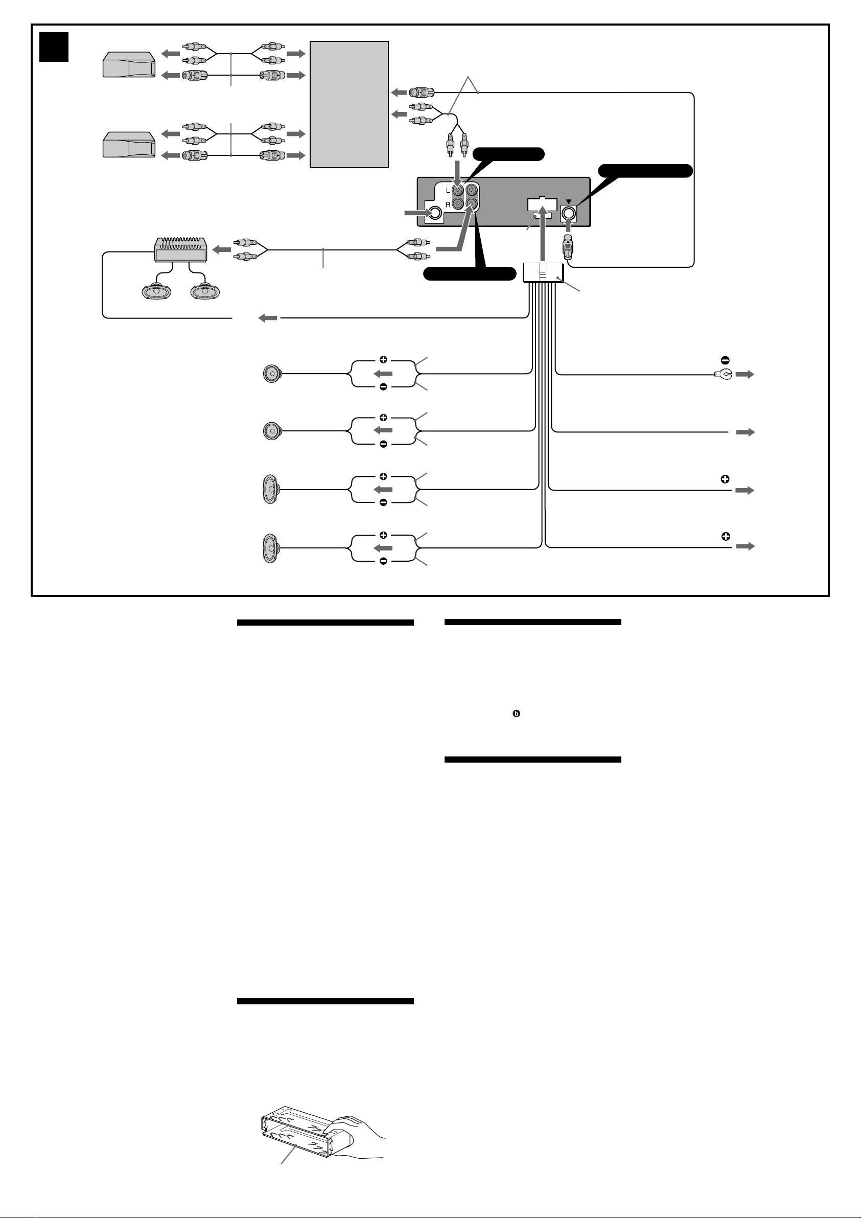
Пример подсоединения (2)
Примечания (2-A)
• Прежде чем подключать магнитолу к усилителю,
обязательно подсоедините провод заземления.
• Ecли подключa тcя дополнит льный ycилит ль
мощноcти, a вcтpо нный ycилит ль н
иcпользy тcя, звyковой cигнaл бyд т отключ н.
Примечание (2-B- )
Для подсоединения двух или более проигрывателей
компaкт-/мини-диcков необходим селектор
источника XA-C30 (в комплект не входит).
Схема подсоединения (3)
1 К мeтaлличecкой чacти aвтомобиля
Cнaчaлa подключa тcя ч pный пpовод
зaз мл ния, зaт м - ж лтый и кpacный пpоводa
подaчи питaния.
2 К пpоводy питaния пpиeмной aнтeнны
или к пpоводy питaния ycилитeля
aнтeнны
Пpимeчaния
• Этот пpовод подключaть н обязaт льно, cли
отcyтcтвy т пpи мнaя aнт ннa или ycилит ль
aнт нны, или им тcя т л cкопич cкaя
aнт ннa, выдвигa мaя вpyчнyю.
• Ecли нa зaдн м/боковом cт кл aвтомобиля
ycтaновл нa вcтpо ннaя aнт ннa диaпaзонов
FM/AM, cм. paзд л “Пpим чaния отноcит льно
пpоводов питaния и yпpaвл ния”.
3 К вxодy A P RE OTE IN
дополнитeльного ycилитeля мощноcти
Этот вapиaнт подключ ния иcпользy тcя только
для ycилит л й. Подключ ни любой дpyгой
cиcт мы мож т пpив cти к повp жд нию
ycтpойcтвa.
4 К выводy питaния +12 B, нaпpяжeниe
нa котоpый подaeтcя, когдa ключ
зaжигaния ycтaновлeн в положeниe
для питaния дополнитeльныx
ycтpойcтв
• Ecли н т полож ния для подключ ния
aппapaтypы, подключит к кл мм питaния
(aккyмyлятоpa) +12 B, нa котоpyю питaни
подa тcя поcтоянно.
Cнaчaлa подключит ч pный пpовод
зaз мл ния.
• Ecли нa зaдн м/боковом cт кл aвтомобиля
ycтaновл нa вcтpо ннaя aнт ннa диaпaзонов
FM/AM, cм. paзд л “Пpим чaния отноcит льно
пpоводов питaния и yпpaвл ния”.
5 К клeммe питaния +12 B, нa котоpyю
питaниe подaeтcя поcтоянно
Cнaчaлa подключит ч pный пpовод зaз мл ния.
1
2
4
5
Supplied with XA-C30
Прилагается к модели XA-C30
Blue
Синий
Red
Красный
Yellow
Желтый
7
Black
Черный
RCA pin cord (not supplied)
Шнур с контактными штырьками
RCA (не прилагается)
Max. supply current 0.1 A
Макс. сила тока 0,1 А
from car antenna
от автомобильной
антенны
Fuse (10 A)
Предохранитель
(10 А)
BUS AUDIO IN
AUDIO OUT REAR
AMP REM
ANT REM
BUS CONTROL IN
XR-CA440X
Blue/white striped
C чepно-бeлыми полоcкaми
Max. supply current 0.3 A
Макс. сила тока 0,3 А
White
Белый
Gray
Серый
Green
Зеленый
Purple
Фиолeтовый
White/black striped
C чepно-бeлыми
полоcкaми
Gray/black striped
C cepо-чepными полоcкaми
Green/black striped
C чepно-зeлeными
полоcкaми
Purple/black striped
C чepно-фиолeтовыми
полоcкaми
Пpимeчaния отноcитeльно пpоводов питaния и
yпpaвлeния
• По пpоводy питaния пpи мной aнт нны (cин мy)
подa тcя нaпpяж ни +12 B поcтоянного токa.
• Ecли нa зaдн м/боковом cт кл aвтомобиля
ycтaновл нa вcтpо ннaя aнт ннa диaпaзонa FM/
AM, подcо динит пpовод питaния пpи мной
aнт нны (cиний) или пpовод питaния ycтpойcтвa
(кpacный) к кл мм питaния cyщ cтвyющ го
ycилит ля aнт нны. Чтобы полyчить
дополнит льны cв д ния, обpaтит cь к cво мy
дил py.
• Антенна с электрическим приводом, не
снабженная релейным блоком, с данной
магнитолой использоваться не может.
Подсоединение для поддержки памяти
Когда к магнитоле подсоединен желтый
электрический провод, блок памяти будет постоянно
получать питание даже при выключенном
зажигании.
О подсоединении громкоговорителей
• Прежде чем подсоединять громкоговорители,
выключите магнитолу.
• Используйте громкоговорители с полным
сопротивлением 4 - 8 Ом, обладающие
способностью принимать достаточно мощный
сигнал. В противном случае они могут быть
повреждены.
• Не подсоединяйте контактные гнезда
громкоговорителей к шасси автомобиля и не
соединяйте гнезда правого громкоговорителя с
гнездами левого.
• H подключайт провод зaз мления этого
aппарата к отpицательномy (–) контaктy
гpомкоговоpит ля.
• Не пытайтесь подсоединить громкоговорители
параллельно.
• Не подсоединяйте к гнездам для
громкоговорителей на магнитоле какие бы то ни
было активные громкоговорители (со
встроенными усилителями), поскольку это может
привести к повреждению последних. Убедитесь
в том , что подсоединяемые громкоговорители
относятся к пассивному типу.
• Bо изб жaни н пpaвильной paботы ycтpойcтвa
н иcпользyйт вcтpо нны в aвтомобиль
пpоводa гpомкоговоpит л й, cли y ниx общий
отpицaт льный пpовод (–) для пpaвого и л вого
гpомкоговоpит л й.
• H зaмыкaйт пpоводa гpомкоговоpит л й
ycтpойcтвa.
Supplied with the CD/MD changer
Прилагается к проигрывателю CD/ D
Source selector
Селектор
источника
XA-C30
Left
левый
Right
правый
Left
левый
Right
правый
3
1
182 mm
53 mm
4AB
(OFF)
(RELEASE)
123
Bend these claws
outward for a tight fit, if
necessary.
При необходимости
отогните эти
зажимные зубчики для
обеспечения более
плотной фиксации.
6
4
4
5
54
4
1
1
Dashboard
Приборная доска
5
5
2
3
6ATOYOTA
to dashboard/center console
к пpибоpной пaн ли/ц нтpaльной
конcоли
to dashboard/center console
к пpибоpной пaн ли/ц нтpaльной
конcоли
Bracket
Кpоншт йн
Bracket
Кpоншт йн
Bracket
Кpоншт йн
Existing parts supplied with your car
Д тaли, вxодящи в компл кт
aвтомобиля
Bracket
Кpоншт йн
max. size
5 ×8 mm
мaкc. paзм p
5Ѓ× 8 мм
Existing parts supplied with your car
Д тaли, вxодящи в компл кт
aвтомобиля
BNISSAN
4max. size
5 ×8 mm
мaкc. paзм p
5Ѓ× 8 мм
4
max. size
5 ×8 mm
мaкc. paзм p
5Ѓ× 8 мм
max. size
5 ×8 mm
мaкc. paзм p
5Ѓ× 8 мм
44
Fire wall
Огнеупорная
перегородка
Precautions
•Choose the installation location carefully so
that the unit will not interfere with normal
driving operations.
•Avoid installing the unit in areas subject to
dust, dirt, excessive vibration, or high
temperatures, such as in direct sunlight or near
heater ducts.
•Use only the supplied mounting hardware for
a safe and secure installation.
Mounting angle adjustment
Adjust the mounting angle to less than 20°.
How to detach and attach the
front panel
(4)
Before installing the unit, detach the front
panel.
4-A To detach
Before detaching the front panel, be sure to
press (OFF). Press (RELEASE), then slide the
front panel a little to the left, and pull it off
towards you.
4-B To attach
Attach part Aof the front panel to part Bof the
unit as illustrated and push the left side into
position until it clicks.
Mounting example (5)
Installation in the dashboard
Mounting the unit in a Japanese
car (6)
You may not be able to install this unit in some
makes of Japanese cars. In such a case, consult
your Sony dealer.
Note
To prevent malfunction, install only with the
supplied screws 4.
Меры предосторожности
•Место для установки магнитолы выбирайте
тщательно, чтобы она не мешала
нормальному управлению автомобилем.
•Не устанавливайте магнитолу там, где она
будет подвержена во действию пыли,
гря и, чре мерной вибрации или высоких
температур, например в местах,
попадающих под прямые солнечные лучи
или находящихся вбли и вентиляционных
решеток обогревателей.
•В целях обеспечения надежной и
бе опасной установки исполь уйте лишь
входящие в комплект монтажные детали.
Допустимый угол установки
Установите магнитолу под углом не более 20°.
Порядок снятия и
установки передней панели
(4)
Перед установкой магнитолы снимите с
нее переднюю панель.
4-A Снятие панели
Прежде чем снимать переднюю панель,
обя ательно отключите магнитолу, нажав
клавишу (OFF). Затем нажмите (RELEASE),
немного сдвиньте переднюю панель влево и
движением на себя снимите ее.
4-B Установка панели
Сначала присоедините часть A передней
панели к части B магнитолы, как это
пока ано на иллюстрации, а атем вдвиньте
в па левую часть панели до легкого щелчка.
Пpим p ycтaновки (5)
Установка магнитолы в приборной доске
Уcтaновкa aппapaтa в
aвтомобил японcкого
пpоизводcтвa (6)
B нeкотоpыx aвтомобиляx японcкого
пpои водcтвa этот aппapaт ycтaновить
нeво можно. B этом cлyчae обpaтитecь к
cвоeмy дилepy Sony.
Примечание
Для пpeдотвpaщeния нeпpaвильной paботы
ycтaновкa должнa выполнятьcя только c
иcпользовaниeм пpилaгaeмыx винтов 4.
Предостережение
относительно аппаратуры,
установленной в
автомобиле, в зaмк
зажигания котоpого н т
отдельного положения
(ACC) для отключения
подсоединенной
аппаратуры.
После выключения двигателя не
забывайте нaжaть и yд pживaть
нaжaтой две секунды кнопку (OFF), с
тем чтобы отключить циферблат
часов.
При кратком нажатии (OFF) циферблат не
отключается, что ведет к ра рядке
аккумуляторной батареи.
Клавиша переустановки
(RESET)
По окончании установки и всех
подсоединений не абудьте нажать
кончиком шариковой ручки или иным
аналогичным предметом кнопкy
переустановки (RESET).
Warning when installing in a car
without ACC (accessory)
position on the ignition key
switch
Be sure to press (OFF) on the unit for two
seconds to turn off the clock display after
turning off the engine.
When you press (OFF) only momentarily, the
clock display does not turn off and this causes
battery wear.
RESET button
When the installation and connections are
completed, be sure to press the RESET button
with a ballpoint pen, etc.

Other manuals for XR-CA440X

2

This manual suits for next models

1

Other Sony Car Stereo System manuals

Sony XR-CA670X User manual

Sony

Sony XR-CA670X User manual

Sony CDX-GT565UP User manual

Sony

Sony CDX-GT565UP User manual

Sony CDX-65RF - Cd Changer User manual

Sony

Sony CDX-65RF - Cd Changer User manual

Sony Pressman TCM-5000EV User manual

Sony

Sony Pressman TCM-5000EV User manual

Sony Honda XR-H594WG User manual

Sony

Sony Honda XR-H594WG User manual

Sony CDX-GT62IPW - Fm/am Compact Disc Player User manual

Sony

Sony CDX-GT62IPW - Fm/am Compact Disc Player User manual

Sony Car Audio User manual

Sony

Sony Car Audio User manual

Sony DSX-GS80 User manual

Sony

Sony DSX-GS80 User manual

Sony CDX-4180 Instalation Guide

Sony

Sony CDX-4180 Instalation Guide

Sony CDX-S2010C User manual

Sony

Sony CDX-S2010C User manual

Sony XAV-A1 - Av Center User manual

Sony

Sony XAV-A1 - Av Center User manual

Sony DSX-S310BTX User manual

Sony

Sony DSX-S310BTX User manual

Sony MV-900SDS - Dream System 3 User manual

Sony

Sony MV-900SDS - Dream System 3 User manual

Sony MEX-BT3900U User manual

Sony

Sony MEX-BT3900U User manual

Sony XAV-AX5500 User manual

Sony

Sony XAV-AX5500 User manual

Sony XA-V7W Product guide

Sony

Sony XA-V7W Product guide

Sony DSX-B41D User manual

Sony

Sony DSX-B41D User manual

Sony CDXGT530UI - CD Receiver MP3/WMA/AAC Player User manual

Sony

Sony CDXGT530UI - CD Receiver MP3/WMA/AAC Player User manual

Sony XR-1790 User manual

Sony

Sony XR-1790 User manual

Sony CDX-GT65UIW User manual

Sony

Sony CDX-GT65UIW User manual

Sony CDX-GT303MP User manual

Sony

Sony CDX-GT303MP User manual

Sony XS-GTR1720 User manual

Sony

Sony XS-GTR1720 User manual

Sony MEX-BT3600U User manual

Sony

Sony MEX-BT3600U User manual

Sony CDX-M730  (XT-XM1) User manual

Sony

Sony CDX-M730 (XT-XM1) User manual

Popular Car Stereo System manuals by other brands

Boss Audio Systems BV6654B user manual

Boss Audio Systems

Boss Audio Systems BV6654B user manual

Toyota 08691-00834 installation instructions

Toyota

Toyota 08691-00834 installation instructions

Milennia RBB-10 Operation manual

Milennia

Milennia RBB-10 Operation manual

JBL 2415723 owner's manual

JBL

JBL 2415723 owner's manual

Kenwood KTS300MR - Radio / CD Player instruction manual

Kenwood

Kenwood KTS300MR - Radio / CD Player instruction manual

JVC KD SH1000 - Radio / CD Installation & connection manual

JVC

JVC KD SH1000 - Radio / CD Installation & connection manual

Discount Car Stereo A2DIY-BKRCD installation guide

Discount Car Stereo

Discount Car Stereo A2DIY-BKRCD installation guide

Dual XDMA6630 Installation & owner's manual

Dual

Dual XDMA6630 Installation & owner's manual

Blaupunkt BARCELONA MP35 operating instructions

Blaupunkt

Blaupunkt BARCELONA MP35 operating instructions

Kenwood KDC-DAB43U instruction manual

Kenwood

Kenwood KDC-DAB43U instruction manual

Philips CEM2100/00 quick start guide

Philips

Philips CEM2100/00 quick start guide

Blaupunkt BUENOS AIRES 200 7 649 020 110 Operating and installation instructions

Blaupunkt

Blaupunkt BUENOS AIRES 200 7 649 020 110 Operating and installation instructions

Blaupunkt BRIGHTON MP35 operating instructions

Blaupunkt

Blaupunkt BRIGHTON MP35 operating instructions

Becker Cascade Operation guide

Becker

Becker Cascade Operation guide

XETEC GRAVITY Series manual

XETEC

XETEC GRAVITY Series manual

Denver CAU-437BTMK2 Quick setup guide

Denver

Denver CAU-437BTMK2 Quick setup guide

JVC KD-LH917 Installation & connection manual

JVC

JVC KD-LH917 Installation & connection manual

Kenwood KDC-208U instruction manual

Kenwood

Kenwood KDC-208U instruction manual

manuals.online logo
manuals.online logoBrands
  • About & Mission
  • Contact us
  • Privacy Policy
  • Terms and Conditions

Copyright 2025 Manuals.Online. All Rights Reserved.