manuals.online logo
Brands
  1. Home
  2. •
  3. Brands
  4. •
  5. Sony
  6. •
  7. Cassette Player
  8. •
  9. Sony TC-WR545 Primary User manual

Sony TC-WR545 Primary User manual

SERVICE
MANUAL
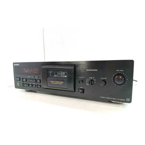
Photo
:
TC-WR545
TC-WR45/WR741
US
Model
Canadian
Model
TC-WR545/WR74
1
AEP
Model
UK
Model
E
Model
Australian
Model
TC-WR545
Model
Name
Using
Similar
Mechanism
|
TC-WR535
Tape
Transport
Machanism
Type
DECK
A}
TCM-190RA12CL
TCM-WR545
:
TCM-190RB12CL
DECK
B
TCM-WR741
:
TCM-190RB52C
SPECIFICATIONS
4-track
2-channel
stereo
Approx.
90
sec.
(with
Sony
C-60
cassette)
Bias
|
AC
bias
Signal-to-noise
ratio
(at
peak
level
and
weighted)
Cassette
Type
IV
Type
Il
Type
I
(Dolby
NR
OFF)
58
dB
57
dB
55
dB
S/N
ratio
improved
(approximate
values)
with
Dolby
B
NR
on:
5
dB
at
1
kHz;
10
dB
at
5
kHz
with
Dolby
C
NR
on:
15
dB
at
500
Hz;
20
dB
at
1
kHz
Recording
system
Fast
winding
time
Harmonic
distortion
0.4%
(with
Sony
Type
I,
160
nWb/m,
315
Hz,
3rd
H.D.)
1.8%
(with
Sony
Type
IV,
250
nWb/m,
315
Hz,
3rd
H.D.)
Frequency
response
(Dolby
NR
OFF)
Type
IV
Type
I
Type
lI
cassette
cassette
cassette
30
-
18,000
Hz
}30-
17,000
Hz
|
30
-
15,000
Hz
(43
dB,
TEC)
{G@3dB,IEC)
|
(43
dB,
IEC)
30
-
13,000
Hz
[+3
dB
(-4
dB)
recording]
Type
IV:
Sony
Type
IV
(METAL)
Type
Il:
Sony
Type
IJ
(HIGH)
Typel:
Sony
Type
I
(NORMAL)
Wow
and
flutter
+0.14%
W.Peak
(IEC)
0.08%
W.RMS
(NAB)
+0.19%
W.Peak
(DIN)
—
Continued
on
page
2
—
Dolby
noise
reduction
manufactured
under
license
from
Dolby
Laboratories
Licensing
Corporation.
“DOLBY”
and
the
double-D
symbol
90
are
trademarks
of
Dolby
Laboratories
Licensing
Corporation.
STEREO
CASSETTE
DECK
SONY.
Inputs
(phono
jacks)
Input
impedance
47
k
ohms
Outputs
Line
outputs
(phono
jacks)
0.5
V
ata
load
impedance
of
47
k
ohms
Load
impedance
|
Over
10
k
ohms
Output
level
1
mW
at
a
load
impedance
of
32
ohms
US,
Canadian
model
:
120V
AC,
60Hz
UK
model
:
240V
AC,
50Hz
Australian
model
:
240V
AC,
50/60Hz
AEP,
German
model
:
220-230V
AC,
50/60Hz
E
model
:
120,
220
or
240V
AC
adjustable,
50/60Hz
25W
EXCEPT
UK,
Australian
model
:
Approx.
430
x
123
x
290
mm
(w/h/d)
(17
x
47/s
x
11
!/2
inches)
UK,
Australian
model
:
Approx.
430
123x300
mm
(w/h/d)
(17X474x
117A
inches)
including
projecting
parts
and
controls
Approx.
4.5
kg
(9
Ibs
15
0z)
Rated
output
level
Headphones
(stereo
phone
jack)
(TC-WR545
only)
General
Power
requirements
Power
consumption
Dimensions
Mass
Supplied
accessories
Audio
connecting
cords
(2)
Design
and
specifications
are
subject
to
change
without
notice.
MODEL
IDENTIFICATION
(Specification
Label)
SONY:
STEREO
CASSETTE
DECK
MODEL
NO.
Rss
aaa
:
AC
120V
60Hz
US,
Canadian
model
UK
model
:
AC
240V
50Hz
Australian
model!
:
AC
240V~50/60Hz
AEP,
German
model
:
AC
220-230V~50/60Hz
E
model
:
AC120,
220,
240V~50/60Hz
TABLE
OF
CONTENTS
Section
Title
Page
Specifications
:++seresesesereeeeteeteeeeteereeteese
teeter
eseeeseees
l
Safety
Check-out
(US
Model)
SOrPereeeereeer
re
rere
rere rere
rr
eee)
3
1.
GENERAL
Identifying
the
Parts
on
the
Front
Panel
s++r+t++trrrsrrtetttteee
4
2.
DISASSEMBLY
2-1
.
Front
Panel
errr
rrr
errr tree
rere
ee
ee
eee
eee
ee
eee
5
2-2.
Mechanism
Deck
eer
rr
rrr
rer
rr
rrr
rr
errr
rere
rrr
reer
reece
5
2-3.
Capstan
Motor,
Reel
Motor
ssrrrrtrrrtrrerritrsisesessee
6
2-4.
Head,
Pinch
Rollers::sssressrereertseeeeeeeeeteeeneeeeneeeey
6
3.
ADJUSTMENTS
3-1.
Mechanical
Adjustments
:+rrrsttrrrrrereertrsereterseersersees
ay
3-2.
Electrical
Adjustments
«-++1+esseseereeeeeteeterteerierieees
7
4.
EXPLANATION
OF
IC
TERMINALS
--+-e
erste
11
5.
DIAGRAMS
5-1.
Block
Diagram
cece
ener
enon
scree
teen
rset
ne
enereeseeenonsesecure
13
522)
Circuit
Board
Location
Sererrerrrrrr
rrr
errr
errr
e
rrr
16
5-3.
Printed
Wiring
Boards
(System
Control
Section)-++++--
17
5-4.
Schematic
Diagram
(System
Control
Section):**+*+++*-
21
5-5.
Schematic
Diagram
(Audio
Section)
srrrrsrrrrtrrtttrerees
27
5-6.
Printed
Wiring
Boards
(Audio
Section):**++rstrtrrete"*
ep
6.
EXPLODED
VIEWS
6-1.
Chassis
Section
eee
e
cece
tere
nme eee
e
aren
eee
sereesenereneueeeenes
37
6-2.
Front
Panel
Section
Deemer
meen
e
nse
et
tere
an
nsosscoesesaeeeseeee
39
6-3.
Mechanism
Section
l
deere
ence
recone
eta
a
en
eee
nese
e
seen
enee
40
6-4.
Mechanism
Section
2esrrcerersssseerteseeteeeeecesessenennes
A]
7.
ELECTRICAL
PARTS
LIST
-sr--:ceecceceeceeeeseeeeeeeeeerees
42
TC-WR545,
TC-WR741
SAFETY
CHECK-OUT
(US
Model)
After
correcting
the
original
service
problem,
perform
the
following
safety
check
before
releasing
the
set
to
the
customer:
Check
the
antenna
terminals,
metal
trim,
“‘metallized”’
knobs,
screws,
and
all
other
exposed
metal
parts
for
AC
leakage.
Check
leakage
as
described
below.
LEAKAGE
TEST
The
AC
leakage
from
any
exposed
metal
part
to
earth
ground
and
from
all
exposed
metal
parts
to
any
exposed
metal
part
having
a
return
to
chassis,
must
not
exceed
0.5mA
(500
microampers).
Leakage
current
can
be
measured
by
any
one
of
three
methods.
1.
A
commercial
leakage
tester,
such
as
the
Simpson
229
or
RCA
WT-540A.
Follow
the
manufacturers’
instructions
to
use
these
instru-
ments.
2.
<A
battery-operated
AC
milliammeter.
The
Data
Precision
245
digital
multimeter
is
suitable
for
this
job.
SAFETY-RELATED
COMPONENT
WARNING!!
COMPONENTS
IDENTIFIED
BY
MARK
A
OR
DOTTED
LINE
WITH
MARK
A
ON
THE
SCHEMATIC
DIAGRAMS
AND
IN
THE
PARTS
LIST
ARE
CRITICAL
TO
SAFE
OPERATION.
REPLACE
THESE
COMPONENTS
WITH
SONY
PARTS
WHOSE
PART
NUMBERS
APPEAR
AS
SHOWN
IN
THIS
MANUAL
OR
IN
SUPPLEMENTS
PUB-
LISHED
BY
SONY.
3.
Measuring
the
voltage
drop
across
a
resistor
by
means
of
a
VOM
or
battery-operated
AC
volt-
meter.
The
“limit”
indication
is
0.75
V,
so
analog
meters
must
have
an
accurate
low-
voltage
scale.
The
Simpson
250
and
Sanwa
SH-63Trd
are
examples
of
a
passive
VOM
that
is
suitable.
Nearly
all
battery
operated
digital
multimeters
that
have
a
2V
AC
range
are
suitable.
(See
Fig.
A)
To
Exposed
Metal
Parts
on
Set
AC
voltmeter
ialagee
(0.75
V)
=
Earth
Ground
Fig.
A.
Using
an
AC
voltmeter
to
check
AC
leakage.
ATTENTION
AU
COMPOSANT
AYANT
RAPPORT
A
LA
SECURITE!
LES
COMPOSANTS
IDENTIFIES
PAR
UNE
MARQUE
/\
SUR
LES
DIAGRAMMES
SCHEMATIQUES
ET
LA
LISTE
DES
PIECES
SONT
CRITIQUES
POUR
LA
SECURITE
DE
FONCTIONNEMENT.
NE
REMPLACER
CES
COM.-
POSANTS
QUE
PAR
DES
PIECES
SONY
DONT
LES
NUMEROS
SONT
DONNES
DANS
CE
MANUEL
OU
DANS
LES
SUPPLEMENTS
PUBLIES
PAR
SONY.
SECTION
1
This
section
is
extracted
from
GENERAL
instruction
manual.
Identifying
the
Parts
on
the
Front
Panel
|
Remote
control
sensor*
3}
14)
15]
16)
[7J18I19)
18)
17) 16) 15)
[14
(The
illustration
shows
the
TC-WR545.)
For
details,
refer
to
the
page
number(s)
indicated
in
parentheses.
POWER
switch
Tape
operation
buttons
Deck
A
<4
(leftward
fast-winding)/AMS***/RMS**—
button
[3]
COUNTER
RESET
button
(deck
A)
PP
(rightward
fast-winding)/AMS***/RMS**+
button
RMS
operation
buttons
(TC-WR545
only)
Mi
(stop)
/(RMS**)
CLEAR
button
RMS/START
button
<]
(reverse
play)
/(RMS**)
BACK
button
SET
button
[>
(forward
play)
/(RMS**)
FRONT
button
CHECK
button
If
PAUSE
button
(deck
B
only)
DISPLAY
button
O
REC
MUTE
(record
muting)
button
(deck
B
only)
Display
panel
@
REC
(recording)
button
(deck
B
only)
[6]
AUTO
CAL
button
(TC-WR545
only)
[14]
MPX
FILTER
switch
(TC-WR545
only)
COUNTER
RESET
button
(deck
B)
DOLBY
NR
(Dolby
noise
reduction)
switch
SYNCHRO
DUBBING
buttons
DIR
(direction)
MODE
switch
HIGH
button
PHONES
jack
(stereo
phone
jack)
(TC-WR545
only)
NORMAL
button
&
(eject)
button
(deck
A)
[9]
REC
(recording)
LEVEL
control
Deck
B
*
Remote
control
sensor
BALANCE
control
You
can
remotely
control
this
cassette
deck
with:
(12)
&
(eject)
button
(deck
B)
—
A
remote
commander
that
came
with
a
Sony
amplifier
or
receiver
if
it
has
the
f
mark
and
cassette
deck
control
capability.
—
Any
optional
Sony
remote
commander
with
the
EJ
mark
and
cassette
deck
control
capability.
**
Random
Music
Sensor
(TC-WR545
only)
“**
Automatic
Music
Sensor
6
SECTION
2
DISASSEMBLY
|
2-3.
CAPSTAN
MOTOR,
REEL
MOTOR
Note
:
Follow
the
disassembly
procedure
in
the
numerical
order
given.
@
+PTPWh2
x
23
CASE
Unscrew
the
four
case
attachment
screws
M3
X
8
and
remove
the
case.
2-1.
FRONT
PANEL
\
@
Fitting
base
E
model
only
FRONTPANEL
@-
©
VOLTAGE
SELECTOR
When
installing,
pull
the
FR
i)
capstan
belt
and
put
and
put
around
claws.
When
installing,
pull
the
|
around
claws.
VOLTAGE
SELECTOR
@
Remove
the
flat
cable.
©
Remove
the
front
Panel
@
claw
@
Connectors
@
Capstan
motor
M1
(DECK
A)
M3
(DECK
B)
Ground
plate
2-2,
MECHANISM
DECK
@
MD(A)board
(DECK
A)
MD(C)board
(DECK
B)
@
Press
the
EJECT
button.
@
Reel
motor
M2
(DECK
A)
M4
(DECK
B)
Remove
the
cassette
holder
Belt
(FR)
©
+P2.6x28
2-4.
HEAD,
PINCH
ROLLER
@
Cassette
lid
3]
Claw
©
BVIP2.6x8
1)
Claw
@
Head
base
assy
HP101(DECK
A)
HRPE101(DECK
B)
Mechanism
deck
6
:
@
BVTP2.6
x
8
@
Lever
(pinch
lever
REV)
assy
@
Lever
(pinch
lever
FWD)
assy
SECTION
3
ADJUSTMENTS
3-1.
MECHANICAL
ADJUSTMENTS
PRECAUTION
1.
Clean
the
following
parts
with
a
denatured
alcohol-moistened
swab:
record/playback/erase
head
rubber
belts
idlers
2.
Demagnetize
the
record/playback
head
with
a
head
demagnetizer.
(Head
demagnetizer
do
not
approach
for
the
erase
head.)
3.
Do
not
use
a
magnetized
screwdriver
for
the
adjustment.
4.
After
the
adjustments,
apply
suitable
locking
compound
to
the
parts
adjusted.
5.The
adjustments
should
be
performed
with
the
rated
power
supply
voltage
unless
otherwise
noted.
pinch
roller
capstan
Torque
Measurement
Meter
reading
30
to
65g
*
cm
CQ-102C
(0.42
to
0.9
oz
*
inch)
Forward
DECK
A:
1
to
6g
*
cm
(0.014
to
0.083
oz
¢
inch)
Forward
back
tension
Reverse
back
tension
FF/REW
CQ-201B
3-2.
ELECTRICAL
ADJUSTMENTS
CQ-102C
DECK
B
:
2
to
9g
*
cm
(0.03
to
0.12
oz
*
inch)
30
to
65g
*
cm
(0.42
to
0.9
oz
*
inch)
1
to
6g
*cm
SOneR
(0.014
to
0.083
02
«
inch)
70
to
120g*cm
(0.98
to
1.66
ozeinch)
PRECAUTION
1.
The
adjustment
should
be
performed
in
the
publication.
(Be
sure
to
male
playback
adjustment
at
first.)
2.
The
adjustments
and
measurement
should
be
performed
for
both
L-CH
and
R-CH.
@
Switch
position
DOLBY
NR
switch
:
OFF
DIR
MODE
switch
=
®
Standard
record
position
:
Deliver
the
standard
input
signal
level
to
input
jack
and
set
the
REC
LEVEL
control
to
obtain
the
standard
output
signal
level
as
follows.
—
Record
Mode
—~
AF
OSC
VTVM
Q
attenuator
10k
Q
ono
oF
I]
ooo
|
[cee
|
LINE
OUT
LINE
IN
Standard
Input
Level
source
impedance
input
signal
level
0.5V
(
—
3.8dB)
Standard
Output
Level
Output
terminal
LINE
OUT
output
signal
level
0.5V
(
—
3.8dB)
Test
Tape
.
|_Tape
|
Contents
|
Use
P-4-A
100
10kHz,
—
10dB
Azimuth
Adjustment
P-4-L300
315Hz,
0dB
PB
Level
Adjustment
WS-48B
3kHz,
0dB
Tape
Speed
Adjustment
OdB=0.775V
Test
Mode
1.
Insert
a
short-circuit
plug
into
TP801
(2P)
and
turn
ON
the
power
switch.
(Earth
pin
9
of
IC801
and
turn
ON
the
power
switch.)
At
first,
all
the
fluorescent
tubes
light
up,
then
the
system
returns
to
normal
display.
(However,
“OOOO”
is
not
displayed
on
the
counter.
)
2.
To
release
the
test
mode,
remove
the
short
plug
and
turn
off
the
power
switch.
3.
Remove
the
short
plug
after
completion
of
adjustment.
Record/Playback
Head
Azimuth
Adjustment
Procedure
:
1.
Forward
playback
Mode
test
tape
P-4-A100
(10kHz,
—
10dB)
VTVM
LINE
OUT
2.
Turn
the
adjustment
screw
for
the
maximum
output
levels.
If
these
levels
do
not
match,
turn
the
adjustment
screw
until
both
of
output
levels
match
together
within
1dB.
L-CH
peak
within
ix
R-CH
peak
Screw
—
screw
position
position
L-CH
R-CH
3.
Playback
Mode
test
tape
P-4-A100
(10kHz,
—
10dB)
oscilloscope
nphase
45°
rT
j
good
4,
Change
the
reveres
playback
mode
and
repeat
the
steps
1
to
3.
5.
After
the
adjustment,
lock
the
adjustment
screws
with
suitable
locking
compound.
Adjustment
Location
:
—
record/playback
head
—
reverse
side
forward
side
adjustment
screws
Tape
Speed
Adjustment
Procedure
:
—
Forward
Playback
Mode
—
test
tape
WS-48B
(3kHz,
OaB)
LINE
OUT
(high
speed
adjustment)
1.
Connect
@
pin
of
IC801
to
ground.
2.
Set
to
FWD
playback
mode.
3.
Keep
on
pressing
the
HIGH
SPEED
DUBBING
switch.
4.
Adjust
RV72
so
that
the
frequency
counter
reading
becomes
6,000
+
20Hz.
(normal
speed
adjustment)
1.
Set
to
FWD
playback
mode.
2.
Adjust
RV71
so
that
the
frequency
counter
reeding
becomes
3,000
+
10Hz.
Frequency
difference
between
the
beginning
and
the
end
of
the
tape
should
be
within
3%.
Frequency
difference
between
the
deck
A
and
deck
B
the
beginning
of
the
tape
should
be
within
1.5%.
Adjustment
Location
:
AUDIO
board
Playback
Level
Adjustment
Procedure
:
—
Forward
Playback
Mode
—
test
tape
P-4-L300
(315Hz,
0dB)
LINE
OUT
Adjust
RV11(L-CH)
and
RV21(R-CH)
so
the
VITVM
reading
becomes
the
adjustment
limits
below.
Adjustment
Value
:
LINE
OUT
level
:
—
7.7
=
0.5dB
(0.301
to
0.338V)
Level
difference
between
channels
:
within
0.5dB
Confirm
the
LINE
OUT
level
does
not
change
in
playback
mode
while
changing
the
mode
from
playback
to
stop
several
times.
Adjustment
Location
:
AUDIO
board
Bias
Consumption
Current
Adjustment
(TC-WR545
only)
This
adjustment
should
be
performed
when
replacing
the
head
assy
or
the
bias
oscillating
transformer
(T81,
T91).
Procedure
:
():R-CH
a
-
digital
biank
tape
voltmeter
CS-413
|
set
a
atl
LINE
IN
ne
signal
1..Connect
the
digital
voltmeter
to
test
point
TP81.
2.
Set
RV81
(RV91)
to
mechanical
center.
3.
Set
to
FWD
record
mode.
4,
Adjust
T81
(T91)
so
that
the
digital
voltmeter
reading
becomes
minimum.
oe
Adjustment
Value
:
Maximum
220mV
Adjustment
Location
:
AUDIO
board
Record
Bias
Adjustment
Setting
:
REC
LEVEL
control
:
standard
record
position
(Refer
to
page
7.)
Procedure
:
1.
Record
Mode
AF
OSC
blank
tape
CS-123
foe
|
SI
}
38.8mV(
—
260B)
LINE
IN
1)
315Hz
2)
10KHz
2.
Playback
Mode
.
VIVM
recorded
portion
ic
Confirm
that
the
1OkHz
playback
output
is
0
+
0.5dB
relative
to
the
315Hz
output.
If
necessary,
adjust
RV81
(L-CH),
RV9
1(R-CH)
:
TC-WRS545,
RV12
(L-CH),
RV22
(R-CH)
:
TC-WR741
and
repeat
the
steps
given
above.
Adjustment
Location
;
AUDIO
board
Record
Level
Adjustment
Setting
:
REC
LEVEL
control
:
standard
record
position
(Refer
to
page
7.)
Procedure
:
1.
Record
Mode
AF
OSC
blank
tape
e
CS-123
oO
GVV——
o—o
—
i>
2.
Playback
Mode
recorded
VITVM
portion
ic
Confirm
playback
the
tape
recorded
become
adjustment
level
as
follows.
If
necessary,
adjust
RV101(L-CH),
RV201(R-CH)
and
repeat
the
steps
1
and
2.
LINE
OUT
Adjustment
Value
:
LINE
OUT
level:
—
26
+
0.5dB
(36.7
to
41.1mV)
Adjustment
Location
:
MAIN
board
—
Adjustment
Parts
Location
Diagrams
—
{SYSTEM
CONTROL
BOARD)
Record
Level
oF
(1)
(R)
RVIO!
RVzZ201
DECK-A
:
[AUDIO
BOARD)
DECK-B
:
TC-WR545
{AUDIO
BOARD]
Bias
Consumption
Current
Record
Blas
en
(R)
(L)
AV9I
RVE8I
RV72
(HIGH)
RV71
(NORMAL)
RV72
(HIGH)
RV71
(NORMAL)
RV21
(R)
AVIT
(L)
T91
(R)
RvV21
(R)
RVit
(L)
Tape
speed
Playback
Level
Tape
speed
Current
DECK-B
:
TC-WR741
{AUDIO
BOARD)
Tere)
Bias
Consumption
Playback
Level
Bias
Consumption
Current
Record
Bias
en
(A)
RV22 AVI2
RV72
(HIGH)
Tape
speed
RV71
(NORMAL)
Playback
Level
RV21
(R)
AVIT
(L)
SECTION
4
EXPLANATION
OF
IC
TERMINALS
IC801
CXP82316-039Q
OQ
SIRCS
IN
POWER
IN
SPEED
H/L
A/B
NRO
NRI1
MODE1
MODE2
10
POWER
OUT
LIN
MUTE
IC
MUTE
REALY
REC/PB
REC
CALO
REC
CALI
EQ
CALO
EQ
CALI
BIAS
(B)
Sires
signal
in
terminal.
I]
Power
OFF.
OFF
=
OV
Power
ON/OFF.
Line
mute
ON/OFF.
“L”:ON
Meter
mute.
“H”:ON
Recording/Playback
selector
at
DECK-B.
“L”:
Recording
Recording
calibration.
“H”:ON
| |
Bias
ON/OFF
at
DECK-B.
“H”:ON
Test
mode
terminal.
“L”
:
Test
mode,
“H”
:
Normal
mode
E
4
tw
iC)
a
19
20
METAL(B)
70
w
(B)
A/D
CTRLO
A/D
CTRLI
A/D
INO
A/D
INI
S.
REEL
(A)
S.
REEL(B)
AMS
IN
AMS/BS
RESET
EXTAL
XTAL
Metal
tape
selector
terminal.
“H”
:
Metal
CrOz2tape
selectorterminal.
“L”’:CrO2
—_—
dKSd
—
RO
—
oO
dO
oO
—
:
AMS
signal
input
terminal.
AMS/BS
selector.
“L”
:
BS
ON
Reset
terminal.
Reset
:
OV
System
clock
output
terminal.
System
clock
input
terminal.
Recording
mute
ON/OFF.
“L”
:
ON
OSC
ON/OFF
control.
“H”
:
OFF
OSC
H/L
control
terminal.
22
ZS
4
5
N
iS)
\O
OO
With
we
KR
BIAS
CALO
BAIS
CALI
BAIS
CAL2
BAIS
CAL3
REC
MUTE
OSC
ON/OFF
OSC
H/L
W
ON
3
3
39
0
oO
~
iN
\ee)
Wi
Ww
Nn
Description
ama
Capstan
motor
output
at
DECK-B.
Capstan
motor
output
at
DECK-A.
CAP.
MOT
(L/H)
NC
5
P16
P15
P14
48
P13
4
P12
Pll
P10
Capstan
motor
speed
selector.
“L”
:
Normal
Not
used.
VFD
Segment.
VFD
Segment.
VFD
Segment.
VFD
Segment.
VFD
Segment.
VFD
Segment.
FD
Segment.
&
i
XI
ON
eal
\o
0
_
a
ssf
red
0
|
ve
Segmes
——SSCSCSCSCSCSCSCSC‘C‘“‘<;<CS;~SCS
Vs
[mr]
0
|
vepsegnens
OSS
ssf
re
S*dY
OY
WFD
Segnens
———SOSSSCSC~—“CSCSC‘“‘“‘;<CS;~SCSS
ss_[
sO
|
FD
Segme
———SSSCSCSCSC—SCSCSC“‘“‘“‘C
Sd
a
se
[dO
ve
Segmens,
——SSCSCSCS—C—SCSC“CSCSC“‘“‘;
COS
Tse
OVD
Segmens
——OSCSCSCSCSC—“SsSCSC“—s*s*s*“‘“‘“‘~*S*SSSSSCSC*d
To)
of
web
Segmen,
OSS
apoio
vera
—SSSCSCSCSC—SCSCSC‘<;7<;
ETS
Te
[no
[via
OOCOC—CSCSCSCSC‘;<CSSS
a
>
|
o
|vmea
SSCS
e#_[
1%
|
0
|vmGi
SSCS
[mio
von
OSCSC—C—SSSSCSC“‘“‘“‘“‘
‘
Cd
Le
so
ee
ee
ae
FD
Grid.
FD
Grid.
FD
Grid.
FD
Power.
Power
supply
(+5V)
+5V
Reel
motor
(+)
output
at
DECK-A.
“H”
:
FF.
Reel
motor
(
—
)
output
at
DECK-A.
SHREW.
Reel
motor
(+)
output
at
DECK-B.
“H”
:
FF.
Reel
motor
(
—
)
output
at
DECK-B.
“H”
:
REW.
Mechanism
stop
switch
input
for
DECK-A.
Mechanism
stop
switch
input
for
DECK-B.
I
Half
pawl
input
for
DECK-A.
“L”
:
Available
ey
70
=
4
is)
o o
‘oO
|
CO;
YX
VFDP
~]
W
74
|
REEL
MOTOR(A)
+
75
|
REEL
MOTOR(A)
—
76
|
REEL
MOTOR()
+
77
|
REEL
MOTOR(B)
—
78
STOP
SW(A)
79
STOP
SW(B)
HALE
(A)
SECTION
5
DIAGRAMS
DOLBY
NR
AMP
7
TC-WR74I
=
iC5O1
L
4
LINE/METER/HEADPHONE
AMP
RVSOI
Rv902
r
3
1
1C521
(2/2)
Tem
wR545
LPFIOI
[
aa
[BALANCE]
[REC
LEVEL}
bitten
1
R+cH
«on,
502
i
FILTER
4
oA
I
(C503
1c502
O
al
PHONES:
we
ee
(Se
ge
ae
ee
eS]
|
TC—WR545
J501-1
LINE
OUT2
@5)
Pe
PSN
Sy
Be
SEN
RE
Se
LINE
OUT
SWITCHING
[LINE
our]
il
MOF
|
thee
ee
MUTING
SYSTEM
CONTROL
0523
QreI
SWITCHING
i
IC80l
Qlo2
|
i
TC—WR545
$923-1
CH
MODE
|
LINE
MUTE
>
TC—WR741
DOLBY
NR
a)
©)
@)
i“
OFF
ye
PB/REC
EQ
AMP
D50I
ne
MUTE
1C521
(1/2)
B
IC
MUTE
(2)
Qt22
{
NR
c
MODE
NR
MODE
MODEO
HP1OI
Ate
RVI
©)
PLAYBACK.
HEAD
(DECK-A)
Mane
(DECK~-A)
CONTROL
TC—WR545
NRI
TC=
WR
741
-
oe
TC—WR545
ae
ee
OY
Y
I
~T
I
504,
505
(6)
NRO
Cae
ane
A
oe
ef
ae
anes
PB
AMP
‘
TC-WR545
af
4,
HRPELOI-|
—_
ieee
HRPE|O1—|
cl]
|
|
Be
aera
(DECK
8)
REET
ERE
—
NOISE
AMP
3)
OSC
ON/OFF
i
1C541
(DECK-8)
(DECK~B)
541,542
GO
OSC
H/L
yg
gy
+—o
S8I(DECK~A}
oo
qe
SWITCH
pes
(78)
STOP
SW(A)
t
ae
IC3l
DIR
MODE
—_
O
STOP
SW(B)
WW
asus
t
+
Eee
|
SBI(DECK-B)
5
i
m
i
|
(STOP)
@)
qo
‘le
Gap
t
AWS
—<——
S31
>
28)
AMS
IN
A/D
CTRLO@
oe
a
5923-2
AMS/BS
~¢
@9)
AMS
/BS
DOLBY
NR
REC
-MUTE
~
(38)
REC
MUTE
d]
OFF
a/B
«
(5)
A/B
{
|
.
+l
ee
H
(16)
EQ
CALO
B
|
t
<
w—{7)
t
i
i
A/D
IN
1
@5)
cee
aco
C
|
yale
|
|
CALIBRATION
AREAL
(15)
REC
CALI
dj
of
|
0802
|
~
AM
(4)
REC
CALO
2
I
l
|
1
|
REC
EQ
$86
(DECK~A]
!
|
TT
9525,
526
1
(HALF)
(G0)
HALF
(A)
Q—
586
(B)
{
$81(DECK-A)
|
:
!
(HALF)
(70p
EQ}
I
[
$84
(B)
|
;
«
4)
SPEED
H/T
(REC
A}
lL
TC—
R545
pe
a
|
=
L
,
|
~<-
(3)
RELAY
REC/PB
R-CH
i
$83
(
DECK—8)
O-
METAL
(Bi
|
(METAL!
*t
@)
|
Sez
DECK
8)
=o
al
Qi)
70
(8)
B-
RECT
|
me
a
CAPSTAN
ine
.
D703,
704
TOR
|
DRIVE
@2)
CAP
MOT
IA)
CONTROL
9805
sircs
@)
(2)
RECEIVER
|
MI(DECK-A)
SPEED
D805
iegol
CAPSTAN
(M)
co
|
|
MOTOR
Q7!
POWER
SWITCHING
VOLTAGE
|
Z
POWER
OUT
(10)
ON/OFF
0704
CONSTANT
,
8d!
1701
|
TC-WR545
Sn
RESET
54
Merten
a
RESET
G0)
icsog.
|
@
!
Le
ies
|
>
|
2
SPEED
D806
CAPSTAN
Mi(DECK-B}
at
|
CAPSTAN
(M)
CONTROL
eae
@3
cap
MoT
L/H
+
{-
4
|
\
MOTOR
Q7l
Q804
REEL
|
I
|
REEL(A)
+
MOTOR
|
|
|
REEL{A}
—
DRIVE
r
\
CAPSTAN
1€803(1/2)
M2
(DECK-A)}
B+
REG
RECT
DOLBY
HX
PRO
|
Wee
(i)
CAP
MOT
(B)
ee
(+5)
Q70t,
702
D701,
702
ic8l
1
Q806
BIAS
i
CALIBRATION
I
$70i-1
T8l
i
MOTOR
[POWER
|
t
37)
BIAS
DRIVE
OWER
|
SWITCHING
TC—
WR
741
3l5
ave!
|
(C803
(2/2)
M2
(DECK-B)
Q703
|
ee
+
Ga)
BIAS
(M1)
REEL
=
1
MOTOR
OK
|
|
|
D706
AK
wie
r
ag
i
5)
BIAS
oe
RVOI
D708
:
G8)
BIAS
POWER
ING)
4
D705
j
TPS
|
PI—16
[45
D707
|
|
i
(DECK-A)
B-
REG
|
{
nparlae
DET
28)
S+
REEL
(A)
70,
(VFDP)
Q707
,708
|
|
$701-2
EQ
SWITCH
ON
1¢805
|
I
rs
POWER]
T5!
|
(DECK-B)
o
2
2
oe
HRPE
|0|-2
4
eee
>
B+
HRPEIOI—2
BIAS
OSC
oe
DET
eis)
=
&
><
VenoOI
pris
PB/REC/ERASE
X
¥
Q51-53
PB/REC/ERASE
X
G3t23
|
SWITCHING
(8-82)
—(1)
ie
B)
|
ipLeK-B)
|
9807
!
vr
:
e>
40
i
TP8OI
x80!
[ie
eer
ees
_
eae
Darah
=
faces
ete
BI
Naess
ce)
oO
aE
a
tape
ah
wee
ve
apa
o
|
(TEST)
R—-CH
is
Omitted:
Same
as
L-CH
02
AC
IN
5-2.
CIRCUIT
BOARD
LOCATION
LEAF
SW
board
POWER
SWITCH
board
HEADPHONE
board
PANEL
board
e@
SEMICONDUCTOR
LEAD
LAYOUTS
PST600E-T
SBX1610-59
Ly
123
1.
vec
2.
VOUT
3.
GND
NJL5165K-B
AUDIO
board
(DECK-A)
TC-WR545/WR741
POWER
TRANSFORMER
board
(E
model)
~
POWER
TRANSFORMER
board
(EXCEPT
E
model)
CONNECTOR
board
SYSTEM
CONTROL
board
AUDIO
board
(DECK-B)
LEAF
SW
board
(DECK-B)
DTA144ES
DTC114ES
DTC143TS
28C2603-EF
28D2144S
I
Bed
C8
2SA1162-G
C
B
2SA1175-HFE
2SC403SP-51
LETTER
SIDE
28B1116A-L
HZS6A1L
28D1387
HZS7A2L
2SD1616A-K
UZL-7L2
11ES2-NTA2B
188120
CATHODE
/.
fd\
ANODE
2SB1565EF
2$D2012
MA110
SSA
Ni
Mi
M
as
CATHOOE
CE
—>—-
28D1622-S
a”
P
ae
cf
E
TC-WR545/WR741
5-3.
PRINTED
WIRING
BOARDS
(SYSTEM
CONTROL
SECTION)
®
Refer
to
page
16
for
Semiconductor
Lead
Layouts.
@
SEMICONDUCTOR
LOCATION
2 3
4
5
6
ih
8
9
10
|
11
|
12
a
13
J50!
:
(Lie
IN
REL
US,Canadian
MODEL
ee
_
ota
cee
nat
AEP,
UK
,G
Australian
MODEL
e
MeDEL
[L
rR]
Et
R
|
=
~
oe
ee
~~
ey
eiat
geee
et
T
ee
Vee
a
a
Sey
ace
=
=<
Q
9)
°
©)
ae
IN
{SYSTEM
CONTROL
BOARD]
SER
AGAR
a
T701
T701
POWER
TRANSFORMER
_
POWER
TRANSFORMER
_
T701
POWER
TRANSFORMER
oeeansreormiveet
seine
ouamo
l
Oononow
nun
meee
vS701
Ce
31
poctace]
E-3
]
AC
>
i20V
IN
B-6
t
E-8
IE
|
240V
E
Cea
es
ai
;
af
220V
E-4
‘e
.
‘
ee
%
SRS
8
7
io
zg
Ceozo.
:
Ld
PREPLACEABLE:
UIT
IN
TRANSFORMER
|~650-961-
Tm
mmm
|
fon.
soba
Nr
ab
eines
23%,
G-5
D-11
D-11
D-8
B-3
RZD:
oon,
TC=WRSG3.<
gf
eee
ee
or
é
_
fT
o
uUuOorwnw
I
Nt
Pow
a
ees
ERT,
RRR
eA
1
pape
OS
AS
RTE
SIRE
TO
SW-A
BOARD
(CN81}
"SA
t
Qwvomo
1
wo
>
OW
Ww
=
-
:
[CONNECTOR
BOARD]
E-10
F-8
(CHASSIS)
G-6
TC—WR545
.
poe
a
eS
+
HEADPHONE
BOARD
*
O—::
parts
extracted
from
the
component
side.
*
Hs:
parts
mounted
on
the
conductor
side.
1~650~961-
*
©@
:
Through
hole.
:
Pattern
on
the
side
which
is
seen.
1—650~
961—-
COUNTER
RESET
:
Pattern
of
the
rear
side.
7
B
|
>
°G:
German
TO
MD-B
BOARD
TO
MO-B
BOARD
TO
SW-B
BOARD
'
,
;
TO
MD-A
BOARD
AUS
«
Auetalian
(CNP
33)
(CNP3I) (CNP8I)
:
(CNJ31)
eo
oe
|:
ea
=
1
=
2)
=
5-4.
SCHEMATIC
DIAGRAM
(SYSTEM
CONTROL
SECTION)
neon
1
2
3
A
=)
6
7
9
10
11
12
13
14
15
16
17
18
19
20
21
22
23
24
25
26
27
28
29
30
31
32
33
34
35
8
ee
i
Sa
Sy
i
a
a
a
gp
Bs
pg
Fg
ea
a
a
tes
Sy
ep
ee
|
[
PANEL
BOARD
1/2
]
{
MAIN
BOARD
]
|
—_
A
oe
ei
SWITCH
NG
Swi
TCH
NG
A
i
SEER
ERARBES
SPORE
ASE
TO
era
ane
aT
SS
SE-WRZZTSST
a
8101
ee
RE
ee
ee
ee
ee
eee
ge
Re
Eye
ee
ee
|
|
CN901
€N801
37P
37P
R542
67.2
SWITCHING
ee
(C504
ic502
=
—~
<=,
——
EE
—onmees
]
—=—_S=S]
SG
is7
[|
2
es]
fig]
E56)
Alen)
0
On
fs>
%
R543
NOISE
AMP
0,
MPX
GN:3.9
FILTER
(ff
apraycoe
<optayee
ifoimm
a
[al
I
5
ert
Sag
i
B
j
=F
Fo
7
a
oe
a
eT
C1
ial
!
wes
(C501
eco
S
3
R544
(543
:
.
CLE
wrecwce
a
mecm
w
OIE
|
|
eee
:
ee
ate
ieee
.
=
fos
|e
a
er
ee
ee
|
ae
:
a)
2542,
©
tk
-
BOLBY
NR
dB
-®
-30
-20 “10
-4
po
(OO
+4
e—t-
&
ha),
2802603
§
z
\
HIGH
FRONT
L
ae
fos
[Pao
es
i
es
:
ee
es
ee
ee
ee ee
eee
eee
eee
rae
es
ae
eee
a
ee
j
ey
e
"cos
|
NORM
12345
6
7
8
9
1011
12
1
:
:
——
;
é
GI
&
:
NORM
[RMS
>
3
14
corse
a
al
i
ai
hd
SEREEnee
at
ee
el
ee
BACK
R
=
es
i
ae
al
Pt
=
8 3
a
Cc
ee
oa
a
ee
a
ee
ee
Pe
z 3
-
zr
82988
ses
(ed
GY
oll
fe
H
:
C
ra ra
ime
Q)
a
a
Os
ele
Ue
(es
|,
PS
3
|
PS
|
VED
ost
Bs
wel?
© ©
R861
ala
info)!
'
aa
ie
Pé
2
Pé
100k
©
DRIVE
SIS
da
og
|
(a
ad
Q2OH)
(pa
|
20
P8
20
P8
STOP:5.2
22a_a,¢
res
[os
a)
REPEAT:
1-8
sea:
5
r=
RELAY:
2,6
s
a}
S
D
pero
[Pf
pio
Pro)
KEY
INPUT
i
eed
—
mo
aS04,
505
peut
Pe
a)
sie
Py
ros
wee)
504
505
D
1
Pelz:
Jy
mee
LE
&)
oe
soz
I
GEA
=
15|_
P13)
ea
eae)
P16
METAL
@)
ee
galas
ae
oS
|
P14)
és
ee.
SWITCH
r
H
$906
5905
9904
$903
$902
5901
ris
[.
|
PIS
Yel_PtS)
reer
TEST
Ce
Sy
|
pe
[9]
ER)
fe)
7
Te
ae
EY
cs
Re
DA
:
Peis
16.
be
ore
saree
rele
BIS
BL
BBIS
RSI
iS
i
ace
Da
beiz
28.2
7a
ca
re
OMS,
,
Sk
68K SSK
27K
BK
12k
a
i
ee
ee
Ago.
100
PVELER
“Ea
caLo™
DUMP
ONE S53
|
G)
lx
SOR
eed
I
E
6 6
re)
6
} 6
6
©
©
g
REC
CALI
TC-WRS45
|
|
[
|
>
N
R208.
SOLBY
B
:
52
a,
See
oe
a
Pd
SS
A
CTE:
eae
©.
[eWay
C04
E
ef gi
gr
gh
elt
gir
eos
[rasa
|
beg
=10-4
96
=,
si
ea
'
al
[8
3
: ;
~
2
g,
Ps
Je
MUTE
3
3
=
Q201
fl
fe)
2)
oo
a
Na
7
PO
>
AD
hey
=78.758)
*
1c801
ae
z
=
JS]
swreune
;
fk
Agia fai?
fo
ae
a
—
beg
-
20.145
I
3 2
;
1
-
° ,
-—
iam
Ben
Fed
Bere
wae
cxpadf2!osoa
ae
ess
K
PANEL
BOARD
2/2
}
[|
|wpex
|
|.
Naa
ieee
at
ee
F
TC-WR545—=
-
[
5
[
3
[
a
[
|
———
6
a
6
4
pi
ae
acres
ae
50V
-
1
$916
sai7
8915
3914!
ati
lal.
|
op
So,
BOLBY B:t.9
poo
10a
ee
nat
(Y's.
||
Ae
F
Fiore
;
(SET)
[BISPLAY)}
21;
{8/8
—
1
DOLBY
C:5.2
Fran.
Pe
NRO
ee
ee
ie
ate
erent
sous
ayaa
eg
ae
poze
;
si
TS
78
|
RSS
Pro
2h
oe
FI
RA
1
ROS
are
ae
!
ez
cise
de”
cise
ge
NE
Sk/5K
Vt
BCFILTER
|
ae
ali
|S
1s
by
3
70
KR
gsreea
vt
(«)
fot)
gs2s
|
i
I
oe
oe
[Pls
Ee
ee
8
poser
wn
ay
8
.
pee
eee
re
ae
meee
wet
.
1
i
a
es
2
iy
.
s
t
7
Oo
So
:
.
J
SIRCS
i]
I
a
oO
¢
g
i
gay
|
vv
y
$923
sai
LT3__-26-39
Toes
:
i
a
eet ane
ee
:
!
'
OLBY
NR]
TC-wRS45
COUNTER
TC-WR741
TC-WR545
x
Ar
3
‘
s =
:
2
NAVEFORMS
G
!
!
4
cm
B=
OF
Ne
:
:
TC-WR545
a
ia
ee
G
air
ctoicca]
aia
(aria
y
yy
Stun
~WRO4
re
R95
R924
R923
SOOO)
“18
9526 9525
pee
he
I
a
50ns
Av
4.812
u_
2.7%
18k
12k
|
cee
ea
Goace
CAL
SWITCH
|
SWITCHING
OP
oe
ec
ihte
8
.
Ry
ee
SSS
SCHL
AC
yard
Bann:
poze
°h
E
oh
ROSS.
2.
al
4d
7
:
RV902
RVSOI
fe
we
t02.0"
z
ft
Ne
EESLESE
-
}
qeeie)
acl
'
9922
3921
$920
1C901
TED
othr
oe
—s
6
0s
47
SOV
GEO.
D
é
RE
AWEL]
BacaNce
vv
COUNTER]
[NORMAL]
[HIGH]
190
GND
ia ee
C124
4
RECEIVER
;
H
SIR
MODE
|
SW-A
BOARD
)
70U
Eo
-
POWER
DET
2:L.
Se
5)
H
~~
CD
ORELAY
(CNP81)
HALF
a
ares
Sere
=
R227
100
-—\
0
Co)
wre.
an
10521
x
<See
Pegs
>
+5V
fer
eR
tees
ene
ee ee
a]
|
7885p
ae
R127,
100
=~
Pe
5.
REEL
fi
—
WAR
ADOs
oP
ee
0
REC
EQ,
METER
ae
St
ee
ey
a
ee
eee
pee
ee
ee
ee
ee
Se
ee
|
R126
100
—<
.
AMS,
HEADPHONE
AMP
EINE
WIN
|
ieee
——oI
’
=
|
a
BRS
RSE
6)
l
fama
a|g
STOP.
SW
<
w]e
reek
aE
as
$W-B
BOARD
seg
j
4
Di2t
22!
é
©)
aT
‘
ns
(cNPa1)
7
:
,
4,
MUTE
UZL-6L1
UZL-6L1
Q122,
222
thas
TOOWRTAT
<Sae
Page
>
pe
a
METER
MUTE
pe
aie
a
J501-1
-
8
FEEL
i
ee
ie
>
ENE
aE
e
{CONNECTOR
BOARD]
|_|
eee
Ee
al
|
_
are
Pee
oe
SN
5)
Ic
!
ee
i
aul
;-®
t
;
is
|
;
+7.5V
r
{|
||
'
K
iL
CH
(PB)
15
t
GNB
t
'
46
R
CH
PB)
(1
(|
J
K
-7.5V
MB-A
BOARD
aoe
a
{CNJ31)
ae
a
<See
Page
>
roy
=|
HIGH
1
L
moron.
Note
:
L
-
All
capacitors
are
in
F
unless
otherwise
noted.
pF:
y
u
F
C522
&
5
1%
a
50WV
or
less
are
not
indicated
except
for
electrolytics
and
+7.5V
ov
Vi
8531
1
tantalums.
L
CHB)
ne
Me
1N4148M
*
All
resistors
are
in
Q
and
4W
or
less
unless
otherwise
ss
ob
wee
[oe
an
cee
a
2
|
3
Cr
tie
a
me
ee
+
%
+
indi
MB-B
BOARD
CONSTANT
_
icates
tolerance
(TC-WRS45
:
CNP33)
mea!
|
Raia
2
SSS
SS
SS
See
M
-
A:
internal
component.
(TC-WR741
:CNJ33)
REEL
——
a
“=
acne
a
+5V
-
fW-F
:
fusible
resistor.
Se
HIGH
BEE
eer
3
9702
7
BRIVE
=
HES?
wate
ie
zt
7
at
WE
ee
Gis
VOLTAGE
5
4.7%
50V
706
i
cpg’
ere
CONSTANT
5
R706
The
components
identi-
|
Les
composants
identifies
par
N
2stse7|
3
Sc18
8
is
LY
Boe
fied
by
mark
/{\
or
dot-
|
une
marque
/\
sont
critiques
22k
Dita
Oy
aaaeGne
ne:
N
ted
line
with
mark
pour
la
sécurité.
ae
P
EF
NE
[POWER
TRANSFORMER
BOARD)
are
critical
for
safety.
Ne
les
remplacer
que
par
une
L
cH
REC
apa
C701
re
Replace
only
with
part
|
piéce
portant
le
numéro
spéci-
es
GND
HMSSSeH
para
=
‘Sov
|
A\
1701
number
specified.
fié,
RCH
REC)
i
aera
ipecred,
:
S
-
CNP701
CNP704
POWER
TRANSFORMER
MO-B
BOARD
2%
9708
peo!
CNP?
ANSE
ORME
5
0
ate
Se
‘
(TC-WRS45:
CNP31)
al
Tere
P
Paes
re
Teo
(3)
ke
:
O
Qe
i
:
B+
Line
0
(TC-WR741:CNJ31)
ae
5
—>F
i
:
@
IN
:
NC
:B—-
Line
Spee
Rage?
NC
eet
25
A
0
—_
f
oO
oO
:
|
:
adjustment
for
repair.
-2.6V
1190
Q805,
806
Q804
\
olf
TYPE
|
©
CAPSTAN
MOTOR
CAPSTAN
MOTOR
eas
.
oI.
*
Voltage
and
waveforms
are
de
with
respect
to
ground
under
|
BRIVE
NOR/HIGH
L
(0)
|
29Kiges
|
eee
Lol
te
no-signal
conditions.
—}——
aT
are
VOLTAGE
CONSTANT
8707_11ES2
os eS
ae
eae
eee
‘|
no
mark
;
STOP
BIAS
SWITCH
GORE
Nh
ee
ee
ee
eee
ee
|
(
)
:
REC
.
P
|
~
BIAS
V
: ;
@
;
SWiTCH
P
*
Voltages
are
taken
with
a
VOM
(
Input
impedance
10M
Q
).
1
cas
ge
Po."
|
sRaze
saaes
nz
gz
nn
a
ne
ne
nt
Voltage
variations
may
be
noted
due
to
normal
production
See
oe
eee
1C805
mn
aoe
wt
oe
a,
A
See
ee,
A
oe
tolerances.
~6.9"
C2)
BIAS
1701
.
¢
6.3
nasz
St
SANS
(7)
AG
¢
Waveforms
are
taken
with
a
oscilloscope.
5.3
2.7k
T
Sov
ee
cues
Be
het
CNR
IO2
9
i
ee
Se
ee,
ee
Se
et
IN
Voltage
variations
may
be
noted
due
to
normal
production
Sars
-
&.S)
Ales
ne
'
Rene
A
=
2.7k
2.7k
:
=
a?
:
+
a
i
t
eee
.
Q
——
1
eas
!
f
area
e
mi,
ie
fe
el
cuzo2
:
ima
ircled
numbers
refer
to
waveforms.
RELAY
ORIVE
10805,
Ned
i
|
1
Q
.
BLK/RED
MC14052BCP
1C804
H
©
I}:
i
120V
'
°
Signal
path.
we74Hco,
BIAS
CAL
1
&
;
:
n
1
!
;
1
S>
:PB(DECKA)
i
502
"|
Be
—
eee
rR
ere
|
[PHONES
>
<]
8701
1
220V
>
REC
(DECKB
SDP:
REC
(
!
[HEADPHONE
BOARD]|
|
pb
POWER
!
|
[>
:PB(DECKB)
-
z
a
va
q
_
pene
a
eae
ae
rae
teed
sta
ce
E
Unsieeceuete
tee
eset
eleue
Berlei
beech
he
Se
ee
a
teh
loys
fe
A
4
AEP,
UK,
G
Austrattan
MODEL
E
MODEL
°G:
German
R
TC-WRS45
| |
:
OFF
R
AUS
:
Australian
[POWER
SWITCH
BOARD]
!
jereinemenmentoecol
ee
02
edb
ee
a7
ae
=
23
=
=
2h
agers
TC-WR545/WR741
5-5.
SCHEMATIC
DIAGRAM
(AUDIO
SECTION)
1
2
3
4
=)
6
7
8
9
10
11
12
13
14 15
16
17
18
:
19
20
21
TC-WRS45
TC-WR74
1
1p
RS
tS
SS
a
ee
EIS
lg
ee
ep
iT
Ra
ha
A
err
re
TTS
ae
GND
ag
Sa
Be
WOKEN
SPP
E
ME
a
gat
eRe
pO
aging
To Fg
Fences
SE
ear
ne
TR
gt
ng
yt
Neg
vge
Be
E
erp
Se
eT
ee
ag
eg
patte
as
Be
ees
ele
gags
Bea
reg
gc
ea
ge
legiog
GE
ER
pe ae
gw
eo
SE
Te,
ag
nen
Rene
eats
MR
gor
ra
ne
eT
Po
seer
tas
ere
es es
SS
SS
a
ee
ees
a
Sse
anicee
Sete
Get
ee
ae
anes
ssa
a
SSeS
See
eee
a
aera
Soe
Se
Se
SOR
SSS
See
ea
SSS
Sa
SS
Se
SoS
SS
eee
CST
aS
SSSA
STAT
as
Se
GRRE
ARS
Sela
Ts
Fe
ee
a
RR
RS
TRS
TRO
Ree
SS
SR
SS
ae
Rr
a
BR
nee
a)
e
IC
BLOCK
DIAGRAMS
H
Ss
=
a
ea
a
a
a
Nk
et
a
eee
H
a
i
ge
ae
te
Al:
|
IC501
CXA1561S
:
MD-A
BOARD
]
[
SW-A
BOARD
]
|
[
MD-A
BOARD
}
SB1A
56%
cae
2
= =
=
‘
(STOP
DET)
(STOP
BET)
5
z
i
=
g
g
5
5
8
#
g
:
|
)
3
2
5
=
=
5
e
2
#
2
>
S82A
S82A
(i) (0)
(19)
(7)
(18)
®
H
(C
r02)
:
(C
02)
TO
MAIN
TO
BALM
B
'
72
{HALF
BET)
(CN802)
:
072
(HALF
ET)
(CN802)
CNP71
1
:
CNP71
Si
;
M2A
rm!
Sov
M2A
+r!
50V
TAPE
SPEED
REEL
ae
2
(HIGH)
I
REEL
(My
=I
2
(HIGH)
I
UNGTRR
Sel
Ls
ae
)
|
wovoR
Ned
eh
!
U
GP2509-C
1
(oa
TAPE
SPEES
NUL
1
&K-B
t
TAPE
SPEED
(NORMAL)
f
(NORMAL)
eNP72
vo
Q71
1C81
CNP72
a7t
1C81
Cc
aA
SWITCHING
|
ROTATION
DET
sPEE®
To!
SWITCHING
|
ROTATION
BET
/
om
____
- ~
-
|
min
ME
L___
—
—_—"-
-
CAPSTAN
!
CAPSTAN
|
MOTOR
:
MOTOR
|
a
H
|
:
neal
:
t
|
|
!
Di:
|
CNP32
PB
LEVEL
'
3
PB
LEVEL
'
x
L
:
»
Lo
L
L-CH
=
2
s
RVIT
Leche
get
|
RVI
!
Cit
Lo
:
!
3909
=
hg
+7.5V
:
is
+7.5V
HP101
L
CH
(PB)
HP101
L
CH
(PB)
IC502
CXA1599Q
E
PLAYBACK
GNB
(SIGNAL)
PLAYBACK
GNB
(SIGNAL)
“as
HEA®
e
R
CH
(PB)
HEAD
R
CH
(PB)
e
rs
9
©
he
'
S
-7.5V
TO
CONNECTOR
|
x
~7.5V
7G
CONNECTOR
«
@
8
8
g
=
=
8
»
2
&
{
=
RY2I
ae
BOARD
:
ss
RY2I
REEL+
BOARD
3
££
££
gg
=
2
§
&
2
we
R-CH
=>
2
3
ue
(CN801)
R-CH
+=
&
ha
<
tk
(CN801)
R
;
ues
+5V
69-—G)—69)
G9)
Q%
C28
5
ay
07
C28
5
1000
_
HIGH
1005
HIGH
i
Ic3i_
|
220
7
:
R32
-
meine
Sica
eS
herk
7V
(MOTOR)
pcg
7V
(MOTOR)
F
I:
i
NR
IN2
METAL
I
C31
}
i
]
C3T
'
PB
AMP
i
PB
AMP
PASS
1N2
SPEEO
1 !
PB
oUT2
REC
MUTE
i
at,
ag
a
Gd
i
=
=
os
eevee
eae
ay
reali
rn
Se
eS
oe
peer
!
[
MD-B
BOARD
}
[
fd
]
|
CMD-B
BOARD
]
,
=
G
|
!
STOP
geT
f°
ee
al
GND
(VG)
ovec
'
STOP
Cro
eT
YS
SYS.GNB
{REF
DGND
t
!
METAL
T
TO
MAIN
BEM
25
a
70U
TO
MAIN
Vol.
OUT!
vee
Sat
TAPE
SPEEB
BOARO
|
ae
eas
HALF
BOARB
ee
(HIGH)
(CN803)
oy
(CN802)
M2B
le
ERASE
PROOF
&
PB
OUT!
HEADPHONE
VEE
H
hoa
|
(SIDE
B)
5
|
ane
J
HALF
DET
PASS
1H}
PVEE
TAPE
SPEED
==
|
(NORMAL)
i
HEADPHONE
H
'
WR
IND
METER2
:
CNP72
eee
tan
Hi
|
op7s09-C
;
SPEED
I]
!
Q7t
t
NJLS1&K-B
Speed
2SA812
y
1
2
i
REC
IN1
METER)
!
MIB
I
>
:
CAPSTAN
)
+sv
|
3
4,
R71
RV71
1C81
;
MOTOR
=
10k
S
©
O—-O—-O-8
i
ae
te
ba
ae
!
2
ROTATION
BET
- ~
a
~
2
=
.
-
ns
a
-
«
47k
47k
1
i
Bo
See
ee
ee
ee
ee
ee
sat
ee
|
!
re)
re)
$
ive
a 2
2 2
:
a
H
8
g
2
Ss
&
2
2
£
&
H
!
HRP101/HE101
i
RECORD/PLAYBACK/ERASE
1031
HEAD
aaa
ae:
I
a
a
ee
Fathi]
:
:
!
fe
5
CNP31
1
kK
1
L-CH
3
Ol]
+7.5V
‘
N
Ps
q
Poy
:
|
s
bk
0.
ZaE
Se
|
>
O2
L
CH
(PB)
072
CNP71
3P
Kise
=
SEER
O3|
GNQ
(SIGNAL)
1
50v
Mt
i .
:
Sarre
ama
O5}
-7.5V
TOCA
lo
@
MOTOR
+
All
capacitors
are
in
F
unless
otherwise
noted.
pF:
u u
F
==
rt
x,
aaa
BOARS
Ls
|
F
.
3
i
i
q
‘
3
50WV
or
less
are
not
indicated
except
for
electrolytics
and
K
+>
&
fj
O7|
REEL-
Nets
1032
tantalums.
R-CH
cha
rs
rt
O8
+5V
HRP101/HE101
sae
.
.
.
‘
1
+
All
resistors
are
in
Q
and
%4W
or
less
unless
otherwise
1008
|
Loe
O39}
HIGH
1
RECORO/PLAYBACK/ERASE
EA
BAC
eG
Ane
a
ees
1
j
i
specified.
wecdS7062
10
|
~7¥
MOTOR)
HEAD
a
*
%
:
indicates
tolerance.
|
I
(
SPEEA
CAPSTAN
|
|
|
eo
ane
*
A:
internal
component.
ys
‘
t
.
t
A.
I
*
.
!
1
"
i
-
fw--+
:
fusible
resistor.
L
;
Loch
|
Note
:
Note
:
The
components
identi-
|
Les
composants
identifiés
par
y
OR
Oh
fied
by
mark
ordot-
{|
une
marque
sont
critiques
:
HIGH:2.1
ted
line
with
mark
pour
la
sécurité.
eva
ome
are
critical
for
safety.
Ne
les
remplacer
que
par
une
:
i
Q71B
;
ie
Jot.
NORM/H1GH
Replace
only
with
part
|
piece
portant
le
numéro
spéci
SPEEA
SWITCH
get
aap
number
specified.
fid.
Mi:
i
t
!
4
I
;
A
+7.5V
:
B+
Line
ners
L-CH
(PB)
Spot
pees
2saie225
GSI,
52
aun
Pe
rane
R-CH
(PB)
:
adjustment
for
repair.
-7.5V
To
CNP33
Sets
MAIN
BOARB
e
Voltage
and
waveforms
are
dc
with
respect
to
ground
under
©1|
BIAS
'
'
REEL
()
ane
no-signal
conditions.
;
NI!
I
©2
|
L
CH
(REC)
SW
ITEH
+5¥
(MOTOR)
no
mark
:
STOP
aa
O3|
GNA
HIGH
O4
R
CH
(REC)
!
\
-7V
(MOTOR)
¢
)
:
REC
!
pb]
Be)
Heeay
TO
MAIN
+
Voltages
are
taken
with
a
VOM
(
Input
impedance
10M
Q
).
=
O06
(CN802)
sge
.
7
1
:
’
Voltage
variations
may
be
noted
due
to
normal
production
I
07
'
tolerances.
;
08
BIAS
‘
ae
Og}
-2.
7
*
Waveforms
are
taken
with
a
oscilloscope.
:
Aree
L~CH
(REC)
iati
i
0}:
©10
|
TYPE
mi
Voltage
variations
may
be
noted
due
to
normal
production
!
Scape
tolerances,
Cieied
Ce
RF
QS1,
52
953
RELAY
@
Bee
nae
*
Circled
numbers
refer
to
waveforms.
|
Re?
|
130
BIAS
OSC
BIAS
B+
SWITCH
+5V
eNeeae)
;
!
16V
30V
£27
7
953
°
Signal
path.
f
390
390e
2581822
BIRECTION
(pee
BIAS
'
{60
Ne
QUICK
SD
:PB(DECKA)
z
Este
NC
>»
:
REC
(
DECK
B)
Ts
P
.
a
<a
H
H
i
[>
:PB(DECKB)
P
|
:
48
gs
avid
a,
Cree
ten
S
go
2
.
3 t
i
1
SG
Geiney
(DOD-1D)-114)119)
(117.118)
ad
AUS
:
Austen
:
2.
EP
OG
Oe
a
:
Te
et
|
:
R-CH
! ‘ f
‘
c30
£93
1
|
ERASE
1
4
.
‘
:
1
O
2
a
3
i T
Q|
|
! i
X
gE
Toh
Po
CNP32
7P
!
re
Se
a
=
-
02
i
H
Titel
Dat
ec
Ft
oS
et
Ail
cs
B
ttPin
end
sal
tin
th
aaia
BAN
heal
aA
wohl
ah
oa
a
Nhe
ae
MAG
Bae
Nak
Se
AE
As
tes
a
a
ee
a
ee
he
ee
nee
ee
ak
BS
nee
eee
Sas
ee
nseode
pee
eee
eats
has
Meee
tea
ME
Sit
OR
Ot,
oa
MO
Cale
see
OO
ee
a
end
Se
EO
ae
Sh
gL
a
IAN
oe
ieee
kel
he
els
bara
cnt
sense
sates
eons
ee
Sao
tat
ce
ea
eels
wre
Soe
te
eee
tl
oe
Pee
ete
oe
weet
a
ent
cael
Stig
Sane
kD
Anas
—
26
—
~
27
—
|
eag
|
ay
—
30
—
5-6.
PRINTED
WIRING
BOARDS
(AUDIO
SECTION)
ar
ee na
es
4
@
Refer
to
page
16
for
Semiconductor
Lead
Layouts.
9
6
i
8
a
10
11
12
13
TC-WR
545
[re
a
ee
Rn
eM
ya
BET
eR
One
pas
ae
Ve
AYES
Tepe
FP
yar
ene
ey
tare
ME
yy
tg
op
ey
on
ae
ange
Py
ee
Pp
a
oe
Say
ey
ee
ee
Og
ey
pr
ee
ee
ee
ee
ee
ee
Wa
ed
ek
ee
ee
aw
OF
eee
yl
(AUDIO
BOARD]
(AUDIO
BOARD]
rin
a
(DECK-B)
(DECK-A)
M2
A
REEL
MOTOR
HRPIOI/
HEIO)
RECORD/
PLAY
BACK/ERASE
(CHASSIS)
HEAD
M2
B
REEL
MOTOR
Mia
HPIO!
CAPSTA
PLAY
BACK
PSTAN
MOTOR
HEAD
MIB
CAPSTAN
MOTOR
tsetse
"Serernnsrn
sient
fj
"ee
reese
TO
MAIN
BOARD
TO
MAIN
BOARD
(CNP803)
(CNP802)
|
|
TO
CONNECTOR
BOARD
(CNP8OI)
TO
MAIN
BOARD
TO
MAIN
BOARD
(CN803)
icNao2)
{
T
i
l
.
$83
|
S86B_
S82
[LEAF
SW-B
BOARD]
METAL
DET
|
HALF
DET
CrO2
DET
eee
oe
cree
the
I
TC-WR545/WR741
TC-WR545
@
SEMICONDUCTOR
LOCATION
(DECK-A)
|
RefNo.
|
Location
|
[AUDIO
BOARD]
(DECK-B)
;
{AUDIO
BOARD]
32
23
24
(DECK-A)
Y
WHT
RED
M2A
REEL
MOTOR
(DECK-B)
Tet
ne.
|
toeton
|
(CHASSIS)
M2
B
REEL
MOTOR
MIA
CAPSTAN
MOTOR
HPIOI
PLAY
BACK
HEAD
HRPIOI/
HEIOI
RECORD/
PLAY
BACK/
ERASE
MIB
CAPSTAN
MOTOR
Grae
*
i
‘
ee
ee
;
SRR
SIRE
ER
4%
:
TC-WR741
@
SEMICONDUCTOR
LOCATION
(DECK-A)
1C31
|
D-26
IC81
1-27
Q71
D-28
(DECK-B)
Location
1~651-268-}
[I
1]
TO
CONNECTOR
BOARD
(CNP801)
A
B
cA)
TO
MAIN
BOARD
TO
MAIN
BOARD
(CNP
803)
(CNP802)
TO
MAIN
BOARD
a
etentes
ns
TO
MAIN
BOARD
c
@
(CN803)
‘
(CN802)
S86A
S82A
META
T
ear
ee
HALF
DET
Cr02
DET
[LEAF
SW-B
BOARD]
te
HALF
DET
CrO?
GET
[LEAF
SW-A
BOARD]
um
8D
PSERASE
PROOF
(SIDE
Bd.
Note:
*
O--—
:
parts
extracted
from
the
component
side.
‘
«
(HP:
parts
mounted
on
the
conductor
side.
*
@
:
Through
hole.
:
:
Pattern
on
the
side
which
is
seen.
:
Pattern
of
the
rear
side.
°G@:
German
r
|
|
{
|
|
|
|
|
|
I-
|
{
|
|
|
|
|
i
|
|
|
|
|
|
|
|
I
l
|
|
|
|
|
l
|
|
|
I
|
|
|
|
|
|
|
I
I
|
|
l
|
|
|
|
|
l
|
|
l
|
I
|
i
|
I
|
l
|
I
|
|
|
|
AUS
:
Australian
i
L
i
a
a
a
at,
a
a
a
a
a
a
hg
i
er
ts
ae
ka
at
eat
ey
ts
ep
er
Bi
i
I
oe
St!
Sh
Se
pee
eee
—
33
—
—
34
—
eae
ames
SECTION
6
EXPLODED
VIEWS
NOTE:
eae
eee
Ta
SO
ER
@
-XX,
-X
mean
standardized
parts,
so
@
Items
marked
“
*
”are
not
stocked
since
The
components
identified
by
they
may
have
some
difference
from
the
they
are
seldom
required
for
routine
mark
\
or
dotted
line
with
mark
original
one.
service.
Some
delay
should
be
antici-
A\
are
critical
for
safety.
@
The
construction
parts
of
an
assembled
pated
when
ordering
these
items.
ers
only
with
part
number
part
are
indicated
with
a
collation
@
The
mechanical
parts
with
no
reference
specified.
number
in
the
remark
column.
number
in
the
exploded
views
are
not
Les
composants
identifiés
par
une
supplied.
marque
\
sont
critiques
pour
la
.@
Hardware
(
#
mark)
list
and
accessories
sécurité.
and
packing
materials
are
given
in
the
Ne
les
remplacer
que
par
une
last
of
this
parts
list.
.
piéce
portant
le
numéro
spécifié.
@®
G:
German
AUS
:
Australian
6-1.
CHASSIS
SECTION
AA;
CONNECTOR
BOARD
AB:
POWER
TRANSFORMER
BOARD
E
Mode!
Se
eae
US,
Canadian
Model
E
Model
E
Model
ta
PF
-
GY
UO
!
AUS
Model
TC-WR741
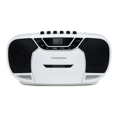
3
:
AEP,
G
Model
|
2
UK
Model
L
|
|
es
=
|
i
~~
l=
vu
Ref.
No.
x *
ad
ee
aoe
*
on
anya
O
oO!
A8
A8
Part
No.
Description
Remark
4-943-088-41
CASE
3-704-366-01
SCREW
(CASE) (M3X8)
3-346-265-31
HOLDER,
PC
BOARD
©
1-569-007-11
ADAPTER,
CONVERSION
2P(E)
A-2007-140-A
SYSTEM
CONTROL
BOARD,
COMPLETE
(WR545:US,
Canadian)
COMPLETE
(WR545
:
AEP)
COMPLETE
(WR545
:G)
COMPLETE
(WR545:
UK,
AUS)
A-2007-141-A
SYSTEM
CONTROL
BOARD,
A-2007-142-A
SYSTEM
CONTROL
BOARD,
A-2007-143-A
SYSTEM
CONTROL
BOARD,
A-2007-144-A
SYSTEM
CONTROL
BOARD,
COMPLETE
(WR545:E)
A-2007-145-A
SYSTEM
CONTROL
BOARD,
COMPLETE
(WR741)
1-765-216-11
WIRE
(FLAT TYPE)
(11
CORE)
3-703-244~-00
BUSHING(2104),
CORD
(AEP,
UK, G,
AUS)
3-703-571-11
BUSHING
(S)
(4516),
CORD
(US,
Canadian,
E)
1-551-188-XX
CORD,
POWER(E)
1-558-945-21
CORD,
POWER
(POLAR.
SPT-1)
(US,
Canadian)
1-575-651-21
CORD,
POWER
(AEP,
G)
Ref.
No.
A8
A8
14
15
16
AT701
AT701
ATT701
AYS701
Part
No.
1-696-586-11
1-696-845-11
4-949-235-01
3-909-660-01
3-909-660-11
3-909-660-21
3-909-660-31
3-909-660-51
4-308-840-11
4-956-370-12
X-4941-291-]
X-4941-292-1
X-3340-138-1
X-4941-228-1
3-704-515-01
1-450-837-51
1-450-838-51
1-450-839-21
[697s
155-11
Description
Remark
CORD,
POWER
(UK)
CORD,
POWER
(AUS)
HOOK
(US,
Canadian,
AEP,
E,
G)
PANEL,
BACK(WR545:US,
Canadian)
PANEL,
BACK
(WR545:
AEP,
G)
PANEL,
BACK
(WR545:UK,
AUS)
PANEL,
BACK(WR545:E)
PANEL,
BACK(WR741)
HOLDER,
WIRE
BAND,
PLUG
FIXED
(UK,
AUS)
FOOT
ASSY(F58175S)
(WR545
:US,
Canadian)
FOOT
ASSY
(F58175S)
(WR545:AEP,
UK,
E, G,
AUS)
FOOT
ASSY
(WR741)
FOOT
ASSY(WR741)
SCREW
(BV/RING)
TRANSFORMER,
POWER
(US,
Canadian)
TRANSFORMER,
POWER
(AEP,
UK,
G,
AUS)
TRANSFORMER,
POWER
(E)
SELECTOR,
POWER
VOLTAGE
(VOLTAGE)
(E)
6-2.
FRONT
PANEL
SECTION
AC:
POWER
SWITCH
BOARD
AD:
HEADPHONE
BOARD
AE:
PANEL
BOARD
53
52
Ref.No.
Part
No.
Description
Remark
Ref.No.
Part
No.
Description
Remark
51
X-3367-783-1
PANEL
ASSY,
FRONT
(WR545:US,
Canadian)
66
3-354-962-01
SPRING
(EJ
SAFTY
SPRING
R)
51
X~3367-786-1
PANEL
ASSY,
FRONT
(WR545:
AEP,
UK,
E,
G,
AUS)
67
3-909-658-01
BUTTON
(FR-M)
(WR545)
51
X~3367-787-1
PANEL
ASSY,
FRONT
(WR741)
67
3-909-658-11
BUTTON
(FR-M)
(WR741)
52
X-3367-785-1
LID
(B)
ASSY,
CASSETTE
68
3-909-659-01
BUTTON
(SR-M)
(WR545)
53
3-367-431-01
KNOB
(BAL)
68
3-909-659-11
BUTTON
(SR-M)
(WR741)
54
3-909-661-01
KNOB
(REC)
69
A-4325-163-A
HOLDER
(L)
ASSY,
CASSETTE
55
X-3367-784-1
LID
(A)
ASSY,
CASSETTE
(WR545)
*
70
3-354-953-01
LEVER
(LOCK
LEVER
L)
55
X-3368-171-1
LID
(A)
ASSY,
CASSETTE(WR741)
a
3-354-961-01
SPRING
(EJ
SAFTY
SPRING
L)
56
3-377-328-11
BUTTON
(EJECT)
1Z
3-354-955-01
LEVER
(EJ
SAFTY
LEVER
L)
57
3-377-330-01
BUTTON
(COUNTER)
73
3-354-959-01
SPRING
(LOADING
L),
TORSION
58
3~382-382-11
SPRING,
COMPRESSION
*
75
3-354-954-01
LEVER
(LOCK
LEVER
R)
59
3-354-932-01
BUTTON
(POWER)
76
3-354-957-01
JOINT
(LOCK
LEVER)
60
4-951-620-11
SCREW
(2.
6X10),
+BVTP
*
77
3-377-337-11
HOLDER
(FL)
61
A-4325-164-A
HOLDER
(R)
ASSY,
CASSETTE
78
1-765-214-11
WIRE
(FLAT
TYPE)
(7
CORE)
62
3-308-823-11
DETENT,
CASSETTE
79
1-765-217-11
WIRE
(FLAT
TYPE)
(37
CORE)
63
3-354-963-01
DAMPER
80
1-765-213-11
WIRE
(FLAT
TYPE)
(7
CORE)
64
3-354-960-01
SPRING
(LOADING
R),
TORSION
81
1-765-215-11
WIRE
(FLAT TYPE)
(7
CORE)
65
3~-354-956-01
LEVER
(EJ
SAFTY
LEVER
R)
VFD901
1-517-263-11
INDICATOR
TUBE,
FLUORESCENT

Other manuals for TC-WR545 Primary

3

This manual suits for next models

1

Other Sony Cassette Player manuals

Sony Walkman WM-EX631 User manual

Sony

Sony Walkman WM-EX631 User manual

Sony CFM-D1 User manual

Sony

Sony CFM-D1 User manual

Sony TC-WA7ESA - Dual Auto Reverse Cassette User manual

Sony

Sony TC-WA7ESA - Dual Auto Reverse Cassette User manual

Sony CFS-515S User manual

Sony

Sony CFS-515S User manual

Sony EV-S5000 User manual

Sony

Sony EV-S5000 User manual

Sony Pressman TCM-465V User manual

Sony

Sony Pressman TCM-465V User manual

Sony Walkman WM-EX2000 User manual

Sony

Sony Walkman WM-EX2000 User manual

Sony Walkman WM-EX651 User manual

Sony

Sony Walkman WM-EX651 User manual

Sony TC-WR10ES User manual

Sony

Sony TC-WR10ES User manual

Sony Pressman TCM-5000EV User manual

Sony

Sony Pressman TCM-5000EV User manual

Sony Walkman WM-FX241 User manual

Sony

Sony Walkman WM-FX241 User manual

Sony Walkman WM-EX527 User manual

Sony

Sony Walkman WM-EX527 User manual

Sony Walkman WM-EX372 User manual

Sony

Sony Walkman WM-EX372 User manual

Sony PVW-2650 User manual

Sony

Sony PVW-2650 User manual

Sony CFS-201 User manual

Sony

Sony CFS-201 User manual

Sony TXD-RE210 User manual

Sony

Sony TXD-RE210 User manual

Sony WM-EX368 User manual

Sony

Sony WM-EX368 User manual

Sony Walkman WM-EX9 User manual

Sony

Sony Walkman WM-EX9 User manual

Sony Walkman WM-FX161 User manual

Sony

Sony Walkman WM-FX161 User manual

Sony TCM-500DV User manual

Sony

Sony TCM-500DV User manual

Sony Walkman WM-GX654 User manual

Sony

Sony Walkman WM-GX654 User manual

Sony TC-K6000ES User manual

Sony

Sony TC-K6000ES User manual

Sony Walkman WM-EX552 User manual

Sony

Sony Walkman WM-EX552 User manual

Sony WALKMAN WM-GX822 User manual

Sony

Sony WALKMAN WM-GX822 User manual

Popular Cassette Player manuals by other brands

PENTRON HF-400 manual

PENTRON

PENTRON HF-400 manual

Philips DCC 170 operating instructions

Philips

Philips DCC 170 operating instructions

Denon DRM-555 Specifications

Denon

Denon DRM-555 Specifications

Harman Kardon TD292 owner's manual

Harman Kardon

Harman Kardon TD292 owner's manual

Hannlomax HX-323CD instruction manual

Hannlomax

Hannlomax HX-323CD instruction manual

Aiwa CSD-SL20 Service manual

Aiwa

Aiwa CSD-SL20 Service manual

Pioneer CT-F1250 operating instructions

Pioneer

Pioneer CT-F1250 operating instructions

Technics RS-BR465 operating instructions

Technics

Technics RS-BR465 operating instructions

Coby CVR-22 instruction manual

Coby

Coby CVR-22 instruction manual

Technics RS-B605 operating instructions

Technics

Technics RS-B605 operating instructions

Teac CX-400 Service manual

Teac

Teac CX-400 Service manual

Califone CAS1500 user manual

Califone

Califone CAS1500 user manual

Aiwa CS-P55 Service manual

Aiwa

Aiwa CS-P55 Service manual

Teac W-860R owner's manual

Teac

Teac W-860R owner's manual

Sanyo M-X920LU Service manual

Sanyo

Sanyo M-X920LU Service manual

Aiwa TP-VS530 Service manual

Aiwa

Aiwa TP-VS530 Service manual

Sanyo M7700L Service manual

Sanyo

Sanyo M7700L Service manual

Sanyo TRC-960C Service manual

Sanyo

Sanyo TRC-960C Service manual

manuals.online logo
manuals.online logoBrands
  • About & Mission
  • Contact us
  • Privacy Policy
  • Terms and Conditions

Copyright 2025 Manuals.Online. All Rights Reserved.