manuals.online logo
Brands
  1. Home
  2. •
  3. Brands
  4. •
  5. Sony
  6. •
  7. CD Player
  8. •
  9. Sony CDP-502ESII User manual

Sony CDP-502ESII User manual

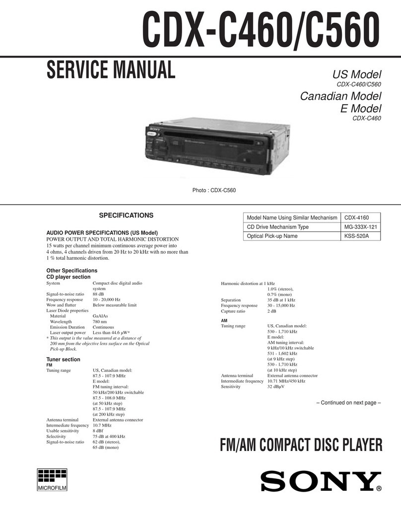
ERVICE
MANUAL
Photo:
CDP-650ESDII
Refer
to
RM-D302/D502
Service
Manual
issued
separately
for
information
of
the
remote
controller
supplied
with
this
set.
CDP-620ESII/650ESDII:
US
Model
Canadian
Model
CDP-502ESII/552ESDI:
AEP
Model
UK
Model
E
Model
SPECIFICATIONS
System
Compact
disc
digital
audio
system
Outputs
Line
outputs
Disc
Compact
disc
FIXED
(phono
jacks)
Laser
Semiconductor
laser
(A
=
780
nm)
Output
level
2
V
rms
(at
MSB)
Laser
output
Max.
0.4
mW
*
Load
impedance
over
10
kilohms
*
This
output
is
the
value
measured
at
a
distance
of
about
1.6
mm
from
the
objective
lens
surface
on
the
Optical
Pick-up
Block.
200
r.p.m.
to
500
r.p.m.
(CLV)
1.2-
1.4
misec.
Sony
Super
Strategy
Cross
Interleave
Reed
Solomon
Code
Spindle
speed
Scan
velocity
Errorcorrection
Number
of
channels
2
D-A
conversion
16-bit
linear
Frequency
responce
2
-
20,000
Hz
+
0.5
dB
Harmonic
distortion
Less
than
0.0025%
(1
kHz)
Dynamic
range
More
than
96
dB
Channel
separation
More
than
95
dB
(1
KHz)
Wow
and
flutter
Below
measurable
limit
SAFETY-RELATED
COMPONENT
WARNING!!
COMPONENTS
IDENTIFIED
BY
SHADING
AND
MARK
A\
ON
THE
SCHEMATIC
DIAGRAMS
AND
IN
THE
PARTS
LIST
ARE
CRITICAL
TO
SAFE
OPERATION.
REPLACE
THESE
COMPONENTS
WITH
SONY
PARTS
WHOSE
PART
NUMBERS
APPEAR
AS
SHOWN
IN
THIS
MANUAL
OR
IN
SUPPLEMENTS
PUBLISHED
BY
SONY.
|
MICROFILM
VARIABLE
(phone
jacks)
Max.
output
level
2
V
rms
(at
MSB)
Load
impedance
over
50
kilohms
Headphones
(stereo
phone
jack)
28
mW
at
32
ohms
CDP-552ESDII/650ESDII:
DIGITAL
OUT
(phono
jacks)
Max.
output
level
0.5
Vp-p
Load
impedance
75
ohms
—
Continued
on
page
2
—
ATTENTION
AU
COMPOSANT
AYANT
RAPPORT
A
LA
SECURITE!
LES
COMPOSANTS
IDENTIFIES
PAR
UNE
TRAME
ET
UNE
MARQUE
/\
SUR
LES
DIAGRAMMES
SCHE-
MATIQUES
ET
LA
LISTE
DES
PIECES
SONT
CRITIQUES
POUR
LA
SECURITE
DE
FONCTIONNEMENT.
NE
REM-
PLACER
CES
COMPOSANTS
QUE PAR
DES
PIECES
SONY
DONT
LES
NUMEROS
SONT
DONNES
DANS
CE
MANUEL
OU
DANS
LES
SUPPLEMENTS
PUBLIES
PAR
COMPACT
DISK
PLAYER
SONY.
AUD
CDP-502ESII/55
2ESDII/620ESII/650ESDII
Disc
Track
pitch
1.6
um
Sampling
frequency
44.1
kHz
Quantization
16
bit
linear
quantizing/channel
Modulation
system
EFM
Transfer
rate
2.03
Mbit/sec.
(before
modulation)
General
Power
requirements
US/Canadian
model:
120
V
AC,
60
Hz
AEP
model:
220
V
ac
(or
240
V
ac
adjustable
by
Sony
personnel),
50/60
Hz
UK
model:
240
V
ac
(or
220
V
ac
adjustable
by
Sony
personnel),
50
Hz
E
model:
110,
120,
220
or
240
V
adjustable,
50/60
Hz
Power
consumption
16W
CDP-502ESII/620ESII:
Approx.
430
x
85
x
335
mm
(w/h/d)
(17
x
33/,
x
131/,
inches)
including
projecting
parts
and
controls
CDP-552ESDII/650ESDO:
Approx.
430
x
85
x
365
mm
(w/h/d)
(17
x
34/5
x
143/,
inches)
including
projecting
parts
and
controls
Weight
CDP-502ESII/620ESI:
Approx.
8.5
kg
(18
Ibs,
12
02),
net
CDP-552ESDII/650ESDI:
Approx.
9.3
kg
(20
Ibs,
8
oz),
net
Dimensions
FEATURES
¢
High
performance
and
high
fidelity.
Direct
digital
signal
output
provides
for
the
highest
possible
sound
quality,
when
this
unit
is
connected
to
an
external
D/A
converter.
(CDP-552ESDII/650ESDII)
*
Feather-touch
function
buttons
for
direct
mode
change.
©
Linear
motor
for
quick
selection
search.
°
A
variety
of
playing
modes:
CONTINUE
mode,
PROGRAM
mode
and
SINGLE
mode.
¢
Index
function
for
quick
location
of
the
part
you
want.
¢
Repeat
function
for
one
selection,
the
whole
disc,
programmed
selections,
selections
with
random
order
or
a
particular
portion.
*
Auto
delay
function
allows
you
to
delay
the
playback
of
the
first
selection
2
seconds.
TABLE
OF
CONTENTS
Section
Title
Page
Specifications:
iio.
de
de
as
Ew
BE
1
B@atures
02.
¢
dish
Roads
Pee
nh
es
SS
2
Model
Identification
................4..
3
Safety
Check-Out
.......0...0.....0.04.
3
Protection
of
Eyes
from
Laser
Beam
During
Servicing...
2...
0.0...
eee
4
Servicing
Note
............
0.000002
eee
5
Caution
for
Electrostatic
Breakdown
........
6
Flow
Chart
of
BU-1C
(Base
Unit)
Troubleshooting...
............0000085
7
Function
of
Controls..............00004
9
Notes
on
Compact
Discs
................
11
SECTION
1
OUTLINE
1-1.
Circuit
Description
................
12
1-2.
Block
Diagram
...................
15
SECTION
2
DISASSEMBLY
.............
17
SECTION
3
ADJUSTMENTS
3-1.
Mechanical
Adjustment
.............
2
3-2.
Electrical
Adjustments..............
2
SECTION
4
DIAGRAMS
4-1.
BU-1C
(Base
Unit)
Section
Mounting
Diagram
................
25
4-2.
CDP-502ESI/620EST
Mounting
Diagram
................
28
4-3.
CDP-502ESH/620ES0
Schematic
Diagram
................
3)
4-4.
CDP-552ESDII/650ESDI
Mounting
Diagram
................
38
4-5.
CDP-552ESDII/650ESDII
Schematic
Diagram
................
43
4-6.
Power
Supply
Section
Mounting
Diagram
and
Schematic
Diagram
.............
4
SECTIONS
EXPLODED
VIEWS
AND
PARTS
LIST
..............
33
SECTION
6
ELECTRICAL
PARTS
LIST....
6!
CDP-502ESII/55
2ESDII/620ESII/650ESDII
MODEL
IDENTIFICATION
—
Specification
Labels
—
CDP-502ESII/620ESI:
US,
Canadian
model:
CDP-620ESI
AEP,
UK,
E
model:
CDP-502ESII
SONY:
MODEL
NO,
KS
COMPACT
DISK
PLAYER
WLLL
SERIAL
NO.
MADE
IN
JAPAN
US,
Canadian
model:
AC:
120
V~
60
Hz
16W
AEP
model:
AC: 220
V
~
50/60
Hz
16
W
UK
model:
AC:
240
V
~
50/60
Hz
16
W
E
model:
AC:
110,
120,
220,
240
V
~
50/60
Hz
16
W
CDP-552ESDII/650ESDH:
US,
Canadian
model:
CDP-650ESDII
AEP,
UK,
E
model:
CDP-552ESDI
SONY:
MODEL
NO.
RSS
COMPACT
DISK
PLAYER
WLLL
LLL
SERIAL
NO.
MADE
IN
JAPAN
US,
Canadian
model:
AC:
120
V
~60Hz
16W
AEP
model:
AC:
220
V
~
50/60
Hz
16
W
UK
model:
AC:
240
V
~
50/60
Hz
16
W
E
model:
AC:
110,
120,
220,
240
V
~
50/60
Hz
16
W
SAFETY
CHECK-OUT
(US
Model)
After
correcting
the
original
service
problem,
perform
the
following
safety
check
before
releasing
the
set
to
the
customer:
Check
the
antenna
terminals,
metal
trim,
‘‘metallized”’
knobs,
screws,
and
all
other
exposed
metal
parts
for
AC
leakage.
Check
leakage
as
described
below.
LEAKAGE
TEST
The
AC
leakage
from
any
exposed
metal
part
to
earth
ground
and
from
all
exposed
metal
parts
to
any
exposed
metal
part
having
a
return
to
chassis,
must
not
exceed
0.5mA
(500
microampers).
Leakage
current
can
be
measured
by
any
one
of
three
methods.
1.
A
commercial
leakage
tester,
such
as
the
Simpson
229
or
RCA
WT-540A.
Follow
the
manufacturers’
instructions
to
use
these
instru-
ments.
2.
<A
battery-operated
AC
milliammeter.
The
Data
Precision
245
digital
multimeter
is
suitable
for
this
job.
3.
Measuring
the
voltage
drop
across
a
resistor
by
means
of
a
VOM
or
battery-operated
AC
volt-
meter.
The
“limit”
indication
is
0.75
V,
so
analog
meters
must
have
an
accurate
low-
voltage
scale.
The
Simpson
250
and
Sanwa
SH-63Trd
are
examples
of
a
passive
VOM
that
is
suitable.
Nearly
all
battery
operated
digital
multimeters
that
have
a
2V
AC
range
are
suitable.
(See
Fig.
A)
To
Exposed
Metal
Parts
on
Set
AC
0.15
uF
S1.5k9
voltmeter
{0.75
V)
=
Earth
Ground
Fig.
A.
Using
an
AC
voltmeter
to
check
AC
leakage.
CDP-502ES/I/55
2ESDII/620ESII/650ESDII
PROTECTION
OF
EYES
FROM
LASER
BEAM
DURING
SERVICING
This
set
employs
a
laser.
Therefore,
be
sure
to
fol-
low
carefully
the
instructions
below
when
servicing.
WARNING
!!
WHEN
SERVICING,
DO
NOT
APPROACH
THE
LASER
EXIT
WITH
THE
EYE
TOO
CLOSELY.
!N
CASE
IT
IS
NECESSARY
TO
CONFIRM
LASER
BEAM
EMISSION,
BE
SURE
TO
OBSERVE
FROM
A
DISTANCE
OF
MORE
THAN
25
cm
FROM
THE
SURFACE
OF
THE
OBJECTIVE
LENS
ON
THE
OPTICAL
PICK-UP
BLOCK.
CAUTION:
The
use
of
optical
instrument
with
this
product
will
increase
eye
hazard.
CAUTION
Use
of
controls
or
adjustments
or
performance
of
procedures
other
than
those
specified
herein
may
result
in
hazardous
radiation
exposure.
SSS
SHORES
S
HB
e
Te
Here
re
resese
rere
1.
Laser
Diode
Properties
Material:
GaAlAs
Wavelength:
780
nm
Emission
Duration:
continuous
Laser
Output:
max.
0.4
mW*
e
e
e
e
*
This
output
is
the
value
measured
at
a
distance
of
about
1.6mm
from
the
objective
lens
surface
on
the
Optical
Pick-up
Block.
@
Classification:
Class
Mb
2.
During
service,
do
not
take
the
Optical
Pick-up
Block
apart,
and
do
not
adjust
the
APC
circuit.
If
there
is
a
breakdown
in
the
APC
circuit
(includ-
ing
laser
diode),
replace
the
entire
Optiocal
Pick-
up
Block
(including
APC
borad).
Oe
BESKYTTELSE
AF
@JNE
MOD
LASERSTRALING
UNDER
SERVICE
I
dette
apparat
anvendes
laserlys.
Derfor
skal
nedenstaende
instruktioner
naje
folges
under
service.
Folg
iovrigt
instruktionerne
i
servicemanualen.
ADVARSEL!!
Under
service
ma
gjnene
ikke
komme
nzr
objektiv-linsen
pa
den
optiske
pick-up
enhed.
|
tilfzelde
af
at
det
er
ngdvendigt
at
kontrollere
udsendelsen
af
laserlys,
skal
det
ske
i
en
afstand
af
mere
end
25cm
fra
den
optiske
pick-up.
LASER
ADVARSEL
MARKNING
Folgende
mzrkning
findes
indvendig
i
apparatet:
1.
Advarsel
Mzerkning
CAUTION
AND
INTERLOCKS
OEFEATED
ADVARSEL
:
:
INVISIBLE
LASER
RADIATION
WHEN
OPEN
AVOID
EXPOSURE
TO
BEAM.
USYNLIG
LASERSTRALING
VEO
ABNING
NAR
SIKKERHEDSAFBAYOERE
ER
UDE
AF
FUNKTION
UNOGA
UDSATTELSE
FOR
STRALING.
te
7
1.
Laser-didoe
data
@
Materiale:
GaAlAs
@
Belgelengde:
780
nm
@
Udstraling:
Kontinuerlig
@
Laseroutput:
Max.
0,4
mW*
*
Malt
i
1,6
mm
afstand
fra
overfladen
af
objektiv-
linsen
pa
den
optiske
pick-up
enhed.
@
Klassifikation:
Klasse
Mb.
2.
Adskil
aldrig
den
optiske
pick-up
enhed
under
service,
og
juster
ikke
APC
kredslebet
(Automatic
Power
Control).
Hvis
APC
kredslebet
(incl.
laser-
dioden)
bryder
ned,
skal
hele
den
optiske
pick-up
enhed
(incl.
APC
printkortet)
udskiftes.
RR
me
eee
meee
eee
eee
et
eee
VAROITUS:
Laite
sisaltaa,
laserdiodin,
joka
lahettia
(nakymatonta)
silmille
vaarallista
lasersateilya.
CDP-502ESII/55
2ES
DII/620ESII/650ESDII
—
SERVICING
NOTE
—
A
transit
lever
is
provided
at
the
bottom
of
the
unit
to
protect
the
NOTES
ON
LASER
DIODE
EMISSION
CHECK
The
laser
beam
on
this
model
is
concentrated
so
as
to
be
focused
on
the
disc
reflective
surface
by
the
objective
lens
in
the
optical
pick-up
block.
There-
fore,
when
checking
the
laser
diode
emission,
observe
more
than
25
cm
away
from
the
objective
lens.
LASER
DIODE
AND
FOCUS
SERCH
OPERA-
TION
CHECK
1.
Make
POWER
switch
on
with
no
disc
inserted
and
disc
table
closed.
2.
Confirm
that
the
following
operation
at
right
is
performed
while
observing
the
objective
lens.
@
Hold
down
optical
pick-up
block
and
chucking
arm
by
a
finger.
==
Es
chucking
arm
optical
pick-up
~
—
Se
>
—
C2)
Confirm
that
laser
beam
is
spread.
(3)
Up
and
down
motion
of
the
objective
lens.
(3
times)
optical
system
against
shock
during
transportation.
Before
starting
repairing,
make
following
procedures.
Screwdriver
Bottom
Slot
=
=
Screw
(red)
Transit
lever
1.
Loosen
the
screw
(red)
with
the
screwdriver.
2
__=Insert
the
screwdriver
into
the
slot
in
the
lever
and
move
it
in
the
direction
of
the
arrow
until
it
stops.
3
Tighten
the
screw.
NOTES
ON
IC
REPLACEMENT
@
When
replacing
IC401,
501,
first
clean
the
IC
head
and
the
inside
of
the
heat
sink
with
alcohol,
then
mount
the
heat
sink
and
fill
the
heat
sink
indented
portion
with
an
epoxy
type
adhesive*,
as
shown
in
the
illustration
below.
*
Epoxy
type
adhesive:
Sony
bond
SC1000
or
other
quick
drying
2
liquid
compound.
epoxy
adhesive
——
1C
:
l
protruding
|
section
i
>
Is
|
|
pas
heat
sink
CDP-502ESII/55
2ESDII/620ESII/650ESDII
—
CAUTION
FOR
ELECTROSTATIC
BREAKDOWN
—
NOTES
ON
HANDLING
THE
BASE
UNIT
(BU-1C)
The
laser
diode
in
the
optical
pick-up
block
may
1.
Place
a
conductive
sheet
on
the
workbench.
suffer
electrostatic
breakdown
because
of
the
poten-
(The
black
sheet
used
as
repair
parts
wrapping).
tial
difference
generated
by
the
charged
electrostatic
2.
Place
the
set
on
the
conductive
sheet.
so
that
the
load,
etc.
on
clothing
and
the
human
body.
The
printed
matter
below
is
included
in
the
repair
parts.
During
repair,
use
the
procedure
in
the
printed
chassis
touches
the
sheet.
(This
makes
it
the
same
potential
as
the
conductive
sheet).
3.
Place
your
hands
on
the
conductive
sheet.
(This
matter.
The
following
method
is
an
example
for
reference
makes
them
the
same
potential
as
the
sheet).
purposes:
4.
Remove
the
optical
pick-up
block.
5.
Perfrom
work
on
top
of
the
conductive
sheet.
Be
careful
that
clothing
does
not
touch
the
optical
pick-up
block.
Printed
Matter
Included
in
the
Repair
Parts
When
opening
or
repairing
a
BU-1C,
the
procedure
for
grounding
as
follows
is
required
to
prevent
damage
caused
by
static
electricity.
1.
Grounding
for
the
human
body.
Be
sure
to
put
on
a
wrist-strap
for
grounding
(with
impedance
lower
than
10°Q2)
whose
other
end
is
grounded
The
strap
works
to
drain
away
the
static
electricity
built-up
on
the
human
body.
2.
Grounding
for
the
work
table.
Be
sure
to
lay
on
the
table
a
cunductive
sheet
(with
impedance
lower
than
10°92)
such
as
sheet
of
copper
which
is
grounded.
3.
As
static
electricity
built-up
on
clothes
is
not
drained
away,
be
careful
not
to
let
your
clothes
touch
the
BU-IC.
Wrist-strap
for
grounding
transit
protective
cap
The
unit
BU-1C.
@)
Conductive
sheet
CDP-502ESII/55
2ESDII/620ESII/650ESDII
CDP-502ESII/55
2ESDII/620ESII/650ESDII
FLOW
CHART
OF
BU-1C
(BASE
UNIT)
TROUBLESHOOTING
®
Confirm
all
connectors
around
BU-1C
(base
unit)
are
secured
before
the
following
check.
[SERVO
BOARD]
POWER
ON
IS
OPTICAL
o
PICK-UP
SET
AT
SLED
MOTOR
DRIVE
CIRCUIT
INNERMOST
IS
—1.4
VOLTAGE
OUTPUT
AT
THE
EMITTERS
‘
CIRCUMFER-
OF
Q205
AND.Q206?
ENCE?
DO
NOT
OBSERVE
LASER
BEAM
|
NEAR
THE
OBJECTIVE
LENS.
CHECK
opera.
BE
SURE
TO
OBSERVE
MORE
Dee
miee
eco:
THAN
25
CM
AWAY
ee
DOES
LASER
|
De
AGe
EGR
NO
ARE
+B
(+5
V)
AND
—B
(—5
V)
VOLTAGES
|
SEE
ae
TION
APPLIED
TO
BU-1C
(BASE
UNIT)?
1
CHECK.
|
YES
@fis
THE
VOLTAGE
NO
|
OF
IC303
(ss
PJ
Pee
TERMINAL
@5)
+5
v?
)
4)
YES
FOCUS
COIL
DRIVE
CIRCUIT
|
DOES
FOC
@SEARCH
EpeRRTER
c
NG
1S
VOLTAGE
OUTPUT
APPLIED
TO
EMITTERS
|
NO
|
“SEE
PAGE
5
FOR
OF
Q201
AND
202?
+1
—--—---->.-
etal
Ske
gel
(THREE
CYCLE
search’
\—7\
7
\
OPERATION
IS
SHOWN.)
|
YES
|
|
©
|
-
|
<D0ES
DISC
MOTOR
NO
CHECK
FOK
SIGNAL.
2
|
<ROTATE?
IS
THE
VOLTAGE
OF
THE
BASE
OF
Q303
4.8
v?
|
|
Gee VES
1§
THE
VOLTAGE
|
OF
1C306
TERMINAL
—->+|
READ
TOC
INFORMATION
CHECK
OPERA.
TION
WITH
DISC
INSERTED.
CONFIRM
THAT
NO
<
Toc
IS
READ.
are
PAGE
8.
=
DETECTION
CIRCUIT
OPERATION
CHECK.
CONFIRM
THAT
THE
WAVEFORM
BELOW
IS
OBSERVED.
SEE
PAGE
12
FOR
CONFIRMING
PROCEDURE.
eae
=F
SCRATCH
WIDTH
YES
BU-1C
OPERATION
CHECK
IS
OVER.
@
-0.7
v?
YES
CHECK
RF
SIGNAL.
CONFIRM
THAT
THE
WAVEFORM
BELOW
IS
OBSERVED.
RF
SIGNAL
WAVEFORM.
(ay
|
|
|
|
|
|
ARR
|
OOO
OOK
A
4.4,9.0.0.0.0000.004,
1Vp-p
HERR
|
0.3V
|
|
1
I
THE
DIAMOND
SHAPE
(0)
IN
THE
CENTER
OF
THE
WAVEFORM
SHOULD
BE
CLEARLY
DISTINGUISHED.
NO
REPLAC
CHECK
BU-1C.
THE
SET.
6
(SPL)
BU-1C
(BASE
UNIT)
5
2
2
8]
4
3
(FOK)
(—5V)
(+5V)
(SD)
(FD)
(LD
ON)
CHECKING
TOC
INFORMATION
READING
If
TOC
information
is
read
correctly,
the
number
of
selections
on
the
disc
and
the
total
playing
time
will
be
displayed.
The
display
will
be
as
follows
for
YEDS-1.
i
fa
Ie
1
Ll
i
|
eee
eee
ieee
SECOND
TRACK
MINUTE
%
the
number
of
selections
\
total
playing
time
CDP-502ESII/55
2ESDII/620ESII/650ESDII
CDP-502ESII/55
2ES
DII/620ESII/650ESDII
FUNCTION
OF
CONTROLS
eon
DIGITAL
[1)
[12]
mains
CDP-552ESDII/650ESDI:
LINE
OUT
CDP-502ESI/620ESII:
[13]
(14) (15)
(16)
17]
(18)
(49)
(20)
(2a)
[pista
_ouT
|
|
ah
©,
i
Front
panel
1
2
|
=
~—
co
o
Ess
=
o
[11]
pry
=
Lad
=
w
=
=
[15]
=
-i]
=]
=
co
=
wo
POWER
switch
Disc
compartment
Place
a
compact
disc
here.
OPEN/CLOSE
button
Display
window
Direct
selection
buttons
Select
the
desired
selection
directly
by
number.
ii
PAUSE
button
and
indicator
Press
to
pause
during
play.
To
release
the
pause
mode,
press
it
again.
p&
PLAY
button
and
indicator
AMS
(Automatic Music
Sensor)
buttons
Press
to
search
for
the
desired
selection.
INDEX
buttons
Press
to
search
for
a
particular
index
number
to
begin
playback
at
that
point.
Manual
search
buttons
Press
to
search
for
the
desired
portion
of
the
selection.
TIMER
switch
Slide
to
play
back
when
using
the
timer
available
optionally.
HEADPHONES
jack
(stereo
phone
jack)
Remote
sensor
and
indicator
(for
remote
control)
Picks
up
the
infrared
transmitting
signal
from
the
supplied
remote
commander.
REPEAT
programming
buttons
Press
to
repeat
play.
There
are
five
types
of
repeat
play:
one
selection,
all
selections,
A
<>
B,
program
and
shuffle
repeat.
TIME
(elapsed
or
remaining
time)
button
Shows
the
elapsed
time,
the
remaining
time
on
both
the
selection
being
played
and
the
whole
disc.
AUTO
DELAY
button
Inserts
two
seconds
of
blank
space
before
the
beginning
of
each
selection.
SHUFFLE
PLAY
button
Press
to
play
selections
in
a
random
order.
CLEAR
button
Press
to
clear
the
programmed
selections.
CHECK
button
Press
to
check
the
order
of
the
programmed
selections.
nN
o
w
STOP
button
[21]
PLAY
MODE
buttons
PROGRAM
button:
Press
to
play
the
programmed
selections.
SINGLE
button:
Press
to
play
one
selection.
CONTINUE
buttuon:
Press
to
play
from
the
first
(or
desired)
selection
to
the
last
selection.
NR
[22]
LINE
OUT/
()
PHONE
LEVEL
(headphone
level)
control
Adjusts
the
output
levels
for
LINE
OUT
jacks
on
the
rear
panel
or
the
HEADPHONES
jack
on
the
front
panel.
Display
window
3}
DISC
indicator
Lights
up
when
the
disc
compartment
is
closed
with
a
disc
in
place
or
when
the
disc
compartment
is
opened.
iad
DX)
>
TRACK
indicator
Shows
the
track
number
of
the
selection
being
played.
[25]
PGM
(program)
indicator
Lights
up
while
programming
is
being
done
and
while
checking
the
programmed
order.
nN
6)
INDEX
indicator
Displays
the
index
number
of
the
selection
being
played.
RO
~
Music
calender
display
window
Displays
disc
selection
numbers
up
to
20
selections.
i)
8]
Time
counter
Shows
the
elapsed
time
the
selection
has
been
played.
nN
o
REPEAT
indicator
Lights
up
during
repeat
play.
w
0)
AUTO
DELAY
indicator
Lights
up
when
the
AUTO
DELAY
button
is
pressed.
[=]
[31]
SHUFFLE
PLAY
indicator
Lights
up
when
the
SHUFFLE
PLAY
button
is
pressed.
3]
OVER
indicator
Lights
up
when
a
disc
with
more
than
20
selections
is
inserted.
CDP-502ESII/55
2ESDII/620ESII/650ESDII
The
illustration
on
page 3
shows
the
model
available
in
European
countries.
33]
LINE
OUT
jacks
FIXED:
Output
level
is
constant.
VARIABLE:
Output
level
can
be
changed
with
the
LINE
OUT
contro!
and
supplied
remote
commander.
34)
DIGITAL
OUT
jack
Directly
outputs
the
digital
audio
and
subcode
data
read
from
the
disc.
Connect
to
the
DIGITAL
IN
jack
of
an
optional
DAS-702ES
D/A
converter
unit.
35|
DIGITAL
OUT
switch
Slide
to
select
the
output
signal
from
the
DIGITAL
OUT
jack.
ON:
for
audio
and
subcode
data
output
ON
(FOR
AUDIO
USE):
for
audio
data
output
only.
Set
to
this
position
when
listening
to
music
through
a
connected
D/A
converter
unit.
OFF:
for
no
digital
data
output.
Set
to
this
position
when
listening
to
music
through
the
LINE
OUT
jacks.
AC
power
cord
SUBCODE
OUT
connector
This
connector
is
provided
to
extend
the
utility
of
this
compact
disc
player
by
allowing
for
the
connection
of
optional
equipment
which
will
be
available
in
the
future.
NOTES
ON
COMPACT
DISCS
Handle
the
disc
by
its
edge,
and
to
keep
the
disc
clean,
do
not
touch
the
rainbow
colored
surface.
Not
this
way
Do
not
expose
the
disc
to
direct
sunlight
or
heat
sources
such
as
hot
air
ducts,
or
leave
it
in
a
car
parked
in
direct
sunlight
where
there
can
be
a
considerable
rise
in
the
temperature.
Before
playing,
clean
the
disc
with
the
cleaning
cloth.
Wipe
the
disc
from
the
center
out.
Do
not
use
solvents
such
as
benzine,
thinner,
commercially
available
cleaners
or
anti-static
spray
intended
for
analog
discs.
After
playing,
store
the
disc
in
its
case.
CDP-5072ESII/55
2ESDII/620ESII/650ESDII
SECTION
1
OUTLINE
1-1.
CIRCUIT
DESCRIPTION
The
circuits
on
this
set
are
almost
the
same
as
those
on
CDP-502ES/620ES
and
CDP-552ESD/
650ESD,
which
is
already
on
the
market.
Therefore,
only
the
dropout
detection
circuit
and
mechanism
control
IC
(IC303),
which
change
base
unit
BU-1
to
BU-IC,
will
be
explained
here.
Refer
to
the
circuit
descriptions
in
the
CDP-502ES/620ES
and
CDP-
552ESD/650ESD
Service
Manual
for
other
portions.
1.
Dropout
Detection
Circuit
This
circuit
is
on
the
base
unit
BU-1C
RF
board.
If
there
are
any
bubbles
or
scratches
made
on
the
disc
when
it
is
produced,
these
will
adversely
affect
tracking,
or
focus
servo,
when
the
disc
is
played,
This
will
cause
mechanical
noise
to
be
generated
from
the
pick-up,
sound
skipping,
or
electrical
noise.
This
cir-
cuit
detects
these
bubbles
and
scratches,
and
the
out-
put
then
lowers
tracking
gain
or
focus
gain
loop
gain
to
prevent
these
problems.
{RF
BOARD)
‘“'-
Next
the
operation
will
be
explained.
Please
look
at
Fig.
1.
During
PLAY,
the
RF
signal
output
from
IC101
pin
G)
is
applied
to
D101
via
IC102-1
buffer.
This
RF
signal
is
envelope
wave
detected
at
D101.
Therefore,
during
normal
operation
(no
bubbles
or
scratches
on
the
disc)
D101
cathode
side
has
a
DC
component.
Bias
is
applied
via
D103
and
R115
so
that
IC102-2
comparator
output
is
low
at
this
time.
D102,
R114
and
C113
perform
the
role
of
adjusting
auto
bias
relative
to
RF
signal
level
fluctuation
and
also
act
as
a
smoothing
circuit
so
that
IC102-2
bias
dose
not
change
even
if
there
is
dropout.
Then,
if
there
are
bubbles
or
scratches,
the
RF
signal
is
cut,
and
IC102-2
pin
(2)
voltage
goes
lower
than
that
of
IC102-2
pin
@)
via
C111,
and
during
this
period,
comparator
output
IC102-2
pin
q@)
is
in-
verted
and
becomes
high.
This
signal
switches
IC203
switch,
and
tracking
gain
and
focus
gain
loop
gain
are
lowered.
IMAIN
BOARD)
10101
CX20109
1€102-1
BUFFER
TP102
wD
8103
10%
\——
Dropout
Detection
Circuit
+5
1€102-2
COMPARATOR
10201
CX20108
ero
HD14053BFP
GAIN
DOWN
SWITCH
Connect
to
@
side
at
‘’L’’.
Connect
to
O
side
at
‘’H”’.
Fig.
1
Dropout
Detection
Circuit
and
Gain
Down
Switch
Circuit
@
Ic102
@
(RF
signal)
@
Ic102
(2)
@
Ic102
@G)
©
D209
cathode
orn
afeerioh)
circuit
output
dropout
width
scratch
(scratch
width)
Fig.
2
Waveform
when
Dropout
is
Detected
(Measured
on
YEDS-1
disc
with
tape
of
about
1
mm
width
stuck
on
as
in
Fig.
3)
CDP-502ESII/55
2ESDII/620ESII/650ESDII
@
Dropout
Detection
Circuit
Operation
Check
1.
Stick
black
or
red
tape
(about
1
mm
wide)
onto
_-
disc
the
disc
as
sown
in
Fig.
3.
(This
is
to
get
the
drop-
out
detection
circuit
output
pulse.)
Do
not
stick
it
on
the
part
where
the
TOC
is
recorded,
however.
2.
Play
the
disc
prepared
in
step
1.
3.
Confirm
that
a
waveform
as
shown
in
Fig.2
@
is
on
main
board
D209
cathode
side.
normal
if
this
pulse
appears.
2.
Mechanism
Control
IC
(1C303)
The
mechanism
control
IC
(IC303)
uses
the
DATA
pin,
CLOCK
pin
and
LATCH
pin
to
instruct
IC201
(servo
IC
CX20108)
and
I1C307
(digital
processing/
CLV
servo
IC
CX23035),
and
also
has
TOC
data
and
Q
data
memorized,
which
it
uses
in
performing
direct
search,
etc.
Pin
Functions
Pin
Name
A
MUTE
COPY
ROM
OSCO
OSCI
Operation
is
Avoid
the
TOC
area,
and
stick
on
black
or
red
tape
of
about
71
mm
width.
Fig.
3
Tape
Location
Function
Audio
signal
muting
control
output.
‘‘H’’
during
muting.
Signal
output
pin
for
CD
copy
inhibit
to
IC310.
‘“‘L’’
for
copy
inhibit.
Disc
identification
signal
output.
Normally
“‘L’’.
*“‘H”
for
CD
ROM
disc.
Clock
pin.
Clock
pin.
RESET
Reset
input
pin.
Goes
“‘H”’
in
about
1.5
seconds
after
power
ON.
TEST
LSI
test
pin.
Not
used.
SCOR
SUB
Q
sync
signal
input
pin.
ADJ
IN IN
SW
When
this
pin
goes
“‘L’’,
IC303
detects
servo
or
other
abnormalities
and
disc
load
out
is
not
performed.
Used
for
servo
and
PLL
adjust-
ment.
Also,
direct
search
is
not
performed,
and
access
can
only
be
done
by
conventional
track
jump.
Input
pin
which
detects
that
the
disc
table
is
closed.
‘“‘L”
for
CLOSE.
IN
OUT
SW
IN
+
FOK
Input
pin
which
detects
that
the
disc
table
is
open.
‘‘L’’
for
OPEN.
Focus
OK
signal
input
pin.
IN
WFCK
IN
WFCK
(Write
Frame
Clock)
input
pin.
GFS
Guarded
Frame
Sync
input
pin.
‘‘H’’
is
input
when
disc
data
can
be
read
normally.
SUB
Q
SUB
Q
signal
(selection
address,
emphasis
data,
etc.)
input
pin.
GND
Ground
pin.
NC
Not
used.
SENSE
Input
pin
for
IC201,
IC307
SENS
output.
Q
CHECK
Inputs
CRC
results
of
SUB
Q
output
from
IC307.
Na
hE
el
CDP-502ESII/55
2ESDII/620ESII/650ESDII
a
OUT
Latch
output
pin
for
serial
data
to
IC201,
IC307.
21
OUT
DIRECT
Output
pin
to
IC201
during
1
track
jump.
Normally
“‘H’’.
Reverses
track
jump
pulse
direction
at
““L’”’,
When
‘‘H”
again,
set
to
normal
tracking
mode.
Outputs
““L”
for
a
set
time
by
detection
of
TZC
(Tracking
Zero
Cross)
rise
and
fall.
OUT
Output
pin
for
serial
data
to
IC201,
IC307.
Output
pin
for
serial
data
transmission
clock
to
IC201,
1C307.
Output
pin
which
controls
sled
motor
gain.
Normally
‘‘H’’.
“L”
during
access.
Input
pin
which
detects
optical
block
at
innermost
circumference.
cae,
aes
OV
shift
to
inside
Reaches
innermost
circumference.
Detected
oy
going
from
‘“‘L”
to
“H”’.
Not
used.
Normally
‘“‘H’’.
Trigger
output
pin
for
data
sent
to
IC801.
IC801
M
REQ
signal
acknowledge
signal
output
pin.
IC801
M
REQ
signal
input
pin.
Not
used.
IN/OUT
CMDO
—
CMD3
Data
input/output
with
IC801.
Output
pin
which
controls
laser
diode
ON/OFF.
LOAD
IN
Output
pin
which
drives
loading
motor
to
close
side.
LOAD
OUT
Output
pin
which
drives
loading
motor
to
open
side.
EPS
Output
pin
which
detects
disc
emphasis
and
switches
emphasis
ON/OFF.
VDD
Power
supply
pin
(5
V)
REC
MUTE
Synchro
REC
MUTE
signal
output
pin.
Not
used.
PAUSE
Synchro
PAUSE
release
signal
output
pin.
Not
used.
REC
M
Synchro
REC
signal
input
pin.
Not
used.
NC
Not
used.
D
MUTE
Digital
signal
muting
control
output
pin.
“H”
for
muting.
CDP-502ESII/55
2ESDII/620ESII/650ESDII
CDP-502ESII/552ESDII/620ESII/650ESDII
1-2.
BLOCK
DIAGRAM
SIRIAL
/
DIGITAL
SIGNAL
PROCESSOR
DIGITAL
FILTER
PARALLEL
7CLV
SERVO
1C309
BUFFER
CONVERTER
D/A
DISCHARGE
é307
(4)
COCK
Q3l2
Ae
1C450
CONVERTER
0401
5
DE-EMPHASIS
\
ha
BU-IC
(BASE
UNIT)
(2)
Lack
oara®
pe
Oe
O—Oomts_
1
Tt
me
—-—
ee
Orr
err
a
ere
Terre
ere
re
re
errr
errr
err err
er
7
(6)
WCLK
1C405
1
20
©
3!
|
BCLK
us
2
OPTICAL
PICK-UP
BLOCK
2)
FXO
40
|
-
|
(7)
OATA
BCLK
@O)
1C401
PASSrINER
RV400
RF
AMP/
SIGNAL
PROCESSOR
WCLK
(21)
InTEGRATER
[LOW
L
PHONE
LEVEL!
LINE
OUT
I
+5V
1C101
|
T
SWITCHING
(C402
-
404
6
<2
CRCF
LRCK
Q2)
400,402
VARIABLE
|
DETECTOR
|
WFCK
°
1
I
|
for}
hale
S
ae
|
ca
Gro!
|
+
=<
SCOR
4
|_|
|
(6)
P02
|
EXCK
\
j
x30!
lala
en
r
ptt
SUBQ
16.934
MHz
pr
zs
!
|
;
|
\
[ie
|
Deere
eto
ee
Shy
Se
Wo)
©
sper
ney
4
r
+5V
Ryo)
|
A
zs)
7
|
G6)
©,
Q306
C315
;
(EMPHASIS)
HEADPHONE
AMP
(2)
DATA
EXCK
—_BXTAL
S\
RESET
1
|
1c452
|
GF
©
DI
CH
aw;
$301
f
$f
R-CH
J401
ae
DAIO(LRCK)
OFF
—
w
23
S
|
@t
DI-De
_AD—AIO
1
Cr)
ac
SWITCH
+
138
SSE5R
ea
|
pl
[ReaDPHONES]
I
5)
D3
9)
>
ON
1
Fa
CHAYH
RELAY
RY400
|
|
rene
ee
Sa
eee,
nes
(For
aun
|
DRIVE
=
-l2V
(MUTE)
i
26)
D2
RSET
(18)
b
|\
Use
|
j
|
OETECTION
ce
t
je
CRC
$
;
LASER
DIODE
|
CIRCUIT
|
3)
05 ON
!
=
vonee
Lb
ic102
i
|
22)
06
f
i \
|
®)
|
AAR
i
(20)
07
1C310
x)
DRIVER
~
e
1
w
DIGITAL
AUDIO
DATA
C313,
|
|
1
ne
a
\
I
RACS
—
RAWE
3
2oss
S
Bs
!
MODULATION
/
TRANSMISSION
|
!
|
()
LASER
ON
|
2
oe
bis.
5.81
402
|
}
CIRCUIT
|
Eee
ee
COP-852ES00
/650ESDD
Tee
4
1
ar,
peer
|
Nadu
ce
5
cs
cee
|
|
7
\
|
|
en
ee
5
!
COP-502ES
I
/
620EST
2
i
|
1C250
J
|
DISC_
MOTOR
a
MOTOR
DRIVE
,
|
LISI
DRIVE
|
|
civ
servo
+5V
ve
I
DISC
MOTOR
CONTROL
————————
phon
<
EPS
>
<<
VOL
UP
VR
|
L152
C15!
|
1€305,
306
axssub
oy
Belen
QI51
—
154
\
gSeee
L301
22/301
JK
VoL
ow
|
So
Ble
am
BE
<
MUTE
>
D302
{>
(3827)
(S834)
(S838)
|
AKA
Fe
930
ae
assy)
(assy)
(assy)
peor
_p8oz
|
peepee
eae
at
Pees
eee
eg
Ziex
A
|
SWITCH
INVERTER
PROGRAM]
[
SINGLE]
[CONTINUE
][PLAY
]
[PAUSE
&
|
]
|
ols
1C305
us
|
YY
2
5
|
\
vco
22
|
a
|
ee
a
|
65)
<
Qint
FLOURESCENT
|
|
D
MUTE
@4)
D
MUTE
|<
SACK
INDICATOR
TUBE
(2-60)
(3)
suB
Q
(15)
SUB
Q
\~<
MREQ
FLD8OI
|
|
Tz
FE
@
CHECK
(CRCF)(19)
CRCF
MIRR
C11)
IZ
wk
WFCK
(13)
WFCK
—~<
CMD
0-3
|
Ese
Ze
scor(8)
SCOR
FOCUS
COIL
DRIVE
FOCUS
/
TRACKING
/SLED
ao
sig
FLD
DRIVE
|
y
201,
202
QFE
o
Be
Rom
(3)
ROM
pees
801-806
!
|
G201,
SERVO
copy
(2)
copy
—~<
ouT
Sw
|
2-AXIS
!
iC
201
ea
EPS(é)
EPS
a
DEVICE
|
\
TACHI
OE
DANE
GTA
0
sence
(S-=—_—_|
|
AMute
(1)
|
Me
G
aie?
‘
|
.
xuT
(Carcnn(g)
@
TQ
Q
INT
US
oe
KIN
K
SACK SACK
399
cat”
PY
ca
Scam
Sam
GEES
©
beat
eee
KEY
MATAR
:
| |
mee
6)
$801-
821
ai
823,825
,827
398
cmp
G-3
»>—*+#—
fy
|
|
MECHANISM
re
4
829-834
(H)
pc0
|
G
Sch
aie
A
CONTROL
636-
846,850
(REMOTE SENSOR)
es
=
\
7
1
202
ay
E
1¢303
TSW
»>—~
\&
switch
—/
!
ee
1
wri
ma
ae
1
209
VOL
OW
{
we
3.
|
9210
(Fy
G4)
SED
wow(o)
Ls]
of
COL
pS.
\
SS)
J,
—>
|
'
UY
a
™
|
14
LT
SLED
GAIN
_/
s|
$652
REMOTE
CONTROL
toy
SWITCH
LOAD
OUT DET
pais
i
!
25)
SLED
$
ae,
OFF
RESET
+
t
1
sesi
;
4
Hr
)
Loa
ia
bee
4
396,397
1c
803
|
SENSOR
Ss
1
!
OFF
ON
400
kHz
COIL
“Ny
\
\C202
9304
t
OFF
:
WHEN’
RESET
y
\—
uw
iw
oer
|
2%
LOADING
G6)
oN
DISCS
TABLE,
+
<
RESET
>
+
1c315
|
fl
MOTOR
DRIVE
|]
nue
;
902,903
ee
eee
ee
301,302
67)
‘So
ENDED
+10V
Lone
osc
0
RESET
MOTOR
DRIVE
(4)
©
PN
$654
5
o
CHUCKING
©
hme,
+5V<
$201
M651
.
z
CHUCKING
@)
+
:
RESET
-
POWER
OFF
ESET
>—
lov
<
ON
:
WHEN
FLUORESCENT
INDICATOR
TUBE
2
oy
DISC
TABLE
FILAMENT
AC
IN
1S
‘CLOSED
65!
$653
M652
SWITCH
MOTOR
SELECT
S|
S
LOADING
(“)
CHUCKING
MOTOR
eal
—
+12v
;
LOADING
MOTOR
+6V
IC910,
911,
-5V
IC912,
920
lav
—14v
9920-923,
9930-933
=
5S
<1
6-=
CDP-502ESII/552ESDII/620ESII/650ESDII
|
SECTION
2
DISASSEMBLY
FRONT
PANEL
AND
TOP
PLATE
CHUCKING
MOTOR
(M651)
Note:
Follow
the
disassembly
procedure
in
the
numerical
order
given.
0
B3x6
as
en
ae
E:
8
@
top
plate
PS3x
5
Giese
y
IN
SW
board
eene
motor
o-
@
gear
(A)
L.C.
SW
board
DISPLAY
BOARD,
KEYBOARD
SW
BOARD,
OPEN
SW
BOARD
@
—
QO:
DISPLAY
BOARD,
KEYBOARD
SW
BOARD
{i]
:
OPEN
SW
BOARD
BV3
x 6
(5
pes.)
retainer
(A)
(3
pes.)
pes.
@
8TP2.6
x
8
(2
pcs.)
OQ
PTP2.6
x
6
(3
pes.)
ROPE
STRINGING
POWER
SW
BOARD
retainer
(B)
pulley
(B)
e
PTP26
x
8
(3
pes.)
e
BVTT3x6
power
switch
bracket
CNJ202
‘
8
CNJ203
power
SW
board
@
BVTT3
x
6
(2
pcs.)
Sa
knob
joint
(B)
|
OBVTT3
x6
(2
pcs.)
power
switch
lever
e
Turn
twice
around
pulley
(C).
@
Set
the
rope
to
rope
bracket.
CDP-502ESII/55
2ESDII/620ESII/650ESDII
LOADING
MOTOR
(M652),
FF
BELT,
DRIVE
BELT,
LOAD
OUT
SW
BOARD
@
82.6x
3
Ce
CNP602
Le
Zoe
[estes
(to
load
in
sw
board)
“e=key
'le
2
ZZ
loading
CA.
motor
{to
L/C
sw
board)
'
(M652)
Pere
©
rive
belt
(to
main
board)
re
tes
loading
motor
board
BOTTOM
PLATE
Remove
bottom
plate
by
taking
out
7
screws
(BV3
x
8).
és
is
possible
to
check
main
board
from
conductor
ey
®
n
\
\
S
“\
BASE
UNIT
(BU-1C)
basilar
B3x20
_,B3x
20
(pein
Roere!
insulator
@f
fee
j
CNJ102
pole
insulator
pole
(main
board)
ea
Pa
B3x20
Ss
hea
s)
seus
i
insulator
pole
compression
spring
spacer
Ye"
‘cae
(insulator
C}
laa
spacer
compression
spring
(insulator
B)
CNJ151
(main
board)
compression
spring
™N
(insulator
A)
CNJ103
Note
(1):
When
replacing
BU-1C,
refer
to
“NOTES
ON
HANDLING
BASE UNIT
(BU-1C)”
on
page
6
to
prevent
damage
caused
by
static
electricity.
Note
(2):
Each
compression
spring
(insulator)
differs
in
size
and
turns.
When
installing
it,
refer
to
the
following
list.
silver
gold
black
compression
spring
(insulator)
Note
(3):
RF
board
is
included
in
BU-1C
and
can
not
A
B
Cc
be
replaced
in
itself.
CDP-502ESII/55
2ESDII/620ESII/650ESDII
BASE
UNIT
(BU-1C)
(See
page
19.)
OPTICAL
PICK-UP
BLOCK
(4)
Pull
out
frexible
Su
C3)
Unlock
connector
with
blade
screwdriver,
Refer
to
“NOTES
ON
HANDLING
BASE
UNIT
(BU-1C)”
on
page
6
to
prevent
damage
caused
by
static
electricity.
Open
lid
of
lead
retainer
(B)
and
take
out
lead
wires.
Q
Unsolder
the
lead
wires
of
sensor
coil
(SE51).
©
Unsolder
the
lead
wires
of
sled
coil
(M53).
=
Start
to
rotate.
082.65
@
Open
lid
of
lead
retainer
(A)
and
take
out
lead
wires.
OTA,
P2.6x
8
optical
pick-up
block
CDP-502ESII/55
2ESDII/620ESII/650ESDII
SLED
COIL
(M53),
SENSOR
COIL
(SE51)
©,
@::
sensor
coil
(SE51}
O~6@
:
sled
coil
(M53)
Q
sensor
coil
(SE51)
Q@evrr26x8
@
sled
coil
(M53)
FLEXIBLE
BOARD
Unsolder
@
marked
portion.
(total
three)
!
M53
Start
to
rotate.
optical
pick-up
block
Note:
Be
sure
not
to
remove
the
screws.
The
screws
fix
the
detector.
Therefore,
if
the
screws
are
removed
or
loosened,
the
detector
moves
and
cannot
receive
the
jaser
beam.
Unsolder
@
marked
portion.
(total
four)
Unsolder
@
marked
portion.
(total
seven}
iN
aca
ci
a:
hs
ee
i
CDP-502ESII/55
2ESDII/620ESII/650ESDII
SECTION
3
ADJUSTMENTS
3-1.
MECHANICAL
ADJUSTMENT
CHUCKING
ARM
HEIGHT
ADJUSTMENT
Adjust
the
height
of
portion
@)
with
disc
insert-
ed
and
disc
table
closed.
Repeat
loading
and
confirm
that
chucking
arm
does
not
touch
disc
pulley.
adjustment
screw
pulley
press
pulley
chucking
arm
dise
(a)
about
1
mm
(Same
height
as
a
disc}
3-2.
ELECTRICAL
ADJUSTMENTS
1.
2:
Perform
adjustments
in
the
order
given.
Use
YEDS-1
disc
(3-703-696-01)
unless
otherwise
indicated.
.
Use
the
oscilloscope
with
more
than
10
MQ
im-
pedance.
Adjustment
Mode
1.
Connect
servo
board
test
point
AF
and
ground.
This
is
to
prevent
the
disc
table
from
opening
even
though
pits
are
not
read,
by
making
micro-
computer
IC303
pin
9)
low.
.
Turn
POWER
switch
on.
(To
reset
microcomputer.)
After
adjustment,
remove
the
lead
wire
connecting
test
points
AF
and
ground.
Adjustment
Location:
servo
board
test
point
AF
(Connect
this
test
point
to
ground.)
CDP-502ESII/55
2ESDII/620ESII/650ESDII
CDP-502ESII/55
2ESDII/620ESII/650ESDII
RF
PLL
Adjustment
Procedure:
VTVM
(DC
range)
a
servo
geese
TPPLL
Oo
PLL
O————O
a
counter
servo
aire
pea
—
.
Turn
POWER
switch
ON
(stop
mode).
TP
PLCK
¢
PLCK
O———_O
.
Remove
connector
CNJ308.
.
Put
set
into
adjustment
mode.
(See
page
22.)
.
Connect
VTVM
to
servo
board
test
point
TP
PLL.
.
Adjust
main
board
RV301
so
that
reading
on
VTVM
is
0
V
+50
mV.
.
Connect
the
frequency
counter
to
servo
board
test
point
TP
PLCK.
.
Adjust
servo
board
L301
so
that
the
reading
on
frequency
counter
is
4.4018
MHz
+20
kHz.
.
Reconnect
lead
wires
connected
in
adjustment
mode
and
connect
the
connector
CNJ308.
9.
Put
disc
(YEDS-1)
in
and
press
>
PLAY
button.
.
Confirm
that
reading
on
frequency
counter
is
4.3218
MHz.
Adjustment
Location:
servo
board
TP
PLCK
—
z
L301
0
TP
PLL
1C€307
10305
f4
5
aa
Focus/Tracking
Gain
Adjustment
A
frequency
responce
analyzer
is
necessary
in
order
to
perform
this
adjustment
exactly.
However,
this
gain
has
a
margin,
so
even
if
it
is
slightly
off,
there
is
no
problem.
Therefore,
do
not
perform
this
adjustment.
Focus/tracking
gain
determines
the
pick-up
follow-
up
(vertical
and
horizontal)
relative
to
mechanical
noise
and
mechanical
shock
when
the
2-axis
device
operate,
However,
as
these
reciprocate,
the
adjustment
is
at
the
point
where
both
are
satisfied.
@
When
gain
is
raised,
the
noise
when
the
2-axis
device
operates
increases.
@
When
gain
is
lowered,
mechanical
shock
and
skipping
occurs
more
easily.
@
When
gain
adjustment
is
off,
the
symptoms
below
appear.
e
Music
does
not
start
and
low
bP
buttons
pressed.)
ed
disc
continues
to
rotate
for
STOP
>DPLAY
or
@
Disc
table
opens
shortly
lower
high
after
STOP>DPLAY.
:
e
Sound
is
interrupted
dur-
ing
PLAY.
Or
time
count-
er
display
stops
progress-
ing.
e
The
time
until
music
starts
becomes
longer
for
STOP
->
DPLAY
or
automatic
low
or
high
selection
(<4.
PPI
buttons
pressed.)
(Normally
takes
about
1
seconds.)
automatic
selection.
(Ke
e
More
noise
during
2-axis
high
high
device
operation.
The
following
is
a
simple
adjustment
method.
—
Primary
Adjustment
—
Note:
Since
exact
adjustment
cannot
be
performed,
remem-
ber
the
positions
of
the
controls
before
performing
the
adjustment.
If
the
positions
after
the
primary
adjust-
ment
are
only
a
little
different,
return
the
controls
to
the
original
position.
oscilloscope
(DC
range)
Procedure:
.
servo
board
Je
hin,
TP
FE
O——,—————0
+
i
Ue
TP
TEO-
-
1.
Keep
the
set
horizontal.
If
the
set
is
not
horizontal,
this
adjustment
cannot
be
performed
due
to
the
gravity
against
the
2
axis
device.
2.
Put
set
in
adjustment
mode.
(See
page
23.)
3.:
Insert
disc
(YEDS-1)
and
press
>
PLAY
button.
4.
Connect
oscillcscope
to
servo
board
TP
FE.
5.
Adjustment
RV201
so
that
the
waveform
is
as
shown
in
the
figure
below.
(focus
gain
adjustment)
@
Incorrent
Examples
(DC
level
changes
more
than
on
adjusted
waveform)
low
focus
gain
I——-O
V
high
focus
gain
VOLT/DIV:
TIME/DIV:
2mS
VOLT/DIV:
100mV
TIME/DIV:
2mS
1700mV
VOLT/DIV:
100
mv
TIME/DIV:
2mS
CIRCUIT
BO
6.
Connect
oscilloscope
to
main
board
TP
TE.
po
7.
Adjust
RV202
so
that
the
waveform
is
as
shown
in
: ;
:
;
load
out
S|
the
figure
below.
(tracking
gain
adjustment)
VOLT/DIvV:
1V
TIME/DIV:
2mS
a
Ov
OS
@
Incorrect
Examples
(fundamental
wave
appears)
low
trackin
in
ae
headphone
jack
bd
VOLT/DIV:
1V
TIME/DIV:
2mS
open
S|
—ov
d
high
tracking
gain
(higher
fundamental
wave
than
for
low
gain)
BSL
VOLT/DIV:
1V
TIME/DIV:
2mS
to
Adjustment
Location:
servo
board
/
RV202
Rv201
(
aan
(
focus
)
low
high
gain
gain
gain
gain
SOESDII
§CDP-502ESII/55
2ESDII/620ESII/650ESDII
The
following
is
a
simple
adjustment
method.
ary
in
—
Primary
Adjustment
—
7
rer
Note:
Since
exact
adjustment
cannot
be
performed,
remem-
if
it
is
“ae
p
ber
the
positions
of
the
controls
before
performing
the
Jo
not
adjustment.
If
the
positions
after
the
primary
adjust-
ment
are
only
a
little
different,
return
the
controls
to
the
original
position.
follow-
oscilloscope
hanical
4
(DC
range)
qaiice
Procedure:
;
servo
board
C)
é
—————
nt
is
at
TP
FE
O<———_z—————_0
+
|
1a.
2-axis
!
TP
TEOm-
-7
*k
and
.
1.
Keep
the
set
horizontal.
If
the
set
is
not
horizontal,
this
adjustment
below
cannot
be
performed
due
to
the
gravity
against
the
2
axis
device.
.
Put
set
in
adjustment
mode.
(See
page
23.)
.
Insert
disc
(YEDS-1)
and
press
>
PLAY
button.
:
Connect
oscilloscope
to
servo
board
TP
FE.
vA
fF
WwW
WN
.
Adjustment
RV201
so
that
the
waveform
is
as
shown
in
the
figure
below.
(focus
gain
adjustment)
VOLT/DIV:
100mvV
TIME/DIV:
2mS
®
Incorrent
Examples
(DC
level
changes
more
than
on
adjusted
waveform)
low
focus
gain
VOLT/DIV:
100mvV
TIME/DIV:
2mS
I—-O
v
high
focus
gain
VOLT/DIV:
100
mv
TIME/DIV:
2mS
6.
Connect
oscilloscope
to
main
board
TP
TE.
7.
Adjust
RV202
so
that
the
waveform
is
as
shown
in
the
figure
below.
(tracking
gain
adjustment)
VOLT/DIV:
1V
TIME/DIV:
2mS
@
Incorrect
Examples
(fundamental
wave
appears)
low
tracking
gain
VOLT/DIV:
1V
TIME/DIV:
2mS
m—
OV
high
tracking
gain
(higher
fundamental
wave
than
for
low
gain)
VOLT/DIV:
1V
TIME/DIV:
2mS
—oOv
Adjustment
Location:
servo
board
°
°
RV202
RV201
(
mie)
(
focus
)
low
high
gain
gain
gain
gain
CDP-502ESI/I/55
2ESDII/620ESII/650ESDII
SECTION
4
DIAGRAMS
CIRCUIT
BOARDS
LOCATION
power
SW
board
A
load
out
SW
board
subcord
board
(CDP-502ESII/620ESI!)
output
board
(CDP-552ESDII
/650ESDII)
B
C
headphone
jack
board
audio
board
open
SW
board
servo
board
display
board
remote
control
motor
board
D
keyboard
SW
board
remote
control
VR
board
BU-1C
(base unit)
BSL
motor
board
flexible
board
E
RR,
RF
board
F
{
N
FLEXIBLE
BOA
to
servo
board
(CONDUCTOR
to
servo
board
BQ
servo
board
[By
to
servo
board
chucking
motor
board
in
SW
board
L/C
SW
board
4-1.
BU-1C
(BASE
UNIT)
SECTION
M
1
2
AN
sued
coll
fi]
{UNA
SQ
2
\\
——
Q
FINISH:
START
TO
ROTA
RD(1/4
ata
|
(8%
zs
ee
2.
e?
_:
LASER
DIODE
BLK,
SMGQAQ

This manual suits for next models

3

Other Sony CD Player manuals

Sony CDX-F5710 - Fm/am Compact Disc Player User manual

Sony

Sony CDX-F5710 - Fm/am Compact Disc Player User manual

Sony CFD-V5 - Cd Radio Cassette-corder User manual

Sony

Sony CFD-V5 - Cd Radio Cassette-corder User manual

Sony CD Walkman D-EG3 User manual

Sony

Sony CD Walkman D-EG3 User manual

Sony CDP-CE575 - Disc Carousel User manual

Sony

Sony CDP-CE575 - Disc Carousel User manual

Sony DVP-FX930 User manual

Sony

Sony DVP-FX930 User manual

Sony CDP-CX50 User manual

Sony

Sony CDP-CX50 User manual

Sony CDX-3000 Product guide

Sony

Sony CDX-3000 Product guide

Sony CFD-ZW705 - Cd Radio Cassette-corder User manual

Sony

Sony CFD-ZW705 - Cd Radio Cassette-corder User manual

Sony CFD-E90PS Operating Instructions  (primary... User manual

Sony

Sony CFD-E90PS Operating Instructions (primary... User manual

Sony D-NE520 - Atrac Cd Walkman Portable Player User manual

Sony

Sony D-NE520 - Atrac Cd Walkman Portable Player User manual

Sony Xplod CDX-737 User manual

Sony

Sony Xplod CDX-737 User manual

Sony CDP-C425 User manual

Sony

Sony CDP-C425 User manual

Sony CFD-S250 - Cd Radio Cassette-corder User manual

Sony

Sony CFD-S250 - Cd Radio Cassette-corder User manual

Sony WALKMAN D-CJ01 User manual

Sony

Sony WALKMAN D-CJ01 User manual

Sony CD Walkman D-FJ200 User manual

Sony

Sony CD Walkman D-FJ200 User manual

Sony CDP-XE210 User manual

Sony

Sony CDP-XE210 User manual

Sony CDP-C77ES - Es 5 Disc Cd Changer User manual

Sony

Sony CDP-C77ES - Es 5 Disc Cd Changer User manual

Sony Walkman MZ-NF610 User manual

Sony

Sony Walkman MZ-NF610 User manual

Sony CDP-CA8ES - 5 Disc Cd Changer User manual

Sony

Sony CDP-CA8ES - 5 Disc Cd Changer User manual

Sony CDX-R550 User manual

Sony

Sony CDX-R550 User manual

Sony CDP-C435 - Compact Disc Player User manual

Sony

Sony CDP-C435 - Compact Disc Player User manual

Sony MDP-605 User manual

Sony

Sony MDP-605 User manual

Sony CDX-L490EE User manual

Sony

Sony CDX-L490EE User manual

Sony D-NE800 User manual

Sony

Sony D-NE800 User manual

Popular CD Player manuals by other brands

Technics SL-PG470A Service manual

Technics

Technics SL-PG470A Service manual

Philips AZ 7565 Instructions for use

Philips

Philips AZ 7565 Instructions for use

Yamaha DV-C6480 - Progressive-Scan DVD Player owner's manual

Yamaha

Yamaha DV-C6480 - Progressive-Scan DVD Player owner's manual

McIntosh MCD 7007 owner's manual

McIntosh

McIntosh MCD 7007 owner's manual

XINDAK C06 instructions

XINDAK

XINDAK C06 instructions

Harman Kardon FL 8550 owner's manual

Harman Kardon

Harman Kardon FL 8550 owner's manual

Pioneer PD-73 Service manual

Pioneer

Pioneer PD-73 Service manual

Jensen CD-60W user manual

Jensen

Jensen CD-60W user manual

DVS Pronto4K Hardware guide

DVS

DVS Pronto4K Hardware guide

Sharp GX-CD30 Service manual

Sharp

Sharp GX-CD30 Service manual

Panasonic CQ-C7413U? CQ-C7113U operating instructions

Panasonic

Panasonic CQ-C7413U? CQ-C7113U operating instructions

Pioneer XDV-M8137ZT/UC Service manual

Pioneer

Pioneer XDV-M8137ZT/UC Service manual

Philips EXP3481/17 Specifications

Philips

Philips EXP3481/17 Specifications

Pioneer CDX-P616 Service manual

Pioneer

Pioneer CDX-P616 Service manual

Kenwood DPF-1030 Service manual

Kenwood

Kenwood DPF-1030 Service manual

Creek Audio CD50 operating instructions

Creek Audio

Creek Audio CD50 operating instructions

Philips AS650/21 manual

Philips

Philips AS650/21 manual

Mark Levinson ?37 operating manual

Mark Levinson

Mark Levinson ?37 operating manual

manuals.online logo
manuals.online logoBrands
  • About & Mission
  • Contact us
  • Privacy Policy
  • Terms and Conditions

Copyright 2025 Manuals.Online. All Rights Reserved.