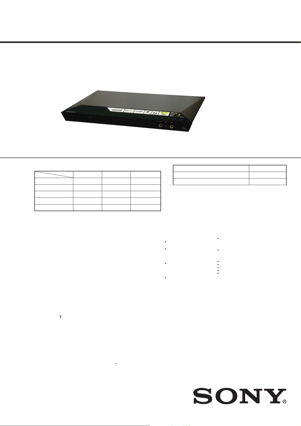
DAV-DZ350/DZ650/DZ950
2
1. SERVICING NOTES ............................................. 3
2. DISASSEMBLY
2-1. Disassembly Flow........................................................... 6
2-2. Top Cover (DJ) ............................................................... 6
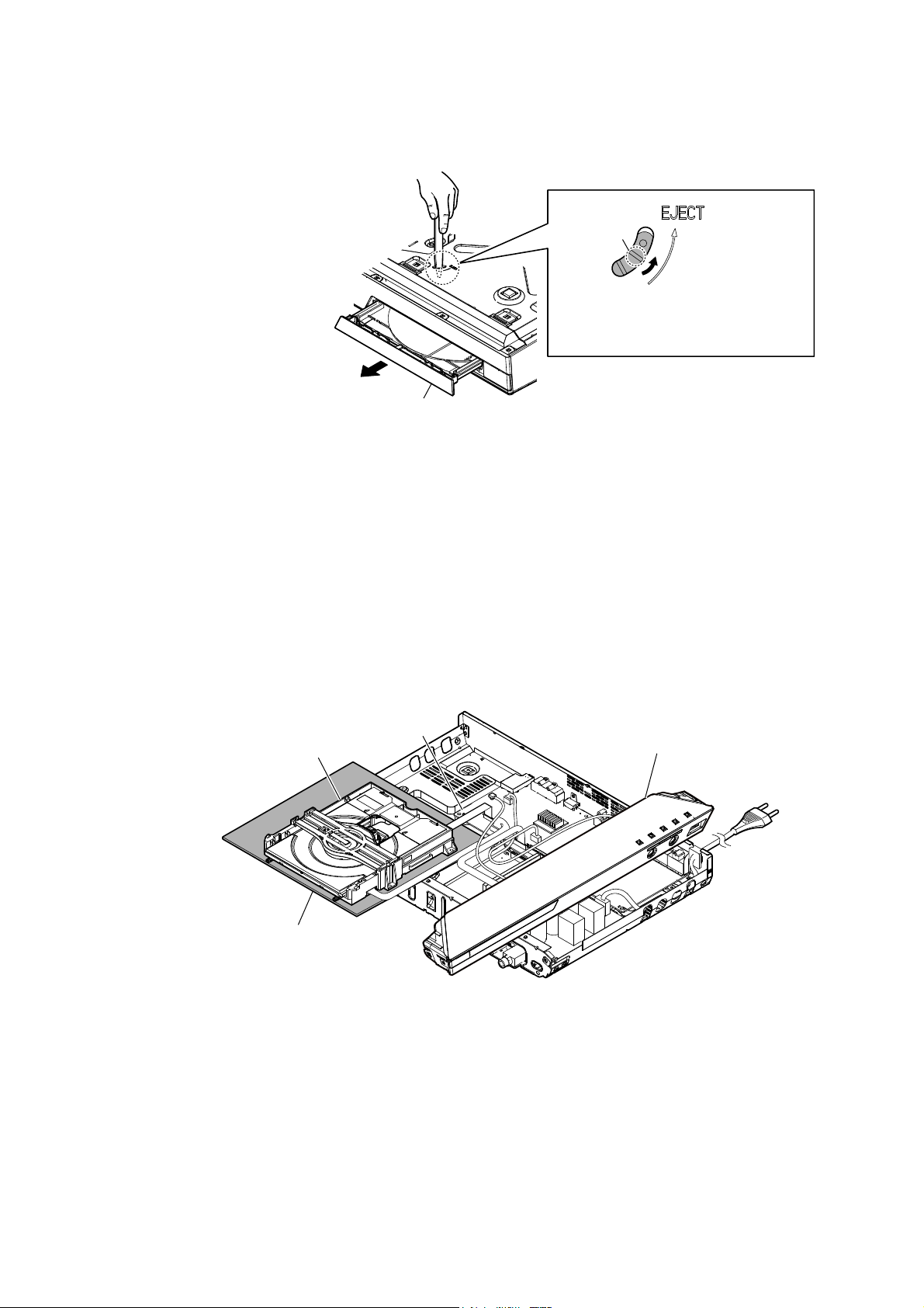
2-3. DVD Door Assy.............................................................. 7
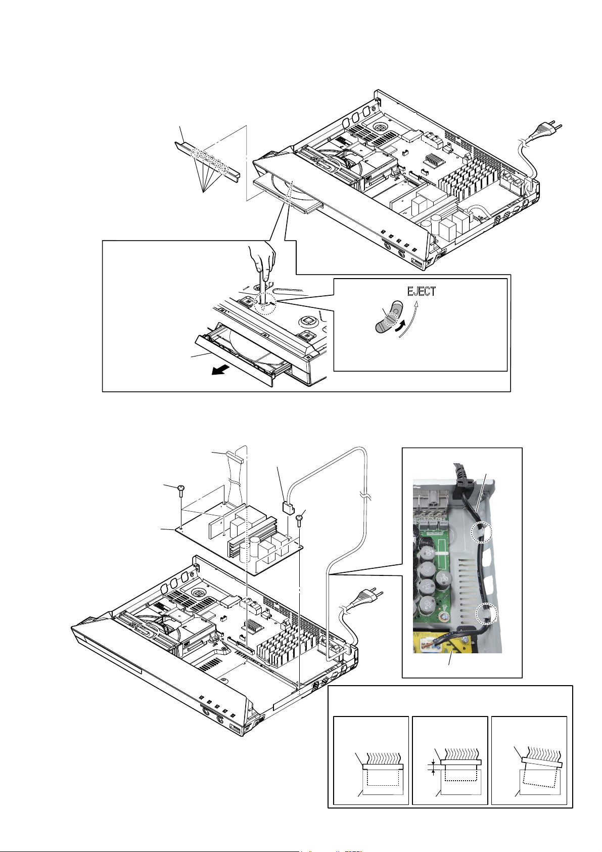
2-4. POWER Board................................................................ 7
2-5. Front Panel Block ........................................................... 8
2-6. BT Antenna (ANT1), POWER KEY Board,
FUNCTION KEY Board ................................................ 9
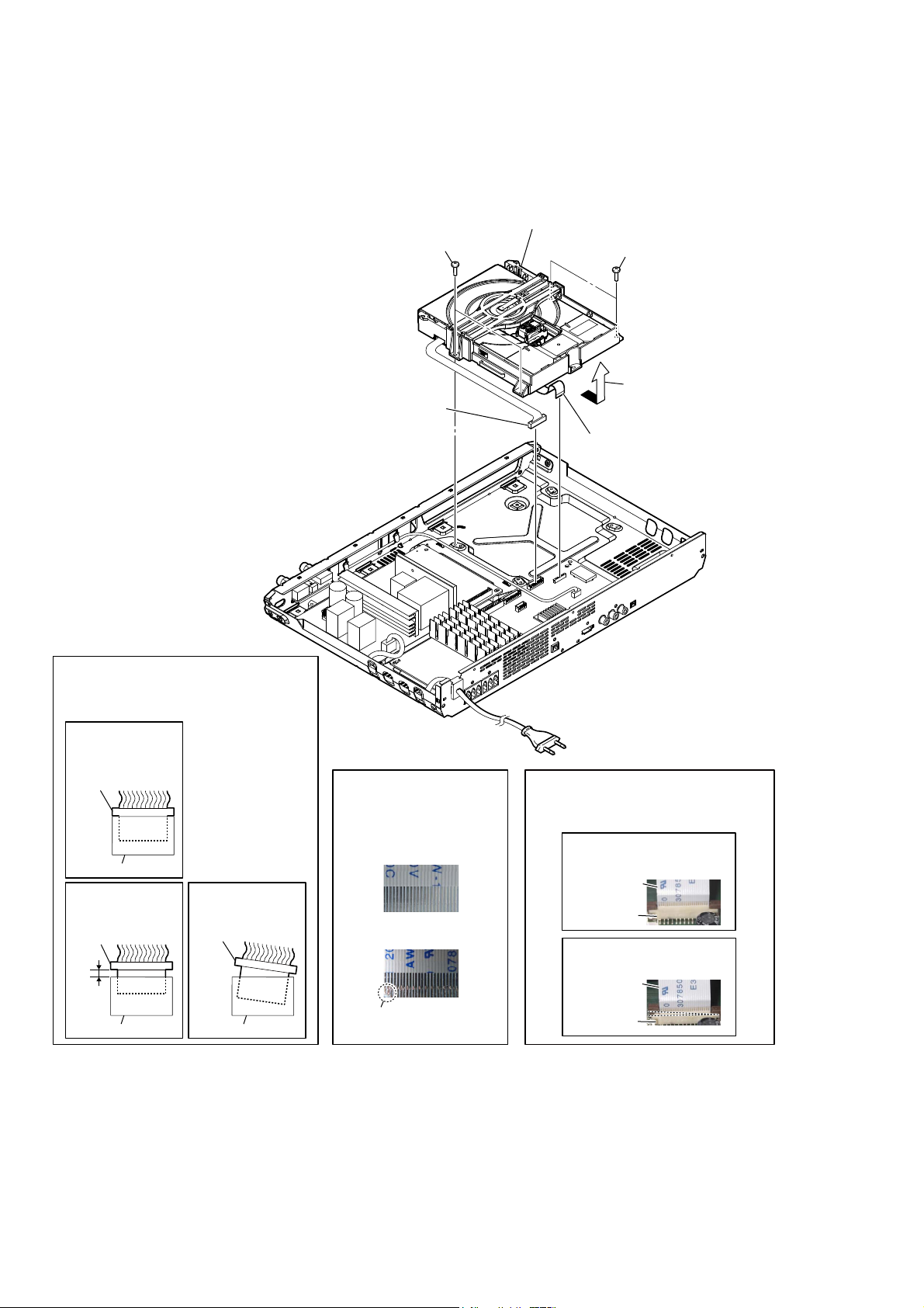
2-7. DVD Mechanism Deck Block ........................................ 10
2-8. DVD Mechanism Deck (CMS-LS5FP) .......................... 11
2-9. Holder Chuck.................................................................. 12
2-10. Tray Disc-1 ..................................................................... 12
2-11. Tray Disc-2 ..................................................................... 13
2-12. Optical Pick-up Block-1 ................................................. 14
2-13. Optical Pick-up Block-2 ................................................. 15
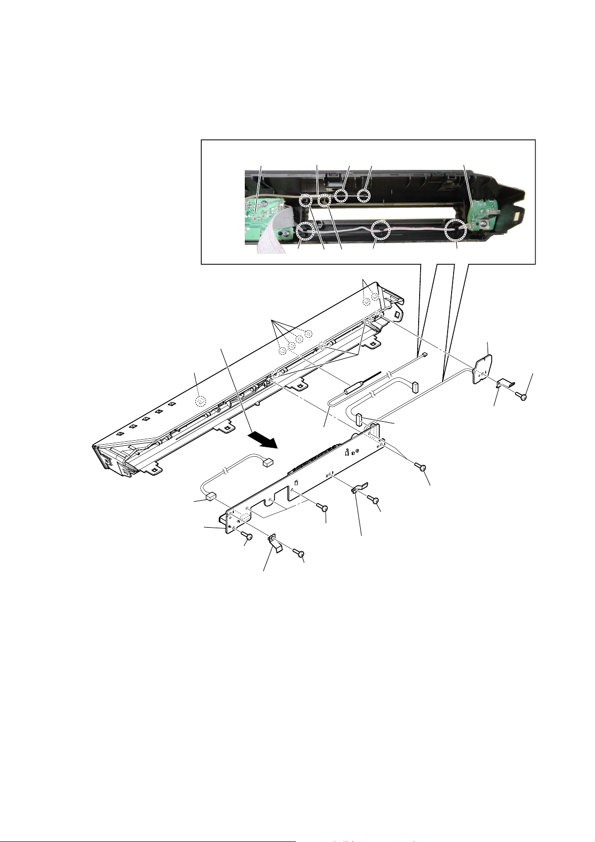
2-14. MIC Board ...................................................................... 16
2-15. MAIN Board ................................................................... 17
3. TEST MODE ............................................................ 18
4. TROUBLESHOOTING .......................................... 19
5. DIAGRAMS
5-1. Block Diagram................................................................ 20
5-2. Printed Wiring Board - MIC Board - .............................. 21
5-3. Schematic Diagram - MIC Board -................................. 21
5-4. Printed Wiring Board
- MAIN Board (Component Side) -................................ 22
5-5. Printed Wiring Board
- MAIN Board (Conductor Side) -.................................. 23
5-6. Schematic Diagram - MAIN Board (1/6) -..................... 24
5-7. Schematic Diagram - MAIN Board (2/6) -..................... 25
5-8. Schematic Diagram - MAIN Board (3/6) -..................... 26
5-9. Schematic Diagram - MAIN Board (4/6) -..................... 27
5-10. Schematic Diagram - MAIN Board (5/6) -..................... 28
5-11. Schematic Diagram - MAIN Board (6/6) - ..................... 29
5-12. Printed Wiring Boards - PANEL Section - ..................... 30
5-13. Schematic Diagram - PANEL Section -.......................... 31
5-14. Printed Wiring Board
- POWER Board (Component Side) -............................. 32
5-15. Printed Wiring Board
- POWER Board (Conductor Side) - .............................. 33
5-16. Schematic Diagram - POWER Board - .......................... 34
6. EXPLODED VIEWS
6-1. Top Cover Section........................................................... 42
6-2. Front Panel Section......................................................... 43
6-3. Chassis Section ............................................................... 44
6-4. DVD Mechanism Deck Section (CMS-LS5FP) ............. 45
7. ELECTRICAL PARTS LIST .............................. 46
Accessories are given in the last of the electrical parts list.
TABLE OF CONTENTS
SAFETY-RELATED COMPONENT WARNING!
COMPONENTS IDENTIFIED BY MARK 0OR DOTTED LINE
WITH MARK 0ON THE SCHEMATIC DIAGRAMS AND IN
THE PARTS LIST ARE CRITICAL TO SAFE OPERATION.
REPLACE THESE COMPONENTS WITH SONY PARTS
WHOSE PART NUMBERS APPEAR AS SHOWN IN THIS
MANUAL OR IN SUPPLEMENTS PUBLISHED BY SONY.
CAUTION
Use of controls or adjustments or performance of procedures
other than those specified herein may result in hazardous radia-
tion exposure.
NOTES ON CHIP COMPONENT REPLACEMENT
• Never reuse a disconnected chip component.
• Notice that the minus side of a tantalum capacitor may be dam-
aged by heat.
Trademarks
is system incorporates with Dolby* Digital
and Dolby Pro Logic adaptive matrix
surround decoders.
* Manufactured under license from Dolby
Laboratories.
Dolby, Pro Logic, and the double-D
symbol are trademarks of Dolby
Laboratories.
is system incorporates High-Denition
Multimedia Interface (HDMI™) technology.
e terms HDMI and HDMI High-
Denition Multimedia Interface, and the
HDMI Logo are trademarks or registered
trademarks of HDMI Licensing LLC in the
United States and other countries.
is a trademark of DVD Format/Logo
Licensing Corporation.
“PlayStation” and “PS3” are registered
trademarks of Sony Computer Entertainment
Inc.
“BRAVIA” is a trademark of Sony
Corporation.
MPEG Layer-3 audio coding technology and
patents licensed from Fraunhofer IIS and
omson.
Windows Media is either a registered
trademark or trademark of Microsoft
Corporation in the United States and/or other
countries. is product is protected by certain
intellectual property rights of Microsoft
Corporation. Use or distribution of such
technology outside of this product is
prohibited without a license from Microsoft
or an authorized Microsoft subsidiary.
ABOUT MPEG-4 VISUAL: THIS PRODUCT
IS LICENSED UNDER THE MPEG-4
VISUAL PATENT PORTFOLIO LICENSE
FOR THE PERSONAL AND
NONCOMMERCIAL USE OF A
CONSUMER FOR DECODING VIDEO IN
COMPLIANCE WITH THE MPEG-4
VISUAL STANDARD (“MPEG-4 VIDEO”)
THAT WAS ENCODED BY A CONSUMER
ENGAGED IN A PERSONAL AND
NONCOMMERCIAL ACTIVITY AND/OR
WAS OBTAINED FROM A VIDEO
PROVIDER LICENSED BY MPEG LA TO
PROVIDE MPEG-4 VIDEO.
NO LICENSE IS GRANTED OR SHALL BE
IMPLIED FOR ANY OTHER USE.
ADDITIONAL INFORMATION
INCLUDING THAT RELATING TO
PROMOTIONAL, INTERNAL AND
COMMERCIAL USES AND LICENSING
MAY BE OBTAINED FROM MPEG LA,
LLC. SEE http://www.mpegla.com/
e Bluetooth® word mark and logos are
registered trademarks owned by Bluetooth
SIG, Inc. and any use of such marks by Sony
Corporation is under license. Other
trademarks and trade names are those of their
respective owners.
All other trademarks are trademarks of their
respective owners.
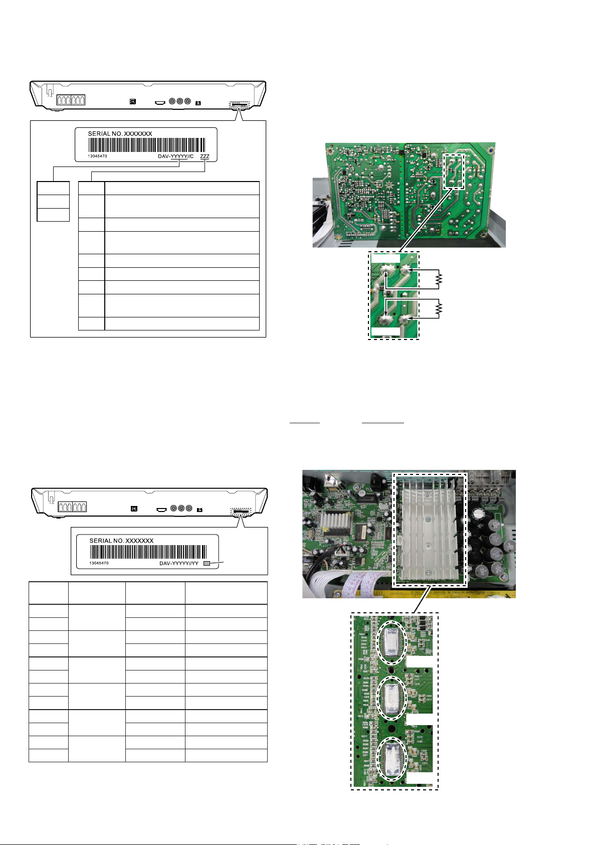
is appliance
is classified as a
CLASS 1
LASER product.
is marking is
located on the
rear exterior.
Ver. 1.3