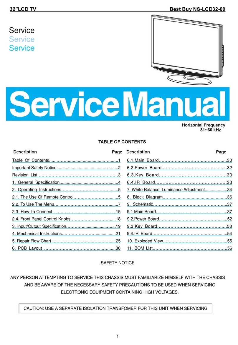
TABLE OF CONTENTS
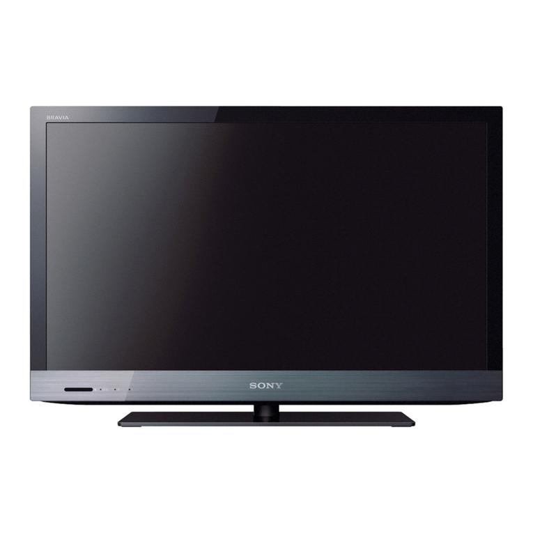
KDL- 22, 26 EX420, 32,40,46 EX520
RM-GD020, CD013
KDL- 22 EX423, 26 EX423, 32 EX420, 32, 40, 46 EX523
RM-GD020
ection Title Page
1. SAFETY NOTES
1-1. Caution Handling of LCD Panel ........................……………..…...................... 3
1-2. Safety Check Out ......................................…………...………….........................
3
1-3. Leakage Tes t ........................................................................................................
3
1-4.
How to find a
ood earth
round ......................................…………
4
Section Title Page
5. DIAGRAMS
5-1. Block Diagram ……………........................................................................................ 56
5-2. Wire Dressing
5-2-1. KDL-22EX420, 22EX423 ................................................................................. 60
5-2-2. K DL-26EX420, 26EX423 ................................................................................. 61
1-5. WARNING and Caution ....................................................................................... 4
1-6. Lead Free Inform ation ......................................................................................... 4
1-7. Information regarding Bezel and Panel………………………………………
6
2. SELF DIAGNOSTIC FUNCTION
2-1. Overview of Control Buttons ……………...........................................................
16
LED Display Specification
,
5-2-3. KDL-32EX420, 32EX520, 32EX523 ...............................................................62
5-2-4. K DL-40EX520, 40EX523………………………………………….................. 63
5-2-5. K DL-46EX520, 46EX523………………………………………...................... 64
5-3. Connector Diagram ..................……………………………………………………65
5-4. Circuit Board Location
5-4-1. KDL-22EX420, 22EX423 ................................................................................. 68
5-4-2 KDL-26EX420 26EX423 68
-
.
..................................................................................
2-3. LED Display Control ............................................................................................
16
2-4. LED Pattern ...........................................................................................................
17
2-5. Standby LED Error Dis play ................................................................................. 17
2-6. Triage Chart ........................................................................................................... 18
3. TROUBLE SHOOTING
5-4-2. KDL-26EX420, 26EX423 ................................................................................. 68
5-4-3. KDL-32EX420, 32EX520, 32EX523 ...............................................................68
5-4-4. K DL-40EX520, 40EX523………………………………………….................. 68
5-4-5. K DL-46EX520, 46EX523………………………………………...................... 68
6. DISASSEMBLY, EXPLODED VIEWS AND OTHER PARTS
6-1. KDL-22EX420, 22EX423 ................................................................................. 69
62 KDL 26EX420 26EX423 73
3-1. Power Problem …………..................................................................................... 19
3-2. Standby Led Blinking ........................................................................................... 19
3-3. Power (Green) LED Blinking............................................................................... 27
3-4. No Picture …………………………………………………….............................
28
3-5. No Sound ………………………………………………………………………
30
3-6. TV Comm ander and Keys Malfunction ........................................................ 30
-
Network Malfunction……………………………………......................................
6-2. KDL-26EX420, 26EX423 ................................................................................. 73
6-3. KDL-32EX420, 32EX520, 32EX523 ...............................................................76
6-4. KDL-40EX520, 40EX523………………………………………………………79
6-5. KDL-46EX520, 46EX523………………………………………….................. 82
6-6. Other Parts .....................................................……………………….............…85
PERATIN
IN
TRU
TI
N
Malfunction……………………………………......................................
3-8.
Camera Malfunction ………………………………………………………
35
3-9. 3D Malfunction…………………………………………………………………… 36
3-10. HDD-Rec Malfunction …………………………………………………………
37
3-11. Skype Trouble Shooting Flow …………………………………………………
38
3-12. Trouble Shooting Reference …………………………………………………
40
.
4-1. Acces s ing Self Diagnostic Menu …………....................................................... 46
4-2. Accessing Service Mode ..................................................................................... 47
4-3. Transition of Each Module in Service Mode …………....................................
47
4-4. Change Data by Service Mode 1 ……………………………………………… 48
4-5. Change Data by Service Mode 2 ……………………………………………… 49
4-6. White Balance Adjustment ……………………………………………………
50
4-7. Restore White Balance /Gamma Adj-data to B Board ……………………
51
4-8. Change the Emitter Output Level ……………………………………………
51
4-9.
Viewing VCOM Test Pattern ……………………………………………
52
4-10. How to do Shipping Condition ………………………………………………
53
4-11. Remote Commander Function………………………………………………
53
Index Flow of Service Control
.
…………………………………………………
2
