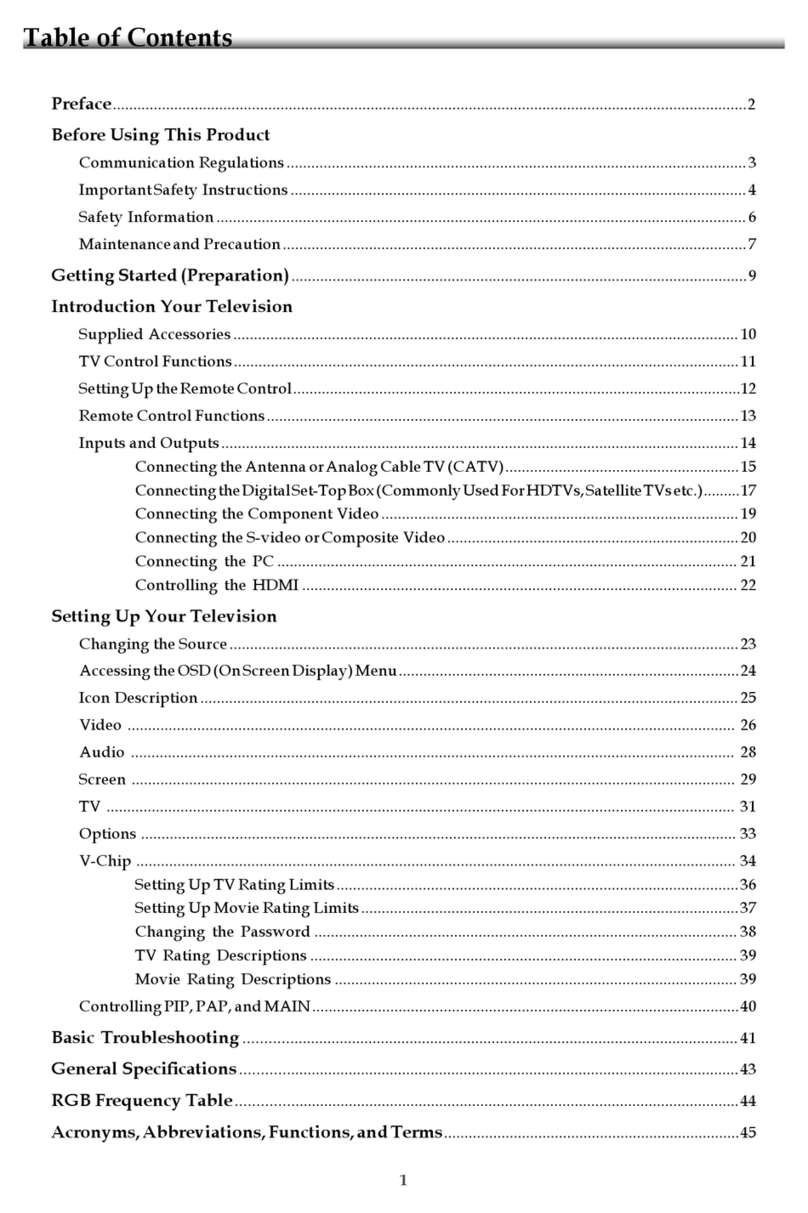
Table of content
3
Description Page
WARNINGS AND CAUTIONS………………………………………… 4
USE CAUTION WHEN HANDLING THE LCD PANEL…………… 5
SAFETY CHECK-OUT………………………………………………… 6
SELF DIAGNOSIS FUNCTION……………………………………… 8
SERVICE POSITION…………………………………………………… 9
SEC 1. DISASSEMBLY AND PARTS LIST…………………………… 11
1-1. KDL-32R304B CL3……………………………………………… 12
1-1-1. BASE STAND……………………………………………… 12
1-1-2. REAR COVER ……………………………………………… 13
1-1-3. POWER BOARD, A BOARD AND SPEAKER ………… 14
1-1-4. LCD PANEL, DECO and COVER, BOTTOM ………… 15
1-1-5. MISCELLANEOUS………………………………………… 16
1-2. KDL-40R354B CL3…………………………………………….… 17
1-2-1. BASE STAND……………………………………………… 17
1-2-2. REAR COVER ……………………………………………… 18
1-2-3. POWER BOARD, A BOARD AND SPEAKER ………… 19
1-2-4. LCD PANEL, DECO and COVER, BOTTOM ………… 20
1-2-5. MISCELLANEOUS………………………………………… 21
1-3. How to disassemble rear cover [KDL-32R304B CL3 /KDL-40R354B
CL3] …………………………………………………………….……….... 22
1-4. How to disassemble Deco [KDL-32R304B CL3 /KDL-40R354B
CL3] …………………………………………………….…………………. 23
1-5. How to disassemble LVDS cable [KDL-32R304B CL3 /KDL-
40R354B CL3] ……………………………………………………………. 24
1-6. How to disassemble IR Board [KDL-32R304B CL3 /KDL-40R354B
CL3] ……………………………………………………………………….. 25
KDL-32R304B CL3 /KDL-40R354B CL3
Description Page
1-7. How to assemble the Himeron Countermeasure of panel
[KDL-32R304B CL3 /KDL-40R354B CL3] ………………… 26
1-8. How to assemble the Himeron Countermeasure of panel[KDL-
32R304B CL3 /KDL-40R354B CL3] …………………………….…… 27
1-8-1. KDL-32R304B CL3 ……………………………………… 27
1-8-2. KDL-40R354B CL3……………………………………… 29
SEC 2. ADJUSTMENT…………………………………………………… 30
SEC 3. DIAGRAMS AND CHASSIS STRUCTURE………………… 32
3-1. BLOCK DIAGRAM……………………………………………… 32
3-2. CONNECTOR DIAGRAM……………………………………… 33
3-3. CIRCUIT BOARDS LOCATION……………………………… 34
3-4. Tape location……………………………………………………… 35
APPENDIX-1 Trouble analysis flow…………………………………… 37
APPENDIX-2 Software data update…………………………………… 38
APPENDIX-3 Operation Time, Boot Count, Panel Operation Time 42
APPENDIX-4 Edit MODEL NAME and Serial Number..…………… 43
