manuals.online logo
Brands
  1. Home
  2. •
  3. Brands
  4. •
  5. Sony
  6. •
  7. Mini Disc Player
  8. •
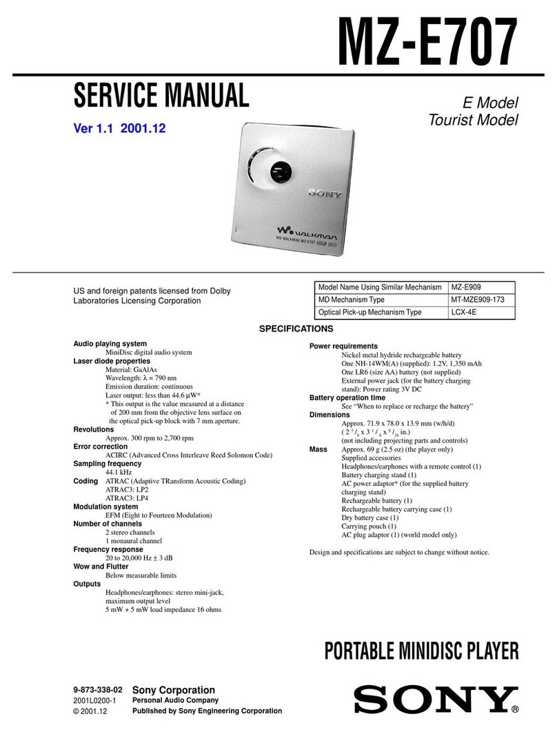
  9. Sony MD Walkman MZ-E25 User manual

Sony MD Walkman MZ-E25 User manual

MICROFILM
SERVICE MANUAL
PORTABLE MINIDISC PLAYER
US Model
Canadian Model
AEP Model
UK Model
E Model
Australian Model
Model Name Using Similar Mechanism NEW
Mechanism Type MT-MZE35-140
Optical Pick-up Name ODX-1B
SPECIFICATIONS
MZ-E25
US and foreign patents licensed from Dolby
Laboratories Licensing Corporation.
– 2 –
TABLE OF CONTENTS
1. GENERAL ................................................................... 3
2. DISASSEMBLY ......................................................... 5
3. TEST MODE.............................................................. 9
4. ELECTRICAL ADJUSTMENTS......................... 12
5. DIAGRAMS
5-1. Block Diagram ................................................................ 14
5-2. Printed Wiring Board ...................................................... 16
5-3. Schematic Diagram ......................................................... 19
5-4. IC Pin Function Description ........................................... 28
6. EXPLODED VIEWS................................................ 31
7. ELECTRICAL PARTS LIST ............................... 33
Flexible Circuit Board Repairing
• Keep the temperature of the soldering iron around 270 ˚C dur-
ing repairing.
• Do not touch the soldering iron on the same conductor of the
circuit board (within 3 times).
• Be careful not to apply force on the conductor when soldering
or unsoldering.
Notes on chip component replacement
• Never reuse a disconnected chip component.
• Notice that the minus side of a tantalum capacitor may be dam-
aged by heat.
ATTENTION AU COMPOSANT AYANT RAPPORT
À LA SÉCURITÉ!
LES COMPOSANTS IDENTIFIÉS PAR UNE MARQUE !
SUR LES DIAGRAMMES SCHÉMATIQUES ET LA LISTE
DES PIÈCES SONT CRITIQUES POUR LA SÉCURITÉ
DE FONCTIONNEMENT. NE REMPLACER CES COM-
POSANTS QUE PAR DES PIÈCES SONY DONT LES
NUMÉROS SONT DONNÉS DANS CE MANUEL OU
DANS LES SUPPLÉMENTS PUBLIÉS PAR SONY.
SAFETY-RELATED COMPONENT WARNING!!
COMPONENTS IDENTIFIED BY MARK !OR DOTTED
LINE WITH MARK !ON THE SCHEMATIC DIAGRAMS
AND IN THE PARTS LIST ARE CRITICAL TO SAFE
OPERATION. REPLACE THESE COMPONENTS WITH
SONY PARTS WHOSE PART NUMBERS APPEAR AS
SHOWN IN THIS MANUAL OR IN SUPPLEMENTS PUB-
LISHED BY SONY.
CAUTION
Use of controls or adjustments or performance of procedures
other than those specified herein may result in hazardous ra-
diation exposure.
This MiniDisc player is classified as a CLASS 1
LASER product.
The CLASS 1 LASER PRODUCT lavel is located
on the rear exterior.
– 3 –
SECTION 1
GENERAL This section is extracted from
instruction manual.
– 4 –
– 5 –
UPPER LID ASS’Y
BOTTOM PANEL ASS’Y
Note on installation:
When mounting, shift S301, S802, and S805 in
the arrow direction, then shift the knobs (HOLD),
(DOLBY), and (OPEN) in the arrow direction so
as to adjust each knob and switch position.
Note: Follow the disassembly procedure in the numerical order given.
SECTION 2
DISASSEMBLY
• This set can be disassembled in the order shown below.
SET UPPER LID ASS’Y
BOTTOM
PANEL ASS’Y MAIN BOARD ORNAMENTAL
BELT ASS’Y MECHANISM
DECK SECTION
(MT-MZE35-140)
OPTICAL PICK-UP
(ODX-1B)
SECTION ASS’Y
2
precision screw
(M1.4)
1
Moving the knob (OPEN) in the direction
A
,
open the upper LID ass’y.
2
precision screw
(M1.4)
2
two precision screws
(M1.4)
3
upper LID ass’y
A
2
bottom panel ass’y
1
two precision screw
s
(M1.4)
knob (OPEN)
knob (DOLBY)
knob (HOLD)
S802
1
two precision screws
(M1.4)
1
two precision screws
(M1.4)
3
collar (DC IN) S301
S805
– 6 –
MAIN BOARD
4
two precision screws
(M1.4)
1
battery case lid
3
two screws
(M1.4
×
2)
3
two screws
(M1.4
×
2)
2
switch uni
t
(CN801)
8
MAIN boar
d
6
flexible board (CLV)
(CN551)
7
flexible board
(CN501)
5
Open the MAIN board
to the arrow direction.
– 7 –
ORNAMENTAL BELT ASS’Y
1
boss
2
Expand ornamental belt ass’y in the
arrow direction to remove.
1
boss
1
boss
1
boss
1
boss
1
boss
1
two screws (MD)
2
Set chassis ass’y
3
mechanism deck section
(MT-MZE35-140)
MECHANISM DECK SECTION (MT-MZE35-140)
– 8 –
OPTICAL PICK-UP (ODX-1B) SECTION ASS’Y
3
optical pick-up (ODX-1B)
section ass’y
1
precision scre
w
4
main shaft
2
flexible board
– 9 –
SECTION 3
TEST MODE
General
• In the TEST mode, this set provides the Auto mode in which
both CD and MO are adjusted automatically. In theAuto mode,
whether a disc is CD or MO is discriminated, then each
adjsutment is automatically executed sequentially. If a fault is
found, it is displayed.Also, in the Servo mode, each item can be
adjusted automatically.
EnteringTEST Mode
To enter the TEST mode, the following two methods are avail-
able:
Method-1. Entry by key input
Turn on the HOLD switch on the main set, and while pressing
pkey on the main set, press the following keys on the remote
controller in this order.
+→+→=→=→+→=→+→=→
P→P
Method-2. Entry by shorting the test point
Bridge the TAP801 (TEST) with a solder (connect IC801 #™ to
GND) on the MAIN board, turn on the POWER switch, and press
(key.
ReleasingTEST Mode
1. Turn off the POWER switch.
2. Remove the solder bridge form TAP801 (TEST) on the MAIN
board. (This is required only when using Method-2.)
Operation inTEST Mode
In the TEST mode, the Remote controller LCD display is as shown
below:
• ROM version display → All ON → All OFF are repeated.
• To hold the display for confirmation, press the PLAY MODE
key.
Configuration ofTEST Mode
The TEST mode configuration of this set is as follows:
SERVO Mode
• Enter the TEST mode, press VOL −key and (key to select
the SERVO mode.
• When the second digit of mode number is not 0 and the first
digit is 0 (010, 020, 030, etc.), the optical pickup moves to out-
side track or inside track with +key or =key respec-
tively.
• To select other modes, refer to the TEST mode configuration.
1. Configuration of SERVO Mode
300 V3.000
Remote controller LCD
ROM version
display
Display in TEST Mode
+key
–key
+,
–
key
+,
–
key
+,
–
key
p
key
p
key
p
key
(
key
(
key
p
key
AUTO Mode
Auto?
SERVO Mode

0 0 0
AUDIO Mode

1 0 0
POWER Mode

3 0 0
MANUAL
Mode
Manu?
Start?
+,–key +,–key
p
key
p
key
p
key
p
key
p
key
p
key
123
(To page 10 )
SERVO Mode
0 0 0
OFFSET Adj.
0 1 0
Each time
(
key is press-
ed,
011-013
modes
are switched. (For each
mode, see relevant table)
Each time
(
key is press-
ed,
021-024
modes
are switched. (For each
mode, see relevant table)
Each time
(
key is press-
ed,
031-039
modes
are switched. (For each
mode, see relevant table)
LASER
POWER Adj.
0 2 0
MO Adj.
0 3 0
(
key
(
key
(
key
(
key
(
key
(
key
(
key
– 10 –
+,–key+,–key+,–key+,–key
+,–key
p
key
p
key
p
key
p
key
p
key
p
key
p
key
p
key
p
key
p
key
123
(To page 9 )
(
key
(
key
(
key
(
key
(
key
(
key
(
key
(
key
(
key
(
key
LOW REF CD Adj.
0 4 0
CD Adj.
0 5 0
SLED Move
0 6 0
AUTO Adj.
0 7 0
NV
0 9 0
Each time
(
key is
pressed,
041-048
modes are switched.
(For each mode, see
relevant table)
Each time
(
key is
pressed,
051-058
modes are switched.
(For each mode, see
relevant table)
Each time
(
key is
pressed,
061
and
062
modes are switched.
(For each mode, see
relevant table)
Each time
(
key is
pressed,
071-074
modes are switched.
(For each mode, see
relevant table)
Each time
(
key is
pressed,
091-093
modes are switched.
(For each mode, see
relevant table)
Return to OFFSET Adj.
(
010
)
2. Description of Each Mode
010 Offset Adjustment
Mode Description
011 Focus error offset
012 Tracking error offset
013 All servo ON
020 Laser Power Adjustment
Mode Description
021 MO power A
022 Low reflection CD power E
023 Low reflection CD power
024 CD power
030 MO Adjustment
Mode Description
031 MO EF balance (MO traverse)
032 MO EF gain
033 MO ABCD gain
034 MO focus gain
035 MO tracking gain
036 MO RF gain
037 MO ADIP gain
038 MO focus bias E
039 MO focus bias A
040 Low Reflection CD Adjustment
Mode Description
041 Low reflection CD EF balance
(CD traverse)
042 Low reflection CD EF gain
043 Low reflection CD ABCD gain
044 Low reflection CD focus gain
045 Low reflection CD tracking gain
046 Low reflection CD RF offset
047 Low reflection CD RF gain
048 Low reflection CD focus bias
050 CD Adjustment
Mode Description
051 CD EF balance
052 CD EF gain
053 CD ABCD gain
(CD RF level check)
054 CD focus gain
055 CD tracking gain
056 CD RF offset
057 CD RF gain
058 CD focus bias
– 11 –
060 Sled Movement
Mode Description
061 Sled IN
062 Sled OUT 5
070 Auto Adjustment
Mode Description
071 Focus search
072 Access 32
073 ADER check
074 Tracking gain correction
090 NV
Mode Description
091 NV clear
092 Power OFF
AUDIO Mode
• Enter the TEST mode, and pressVOL −key, (key, and VOL
+ key in this order to select the AUDIO mode.
• To select other modes, refer to the TEST mode configuration.
1. Configuration of AUDIO Mode
• The mode No.112 is for S/N and cross talk, and 115 for distor-
tion factor and frequency characteristic.
• When VOL + / −key is pressed in any mode, the headphone
volume changes every step.
Also, When +or =key is pressed, the headphone volume
becomes maximum or minimum.
• Once the volume level was changed, fundamentally it contin-
ues, but it returns to default value when the mode is changed
from 114 to 115, or 118 to 119.
p
key
p
key
p
key
p
key
p
key
p
key
p
key
p
key
p
key
p
key
(
key
(
key
(
key
(
key
(
key
(
key
(
key
(
key
(
key
(
key
(
key
1kHz 0dB L/R

1 1 1
Headphone
output
–– 12dB
––
∞
–– 12dB
–– 12dB
–– 20dB
–– 20dB
–– 20dB
–– 20dB
–– 40dB
Infinity Zero

1 1 2
1kHz 0dB L

1 1 3
1kHz 0dB R

1 1 4
1kHz -20dB L/R

1 1 5
20Hz -20dB L/R

1 1 6
20kHz -20dB L/R

1 1 7
16kHz De-Emphasis

1 1 8
100kHz 0dB L/R

1 1 9
AUDIO Mode

1 0 0
PLAY TEST

1 1 0
– 12 –
SECTION 4
ELECTRICAL ADJUSTMENTS
Precautions on Adjustment
• In this set, the CD and MO adjsutment can be executed auto-
matically by selecting the TEST mode.
• Execute adjustment in the AUTO mode, then if NG occurred,
readjust faulty item in the SERVO mode.
Adjustment in AUTO Mode
1. Enter the TEST mode, and pressVOL + key to select theAUTO
mode.
2. Insert the CD Test disc (TDYS-1) or commercially available
SONY MO disc (already recorded).
3. Press (key twice, and the CD or MO is discriminated, then
respective items are automatically adjusted in the order as listed
in tables below.
• CD AUTO Adjustment
No. Mode Description
1061 Sled IN
2071 Focus search
3062 Sled OUT 5
4051 CD EF balance
5052 CD EF gain
6051 CD EF balance
7053 CD ABCD gain
8054 CD focus gain
9055 CD tracking gain
10 056 CD RF offset
11 057 CD RF gain
12 056 CD RF offset
13 058 CD focus bias
14 073 ADER check
15 074 Biaxial gain correction
POWER Mode
•Enter the TEST mode, and pressVOL −key, (key, and VOL
−key in this order to select the POWER mode.
•To select other modes, refer to the TEST mode configuration.
1. Configuration of POWER Mode
AUTO Mode
•Enter the TEST mode, and pressVOL + key to select theAUTO
mode.
•To select other modes, refer to the TEST mode configuration.
•In the AUTO mode, the Remote controller LCD display is as
shown below:
1. Configuration of AUTO Mode
p
key
(
key
p
key
(
key
(
key
POWER Mode

3 0 0
UNREG Check

3 1 0
POWER OFF

3 1 1
343 Auto?
p
key
p
key
p
key
p
key
(
key
(
key
(CD, MO discrimination)
CD Auto Adj.
MO Auto Adj.
Start?
OK
NG
OK
NG
MANUAL Mode
Manu?
AUTO Mode
Auto?
– 13 –
• MO AUTO Adjustment
No. Mode Description
1061 Sled IN
2071 Focus search
3062 Sled OUT
4031 MO EF balance
5032 MO EF gain
6031 MO EF balance
7033 MO ABCD gain
8034 MO focus gain
9035 MO tracking gain
10 036 MO RF gain
11 037 MO ADIP gain
12 039 MO focus bias A
13 073 ADER check
14 061 Sled IN
15 071 Focus search
16 041 Low reflection CD EF balance
17 042 Low reflection CD EF gain
18 041 Low reflection CD EF balance
19 043 Low reflection CD ABCD gain
20 044 Low reflection CD focus gain
21 045 Low reflection CD tracking gain
22 046 Low reflection CD RF offset
23 047 Low reflection CD RF gain
* Remote controller LCD display during automatic adjustment.
4. If automatic adjustment result is OK, the display is as follows:
5. If automatic adjustment result is NG, the display is as follows:
* In case of NG, select the SERVO mode, and readjust NG item
automatically.
Adjustment in SERVO Mode
1. Select each adjusting mode following the configuration of
SERVO mode, and the lower 2 digits of mode number and the
adjusted value written to the EEPROM are displayed on the
LCD.
2. Press Pkey, and the display changes as shown below and au-
tomatic adjustment is executed.
Note: Though the adjusted value can be changed to any value withVOL +
or −key, avoid frequent change.
3. Whem automatic adjustment is finished, the adjusted value
changes from blinking to lighting.
057
Mode No. being adjusted
Adjusted value (blinking)
074 End-OK
(blinking)
051
NG mode No. Error code
NG
052
Mode No. Adjusted value (lighting)
052
Adjusted value (blinking)
052
Adjusted value (blinking)
– 24 –
• Waveforms
1IC501 6, 7(VI, VJ) (Play Mode)
500 mV/DIV, 500 ns/DIV
2IC501 0(IA) (Play Mode)
20 mV/DIV, 1 µs/DIV
3IC501 1, 4(IE, IF) (Play Mode)
10 mV/DIV, 500 ns/DIV
4IC501 #¶ (RF-OUT) (Play Mode)
200 mV/DIV, 500 ns/DIV
5IC601 #ª (LRCK) (Play Mode)
1 V/DIV, 10 µs/DIV
6IC601 $¡ (BCK) (Play Mode)
1 V/DIV, 200 ns/DIV
7IC301 5(XT1) (Play Mode)
500 mV/DIV, 20 ns/DIV
Approx. 280 mVp-p
2.8 Vp-p
355 ns
1.4 Vp-p
16.9344 MHz
Approx. 43 mVp-p
Approx. 23 mVp-p
Approx. 760 mVp-p
2.8 Vp-p
23
µ
s
– 25 –
• IC Block Diagrams
IC301 AK4314-VF-E2
IC302 BA3577FS-E2
– 26 –
IC601 µPD63730AGC-9EU
IC901 MPC1830VMEL

Other manuals for MD Walkman MZ-E25

3

Other Sony Mini Disc Player manuals

Sony MDS-JE480 User manual

Sony

Sony MDS-JE480 User manual

Sony MDS-S50 User manual

Sony

Sony MDS-S50 User manual

Sony MDS-W1 User manual

Sony

Sony MDS-W1 User manual

Sony MDS-JB940 User manual

Sony

Sony MDS-JB940 User manual

Sony MDS-JB940 User manual

Sony

Sony MDS-JB940 User manual

Sony Walkman MZ-E505 User manual

Sony

Sony Walkman MZ-E505 User manual

Sony MZ-E30 User manual

Sony

Sony MZ-E30 User manual

Sony Hi-MD WALKMAN MZ-DH710 User manual

Sony

Sony Hi-MD WALKMAN MZ-DH710 User manual

Sony MXD-D1 User manual

Sony

Sony MXD-D1 User manual

Sony MDS-JB920 User manual

Sony

Sony MDS-JB920 User manual

Sony MD Walkman MZ-E75 User manual

Sony

Sony MD Walkman MZ-E75 User manual

Sony MDS-NT1 User manual

Sony

Sony MDS-NT1 User manual

Sony MDS-JA3ES - Es Minidisc Recorder User guide

Sony

Sony MDS-JA3ES - Es Minidisc Recorder User guide

Sony Hi-MD Walkman MZ-RH10 User manual

Sony

Sony Hi-MD Walkman MZ-RH10 User manual

Sony MZ-R90 Analog PCLink User manual

Sony

Sony MZ-R90 Analog PCLink User manual

Sony MDS-JE700 - Mini Disc Player User manual

Sony

Sony MDS-JE700 - Mini Disc Player User manual

Sony MZ-E70 User manual

Sony

Sony MZ-E70 User manual

Sony MZ-F40 User manual

Sony

Sony MZ-F40 User manual

Sony MDS-JB930 User manual

Sony

Sony MDS-JB930 User manual

Sony MZNH600D - Hi-MD Walkman Recorder User manual

Sony

Sony MZNH600D - Hi-MD Walkman Recorder User manual

Sony NET MD MDS-JB980 User manual

Sony

Sony NET MD MDS-JB980 User manual

Sony MDS-SP55 User manual

Sony

Sony MDS-SP55 User manual

Sony CDX-434RF - Compact Disc Changer System Product guide

Sony

Sony CDX-434RF - Compact Disc Changer System Product guide

Sony MD WALKMAN MZ-E300 User manual

Sony

Sony MD WALKMAN MZ-E300 User manual

Popular Mini Disc Player manuals by other brands

Sharp IM-MT899W Operation manual

Sharp

Sharp IM-MT899W Operation manual

Sharp MD-MS701H Service manual

Sharp

Sharp MD-MS701H Service manual

JVC XM-PX5SL instructions

JVC

JVC XM-PX5SL instructions

Sharp MD-S70H Operation manual

Sharp

Sharp MD-S70H Operation manual

Kenwood DMC-P33 Operation manual

Kenwood

Kenwood DMC-P33 Operation manual

JVC XM-PX55BU instructions

JVC

JVC XM-PX55BU instructions

Kenwood DMC-S33 Operation manual

Kenwood

Kenwood DMC-S33 Operation manual

Technics SJ-MD100 Service manual

Technics

Technics SJ-MD100 Service manual

Aiwa AM-HX70 Service manual

Aiwa

Aiwa AM-HX70 Service manual

manuals.online logo
manuals.online logoBrands
  • About & Mission
  • Contact us
  • Privacy Policy
  • Terms and Conditions

Copyright 2025 Manuals.Online. All Rights Reserved.