1. AUTO Mode
• When the STOP button is pressed while the AUTO menu
appears or during automatic adjustment, the mode changes to
the TEST mode stop state. At this time the adjustment value is
not output.
• As for operation during continuous playback refer to [Explanation
of TEST-PLAY mode].
• Adjustment NG: If the measurement value of adjustment FEO is
out of range,focus ON failure occurs or adjustment error or TZC
error occurs.
• When the high reflection disc is used, changes as follows.
TEO — FEO — Hf — Hg — Hb — Hf
• When the low reflection disc is used, changes as follows.
TEO — FEO — If — Lg — Lb — Lf — Gl — Gg — Gb — Lf
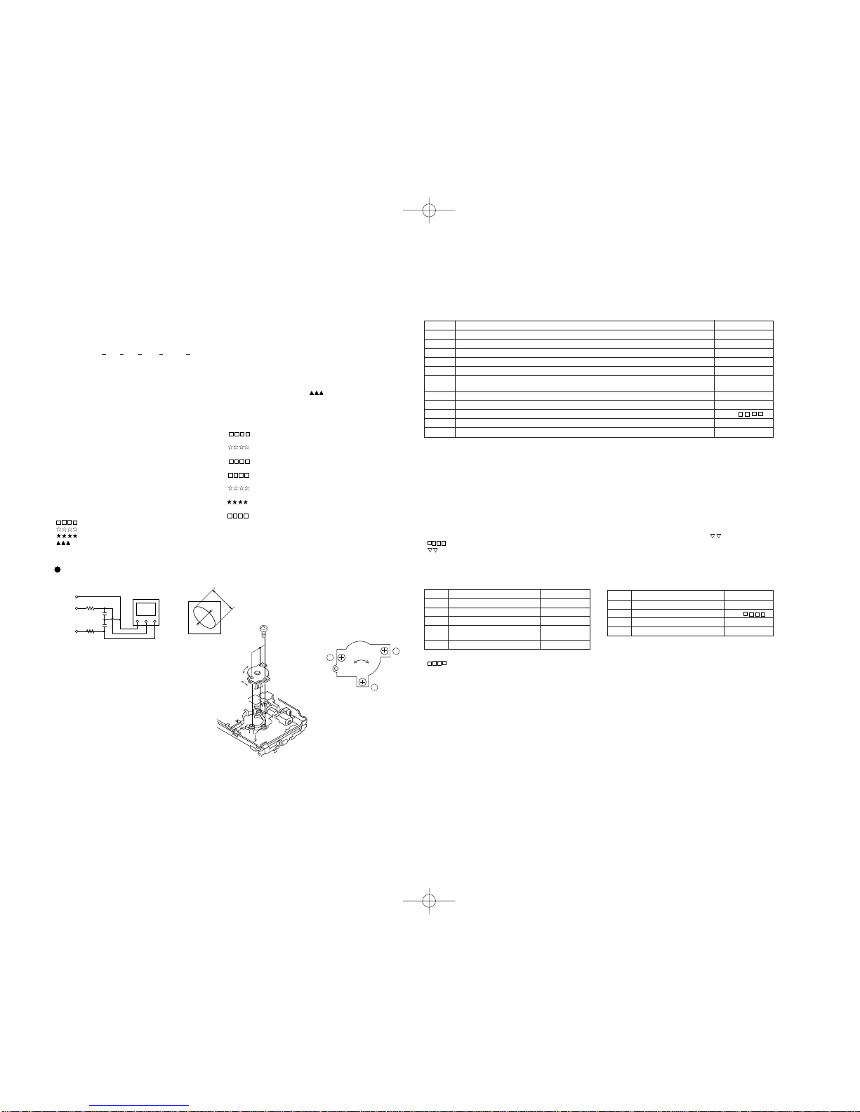
• Grating adjustment: When the focus servo and spin servo are
ON.
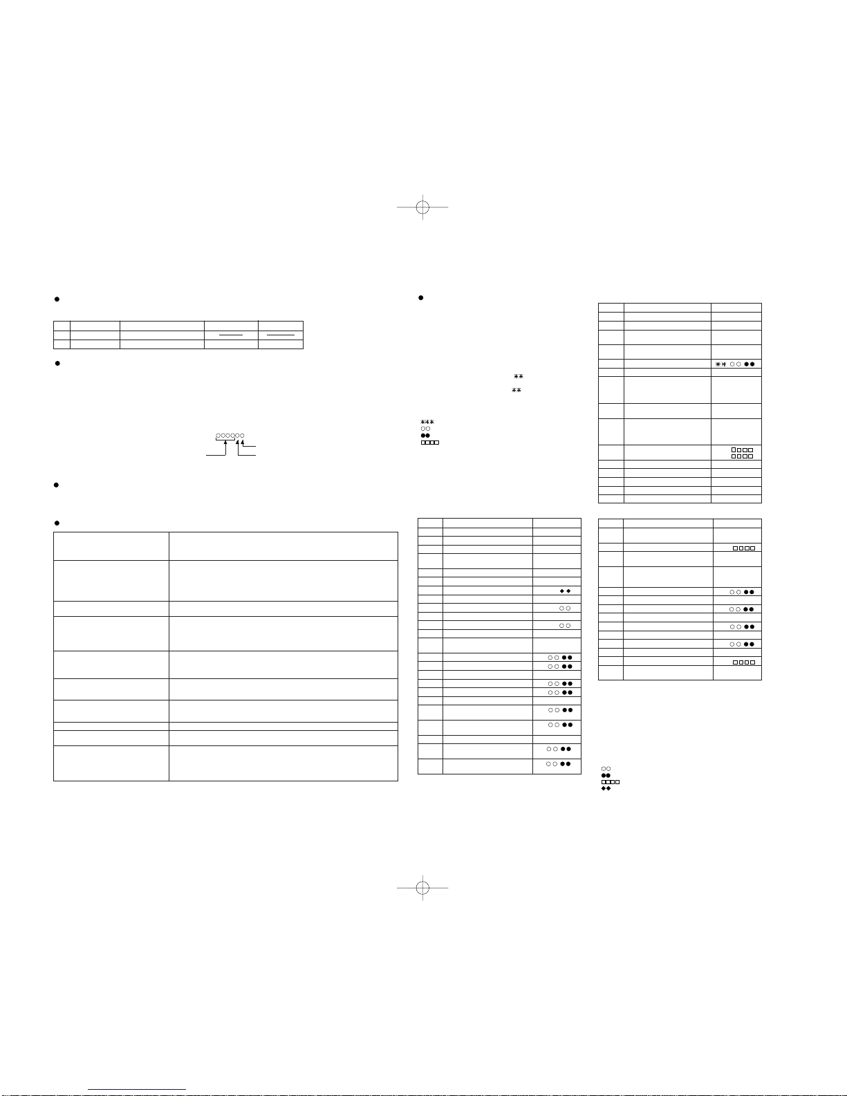
• : Adjustment name
• : Measurement value
• : Set value
• : Address
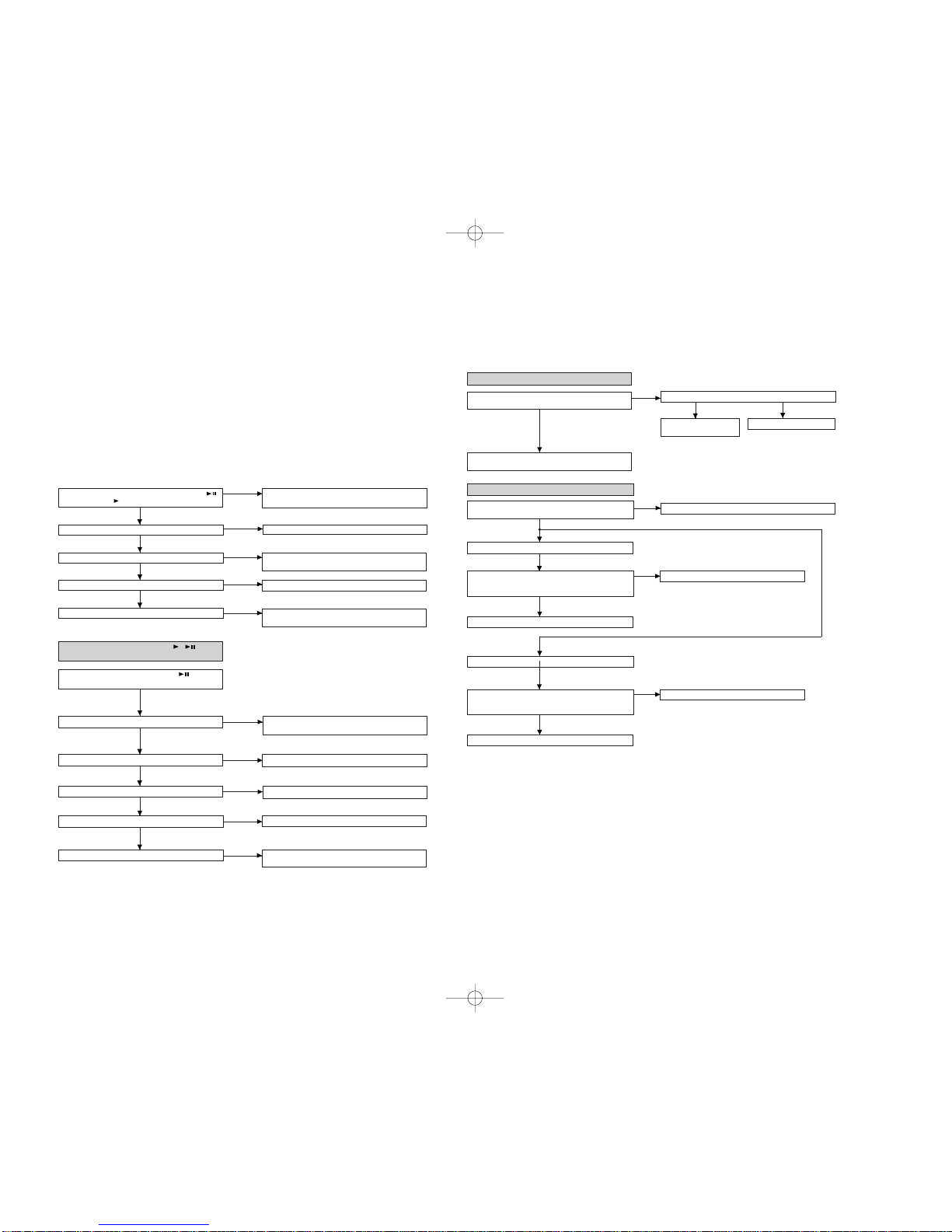
Operation in each TEST mode Step No. Operation and state Display
Step 1 Test mode STOP state [ T E S T ]
Step 2 BASS button.
Step 3 AUTO menu. [ A U T O ]
Step 4 PLAY button -->
Slide shift to innermost periphery
Step 5 Automatic adjustment [ ]
Step 6 End of adjustment
Step 7 When adjustment is OK, the
process proceeds to (8).
When adjustment is NG, the
process proceeds to (13).
Step 8 Grating adjustment, adjustment [ A D J . O K ]
value output
Step 9 When the PLAY button is pressed,
the process proceeds to (10).
When the STOP button is pressed,
the process proceeds to (12).
Step 10 Continuous playback (pit section) [ S Q ]
Continuous playback (groove section) [ A P ]
Step 11 STOP button
Step 12 Test mode STOP state [ T E S T ]
Step 13 Adjustment value output [ A D J . N G ]
Step 14 STOP button
Step 15 Test mode STOP state [ T E S T ]
2. MAMUAL Mode
Step 1 Test mode STOP state [ T E S T ]
Step 2 BASS button
Step 3 AUTO menu [ A U T O ]
Step 4 SKIP UP button x 1 times
(Or SKIP DOWN button x 9 times)
Step 5 MANUAL menu [ M A N U A L ]
Step 6 PLAY button
Step 7 Temperature measurement [ T M P : ]
Step 8 SKIP UP button
Step 9 Tracking error offset measurement [ T E O : ]
Step 10 SKIP UP button
Step 11 Focus error offset measurement [ F E O : ]
Step 12 SKIP UP button—Laser lighting [ L O N : _ _ ]
Step 13 SKIP UP button—
Slide shift to innermost periphery
Step 14-a
Focus gain rough adjustment (high reflection)
[ H f ]
Step 14-b
Focus gain rough adjustment (low reflection)
[ L f ]
Step 15 SKIP UP button
Step 16-a
Pit:Tracking gain adjustment (high reflection)
[ H g ]
Step 16-b
Pit:Tracking gain adjustment (low reflection)
[ L g ]
Step 17 SKIP UP button
Step 18-a Pit: [ H b ]
Tracking balance adjustment (high reflection)
Step 18-b Pit: [ L b ]
Tracking balance adjustment (low reflection)
Step 19 SKIP UP button
Step 20-a Pit: [ H f ]
Focus gain adjustment (high reflection)
Step 20-b Pit: [ L f ]
Focus gain adjustment (low reflection)
Step No. Operation and state Display
Step 21 Step (24) when SKIP UP button,
Step (22) when PLAY button.
Step 22 Pit section continuous playback [ S Q ]
Step 23 When the P-MODE button is pressed,
the process proceeds to (20-a) or (20-b).
Step 24 The high reflection disc is not accepted.
When the low reflection disc is used, the
process proceeds to (25).
Step 25 TOTAL signal level adjustment [ G l ]
Step 26 SKIP UP button
Step 27 Groove: Tracking gain adjustment [ G g ]
Step 28 SKIP UP button
Step 29 Groove: Tracking balance adjustment [ G b ]
Step 30 SKIP UP button
Step 31 Focus gain adjustment [ L f ]
Step 32 PLAY button
Step 33 Groove section continuous playback [ A P ]
Step 34 When the P-MODE button is pressed,
the process to (31).
Step No. Operation and state Display
• Reversing when the SKIP DOWN button is pressed.
• When the VOL UP button is pressed during adjustment, the set value
increases, and the new set value is output.
• When the VOL DOWN button is pressed during adjustment, the set
value reduces, and the new set value is output.
• When the VOL UP/DOWN button is held down, the setting changes
continuously, one cycle being 100 ms.
• When the STOP button is pressed while the MANUAL menu
appears, or during measurement or adjustment, the mode changes
to the TEST mode stop state.
• As for operation during continuous playback refer to [Explanation of
TEST-PLAY mode].
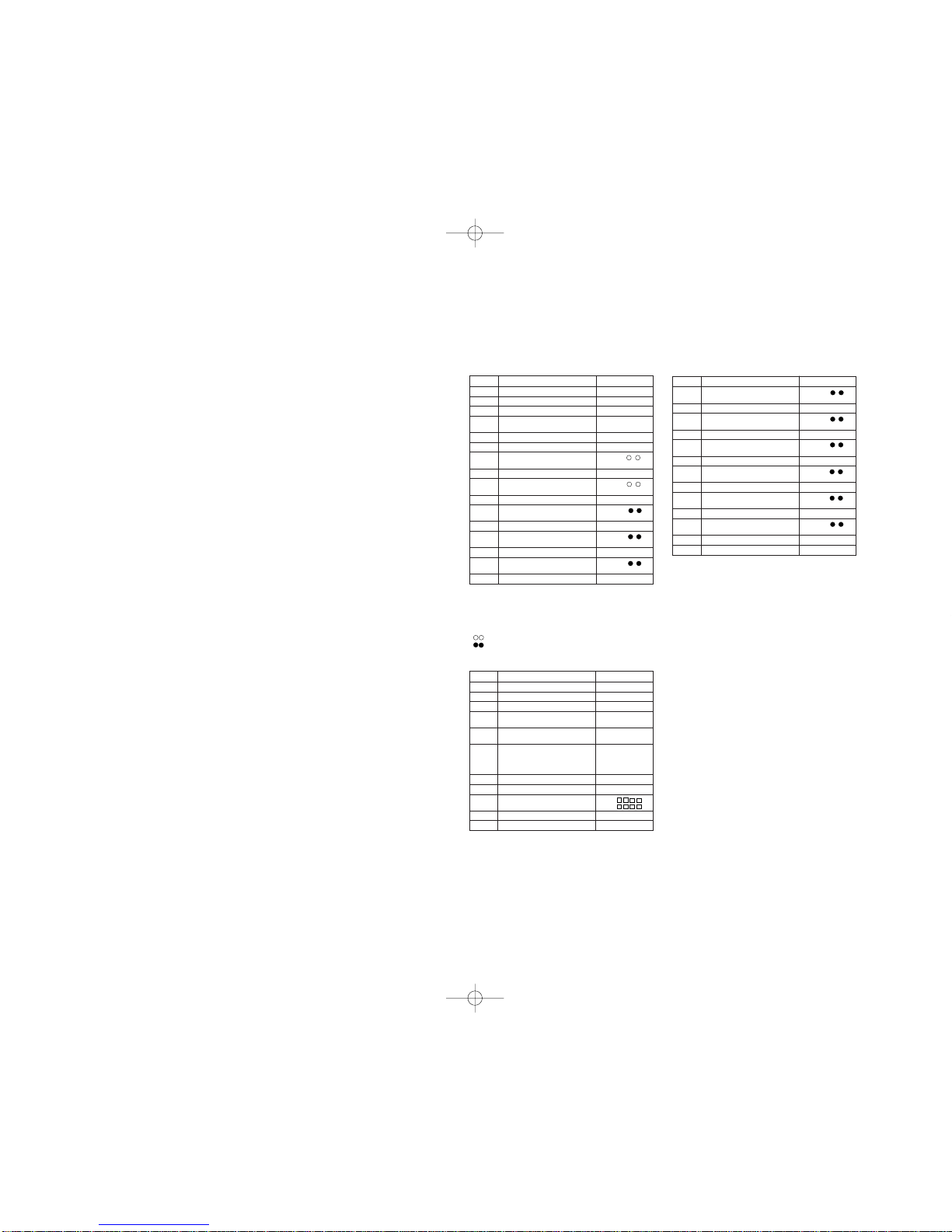
• : Measurement value
• : Set value
• : Address
• : Temperature code
Test disc
MD adjustment needs two types of disc, namely recording disc (low reflection disc) and playback-only disc (high
reflection disc).
Type Test disc Parts No. Price Code
1High reflection disc ESYA 1014 (SONY)
2 Low reflection disc Recording minidisc UDSKM0001AFZZ AZ
Note: Use the low reflection disc on which music has been recorded.
Microcomputer version EEPROM version
Destination
Entering the TEST mode
1. Setting at port (in standby state, disc-free state or power nonconnected state)
(1) Set the port as follows.
TEST1 : "Low"
TEST0 : "High"
(2) Press the PLAY button in the standby state (it is allowed to insert the disc or to connect the power supply).
(3) Test Mode STOP [ _ T E S T _ ]
2. Setting by special button operation (in standby state)
(1) Holding down the DISP button and ENTER button, press the PLAY button.
(2) Normal mode setting initialization (BASS setting, VOL setting, etc.)
(3) Indication of microcomputer version for one second [ ]
(4) Whole LCD lighting for 2 seconds
(5) Test Mode STOP [ _ T E S T _ ]
*When the PLAY button is pressed during indication (3) and (4), the process proceeds to (5).
Leaving the TEST mode
(1) Press the STOP button in the TEST mode stop state or version indicating state or whole LCD lighting state.
(2) EEPROM rewrite-enable area updating, adjustment error setting (so as to adjust all the items when the power supply is turned
on in the normal mode)
(3) Change to standby state
Test Mode
1. AUTO Mode • Automatic adjustment is performed. (After adjustment the grating adjustment mode is set.)
• Continuous playback is performed (Error rate indication, jump test).
• The temperature correction is performed only when servo start is performed, but the
posture correction is not performed.
2. MANUAL Mode • Temperature is displayed. (Updating in real time)
• Seeing the displayed measurement value/set value, make manualadjustment to set values
within the allowable range.
• Continuous playback is performed (error rate display, jump test).
• The temperature correction is performed only when servo start is performed, but the
posture correction is not performed.
3. RESULT Mode • Adjustment value is indicted.
• Adjustment value is changed manually. (in servo OFF state).
4. TEST-PLAY Mode • Continuous playback from the specified address is performed.
• 1 line, 10 lines or 400 lines manual jump is performed.
• C1 error rate display (pit section), ADIP error rate display (groove section)
• The temperature correction is performed only when servo start is performed, but the
posture correction is not performed during continuous playback.
5. TEST-REC Mode • Continuous record from the specified address is performed.
• Change of record laser output(servo gain is also changed according to laser output).
• The temperature correction is performed only when servo start is performed, but the
posture correction is not performed during continuous recording.
6. INNER Mode • Determine the position where the INNER switch is turned on.(only high reflection disc).
• The temperature correction is performed only when servo start is performed, but the
posture correction is not performed.
7. NORMAL Mode • The mode is changed from the TEST mode to the normal mode without adjustment.
• In the normal mode the internal operation mode, memory capacity, etc. areindicated.
• In the normal mode both temperature correction and posture correction are performed.
8. Digital input display Mode • Digital input information is displayed.
9. Error data display Mode • Error information is displayed.
• Error information is initialized.
10. E2-PROM setting mode • Factors of digital servo are changed manually. (Each servo is turned on individually.)
• Cut-off frequency of BASS1, BASS2 and BASS3 is selected manually.
• Temperature detection terminal voltage is measured, and the reference value is set.
• Defaults are selected and set.
• Setting of EEPROM protect area is updated. (In case of protect releasing)