Sony ZS-M50 User manual

Ver 1.1 1999.07
MICROFILM
ZS-M50
SERVICE MANUAL
PERSONAL MINIDISC SYSTEM
SPECIFICATIONS
AEP Model
UK Model
Tourist Model
Model Name Using Similar Mechanism NEW
MD MD Mechanism Type MDM-3Z
Section Optical Pick-up Type KMS-260A
CD Model Name Using Similar Mechanism CFD-S27
Section CD Mechanism Type KSM-213CDM
Optical Pick-up Type KSS-213C
Dolby noise reduction manufactured under license from
Dolby Laboratories Licensing Corporation.
“DOLBY” and the double-D symbol aare trademarks of
Dolby Laboratories Licensing Corporation.
– Continued on page 2 –

– 2 –
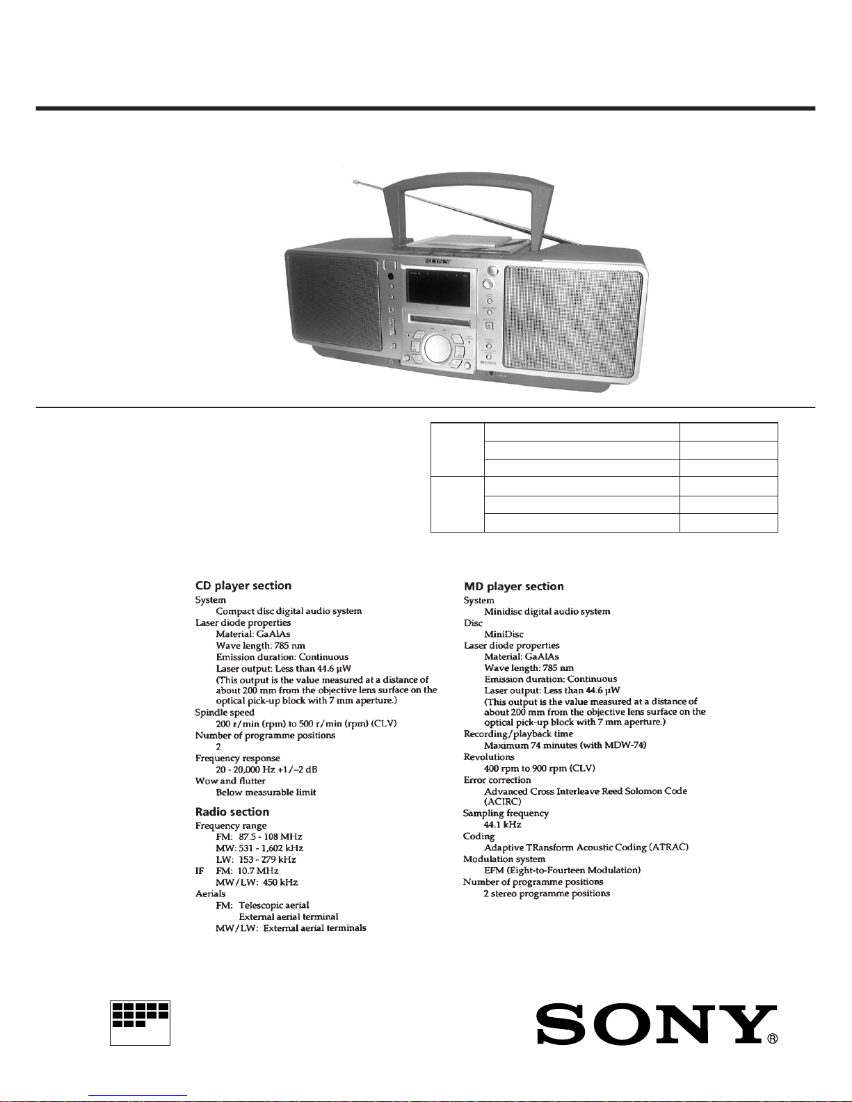
Specifications ........................................................................... 1
1. SERVICE NOTE........................................................... 3
2. GENERAL...................................................................... 5
3. DISASSEMBLY
3-1. Cabinet (Front) Sub ASSY,
Cabinet (Rear) Sub ASSY ......................................... 7
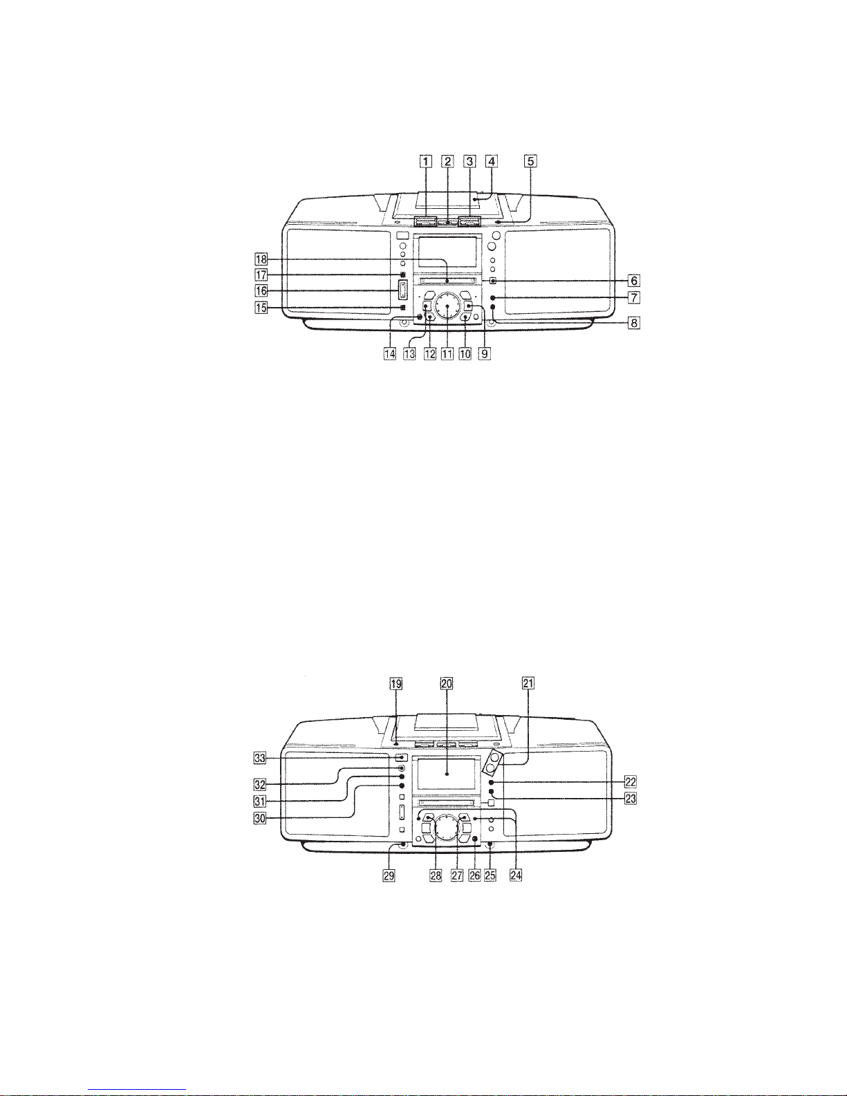
3-2. Control (L) Board...................................................... 8
3-3. Control (R) Board ..................................................... 8
3-4. Control (F) Board, JOG Board.................................. 8
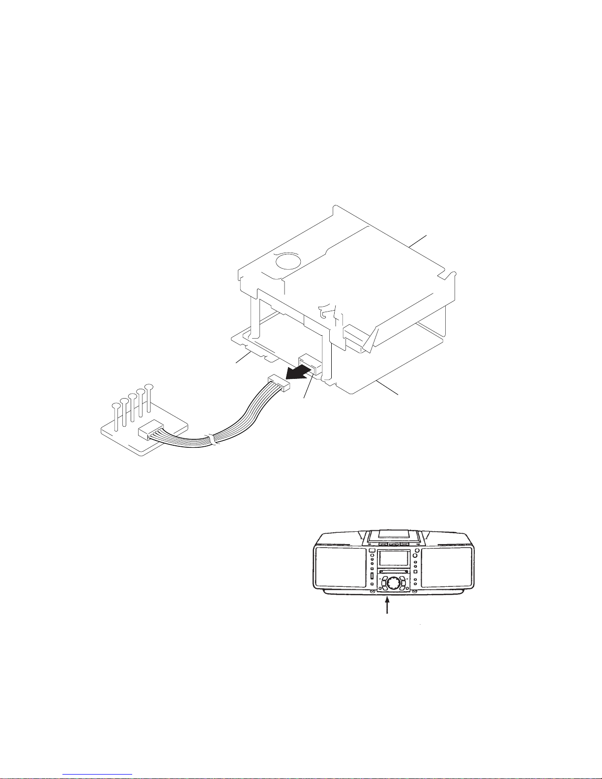
3-5. BATT Board .............................................................. 9
3-6. Power Board.............................................................. 9
3-7. Tuner Board, Antenna SW Board ............................. 9
3-8. Center Block Section .............................................. 10
3-9. Cabinet (Upper), Chassis (Main) ............................ 10
3-10.Optical Pick-up ASSY, CD Motor Board.................11
3-11.Control SW Board....................................................11
3-12.Motor Board, Belt, Motor (M703) ...........................11
3-13.LCD Board, BL Board ............................................ 12
3-14.Audio Board ............................................................ 12
3-15.Line Board............................................................... 13
3-16.Main Board ............................................................. 13
3-17.MD Block ASSY..................................................... 14
3-18.DG Board ................................................................ 14
3-19.Chassis (MD) .......................................................... 15
3-20.BD Board ................................................................ 15
3-21.Sub Chassis ASSY, MD Mechanism Deck ............. 16
3-22.Shutter ASSY .......................................................... 16
3-23.SW Board ................................................................ 17
3-24.“Head, Over Write”, Slider ASSY .......................... 17
3-25.MD Optical Pick-up Block ..................................... 18
4. TEST MODE
4-1. Caution When Using the Test Mode......................... 19
4-2. Test Mode Settings ................................................... 19
4-3. Releasing the Test Mode........................................... 19
4-4. Basic Operations of the Test Mode........................... 19
4-5. Selecting the Test Mode............................................ 19
4-6. Functions of Other Buttons ...................................... 20
4-7. Test Mode Display .................................................... 20
TABLE OF CONTENTS
5. ADJUSTMENTS
MD Section ...................................................................... 21
CD Section ....................................................................... 24
Display Section ................................................................ 25
Tuner Section ................................................................... 26
6. DIAGRAMS
6-1. Explanation of IC Terminals ................................... 28
6-2. Block Diagram (Main Section) ............................... 35
6-3. Block Diagram (MD Section) ................................. 39
6-4. Printed Wiring Boards –Main Section – ................. 43
6-5. Schematic Diagram –Main Section (1/3) – ............. 47
6-6. Schematic Diagram –Main Section (2/3) – ............. 51
6-7. Schematic Diagram –Main Section (3/3) – ............. 55
6-8. Printed Wiring Boards –Audio Section –................ 58
6-9. Schematic Diagram –Audio Section – .................... 61
6-10.Schematic Diagram –DG Section – ........................ 66
6-11.Printed Wiring Boards –DG Section – .................... 71
6-12.Printed Wiring Boards –Tuner Section – ................ 73
6-13.Schematic Diagram –Tuner Section –..................... 75
6-14.Schematic Diagram –Control Section – .................. 78
6-15.Printed Wiring Boards –Control Section – ............. 81
6-16.Printed Wiring Boards –BD Section – .................... 83
6-17.Schematic Diagram –BD Section – ........................ 85
7. EXPLODED VIEWS
7-1. Rear Cabinet Section ................................................ 95
7-2. Front Cabinet Section ............................................... 96
7-3. Center Block Section ................................................ 97
7-4. Upper Cabinet Section.............................................. 98
7-5. MD Section (1) ......................................................... 99
7-6. MD Section (2) ....................................................... 100
7-7. CD Optical Pick-up Section ................................... 101
8. ELECTRICAL PARTS LIST................................. 102

– 3 –
NOTES ON HANDLING THE OPTICAL PICK-UP BLOCK
OR BASE UNIT
The laser diode in the optical pick-up block may suffer electrostatic
breakdown because of the potential difference generated by the
charged electrostatic load, etc. on clothing and the human body.
During repair, pay attention to electrostatic breakdown and also use
the procedure in the printed matter which is included in the repair
parts.
The flexible board is easily damaged and should be handled with
care.
NOTES ON LASER DIODE EMISSION CHECK
The laser beam on this model is concentrated so as to be focused on
the disc reflective surface by the objective lens in the optical pick-
up block. Therefore, when checking the laser diode emission, ob-
serve more than 30 cm away from the objective lens.
LASER DIODE AND FOCUS SEARCH OPERATION
CHECK
1. Close the lid for CD.
2. Press CD flbutton.
3. Confirm the laser diode emission while observing the objecting
lens. When there is no emission, Auto Power Control circuit or
Optical Pick-up is broken.
Objective lens moves up and down once for the focus search.
CAUTION DURING WHEN MOUNTINGTHE PULLEY
FORTHE CD DOOR MOTOR (M703)
Make the following adjustment when mounting the CD door motor
(part number : 1-763-224-11) and motor pulley (part number : 2-
627-174-01) of the CD section.
Specification : A = 0.9 to 1.1mm
SECTION 1
SERVICE NOTE
SAFETY-RELATED COMPONENTWARNING!!
COMPONENTS IDENTIFIED BY MARK !OR DOTTED LINEWITH
MARK !ON THE SCHEMATIC DIAGRAMS AND IN THE PARTS
LIST ARE CRITICALTO SAFE OPERATION.
REPLACE THESE COMPONENTS WITH SONY PARTS WHOSE
PART NUMBERS APPEAR AS SHOWN INTHIS MANUAL OR IN
SUPPLEMENTS PUBLISHED BY SONY.
Flexible Circuit Board Repairing
• Keep the temperature of the soldering iron around 270°C during
repairing.
• Do not touch the soldering iron on the same conductor of the
circuit board (within 3 times).
• Be careful not to apply force on the conductor when soldering or
unsoldering.
Notes on chip component replacement
• Never reuse a disconnected chip component.
• Notice that the minus side of a tantalum capacitor may be dam-
aged by heat.
CHUCK PLATE JIG ON REPAIRING
On repairing CD section, playing a disc without the CD lid, use
Chuck Plate Jig.
• Code number of Chuck Plate Jig : X-4918-255-1

– 4 –
ABOUTTHE BD BOARD WAVEFORM CHECKING JIG
The special jig (J-2501-124-A) is highly convenient when check-
ing the waveform of the BD board of the MD section. Pin names
and items to check are as follows:
I+3V : for IOP measurement (check for depleted optical pickup
laser)
IOP : for IOP measurement (check for depleted optical pickup
laser)
TEO : TRK error signal (traverse adjustment)
VC : Standard level for checking signals
RF : RF signal (jitter check)
BD board
CN110
DG board
I + 3V
IOPTEO
VC RF
Jig
(J-2501-124-A)
MD block section
ABOUTTHE HARDWARE RESET
It is possible to reset the system microcomputer by pressing the
RESET button located on the bottom with a pointed object. Use
this button when the unit cannot be operated properly due to such
problems as microcomputer errors, etc.
RESET button
(Located on the bottom)

– 5 –
SECTION 2
GENERAL
LOCATION AND FUNCTION OF CONTROLS
1MD operation buttons
fl(play/pause)
π(stop)
2BAND button
3CD operation buttons
fl(play/pause)
π(stop)
4CD lid
56CD OPEN/CLOSE button
66MD EJECT button
7MONO/ST, REPEAT button
8AUTO PRESET/RDS/SHUF/PGM button
9TUNE +, ÷, )button
!º YES, ENTER button
!¡ Jog dial
=/+AMS
PRESET
!™ NO, CANCEL button
!£ TUNE –, ¿, 0button
!¢ EDIT button
!∞ REC button
!§ REC IT button
TO TOP, TO END
!¶ SYNCHRO REC
CD ”MD button
!• MD insert section
!ª LINE/LINE LEVEL button
@º Display window
@¡ VOLUME +, – buttons
@™ BASS/TREBLE button
@£ MEGA BASS button
@¢ Jog dial Function indicator
AMS/PRESET SELECT
@∞ LINE IN terminal
@§ DISPLAY button
@¶ INSERT/TIMER button
@• DELETE/CLOCK button
@ª 2(Headphones) Jack (stereo mini jack)
#º STANDBY button
#¡ SLEEP button
#™ Remote control receiver section
#£ OPERATE button
FRONT PANEL: MD/CD/RADIO Section
FRONT PANEL:TIMER, COM Section

– 6 –
REAR PANEL Section
1TA SERCH button
2CD OPEN/CLOSE button
3Numeric buttons
4MODE button
5BASS/TREBLE +, – buttons
6MEGA BASS button
7MD operation buttons
”(play)
P(pause)
p(stop)
r(rec)
8CD operation buttons
”(play)
P(pause)
p(stop)
9RADIO operation buttons
BAND
TUNE –, +
!º OPERATE button
!¡ VOL +, – buttons
!™ =, +AMS, select, search buttons
#¢ MW/LW ANTENNA terminal
#∞ FM EXT ANTENNA terminal
#§ FM rod antenna
#¶ ⁄AC IN jack
#• Battery compartment (for memory back-up)
#ª RESET button (bottom)
$º FM ANTENNA SELECTOR switch
REMOTE CONTROL Section
OPERATE
TA
SEARCH

– 7 –
SECTION 3
DISASSEMBLY
Note : Follow the disassembly procedure in the numerical order given.
3-1. CABINET (FRONT) SUB ASSY, CABINET (REAR) SUB ASSY
rThe equipment can be removed using the following procedure.
Cabinet (Front)
sub ASSY
< MAIN BLOCK SECTION >
Cabinet (Rear)
sub ASSY
Set
Control (L) board
Control (R) board
Control (F) board, JOG board
LCD board, BL board
Audio board
Main board
Line board MD block ASSY
Optical pick-up ASSY, CD motor board
Control SW board
Motor board, Belt, Motor (M703)
Power board
Tuner board, Anetenna SW board
Center block
section
BATT board
Chassis (Main)
Cabinet (Upper)
MD Block ASSY DG board Chassis (MD)
BD board Sub chassis ASSY Shutter ASSY
MD mechanism deck MD Optical pick-up block
< MD BLOCK ASSY SECTION >
SW board
“Head, Over write”
Slider ASSY
<MAIN BLOCK SECTION>
3
Screws
(+BV 3x14
)
Cabinet (Rear) sub ASSY
7
Wire , parallel (11 core)
(Main board : CN407)
8
Lead wire
(Lug, speaker section)
6
CN313 (5 Pin)
(Main board )
Cabinet (Front) sub ASSY
3
Screws (+BV 3x14)
4
Screws (+BVTT 3x6)
2
5
1

– 8 –
3-2. CONTROL (L) BOARD
3-3. CONTROL (R) BOARD
3-4. CONTROL (F) BOARD, JOG BOARD
1
Screws (+B 2.6x8
)
Cabinet (Front) sub ASSY
Control (L) board
2
1
Screws (+B 2.6x8
)
Cabinet (Front) sub ASSY
Control (R) board
2
1
Screws (+B 2.6x8
)
3
Remove solder
Cabinet (Front) sub ASSY
Plate (JOG) , retainer
4
2
Control (F) board
JOG board

– 9 –
3-5. BATT BOARD
3-7.TUNER BOARD, ANTENNA SW BOARD
3-6. POWER BOARD
1
Screws (+BV 3x20
)
Cabinet (Rear) sub ASSY
Chassis, Transformer
Power board
Power transformer
2
Screws (+BV 3x10)
53
4
Screws (+BV 4x12)
1
Screws (+BV 3x14
)
Cabinet (Rear) sub ASSY
Tuner board
Antenna SW board
Chassis (TU)
4
Screws (+BV 3x10)
2
Screw (+BV 3x10)
2
Screws (+BV 3x10)
6
Screws (+BV 3x10)
3
5
Cabinet (Rear) sub ASSY
BATT board
1
Screws (+BV 3x10)
2
Chassis, Transformer

– 10 –
3-8. CENTER BLOCK SECTION
3-9. CABINET (UPPER), CHASSIS (MAIN)
1
Screws (+BV 3x14)
Cabinet (Rear) sub ASS
Y
Center Block Section
2
Screws (+BV 3x12)
3
3
Claw
3
Claws
Cabinet (Upper)
2
Wire , parallel (16 core)
(CD optical pick-up)
1
Wire , parallel (8 core)
(Control sw board : CN550)
Chassis (Main)
3
Claw
4

– 11 –
3-10. OPTICAL PICK-UP ASSY, CD MOTOR BOARD
3-11. CONTROL SW BOARD 3-12. MOTOR BOARD, BELT, MOTOR (M703)
Cabinet (Upper)
Control SW board
2
1
Screws (+B 2.6x8)
Cabinet (Upper)
CD Optical pick-up ASSY
CD Motor board
2
4
1
Screws (+PWH 2.6x8)
3
Remove solder
1
Screws (+PWH 2.6x8)
Cabinet (Upper)
Motor boar
d
Chassis, Motor
Motor (M703)
(Door open/close)
2
5
1
Screws
(+B 3x10)
6
Screws
(+B 2.6x4)
4
Screws
(+B 3x10)
3
Belt

– 12 –
3-13. LCD BOARD, BL BOARD
3-14. AUDIO BOARD
Chassis (Main
)
LCD board
Holder LCD
BL board
2
5
7
3
LCD Flexible board
1
Screws (+B 2.6x8)
6
Screw (+BV 3x10)
4
Screws (+B 2.6x4)
Audio board
2
1
Screws (+BV 3x10)
Chassis (Main)

– 13 –
3-16. MAIN BOARD
3-15. LINE BOARD
Bottom Plate
Bracket (Line)
Line board
Main board
2
4
1
Screws (+BV 3x10)
3
Screw (+BVTT 2.6x6)
Chassis (Main)
Bottom Plate
Bracket (HP)
Main board
4
3
1
Screws (+PTPWH 2.6x5)
2
Screw (+BVTT 2.6x6)
1
Screw (+BVTT 2.6x6
)

– 14 –
3-18. DG BOARD
3-17. MD BLOCK ASSY
<MD BLOCK ASSY SECTION>
Chassis (Main)
MD Block ASSY
3
1
Screws (+BVTP 2.6x8)
2
Screws (+BVTP 2.6x8)
1
Screws (+BVTP 2.6x8)
2
Screws (+BVTP 2.6x8)
MD Block ASSY
DG board
4
Screw (+BVTP 2.6x8)
1
Screws (+BVTP 2.6x8)
4
Screws (+BVTP 2.6x8)
1
Screws (+BVTP 2.6x8)
Case (Rear) , MD shield
3
Wire , parallel (29 core)
3
Wire , parallel (26 core)
3
Wire , parallel (19 core)
2
5

– 15 –
3-20. BD BOARD
3-19. CHASSIS (MD)
Case (Upper) , MD shiel
d
Chassis (MD)
Case (Lower) , MD shield
MD Mechanism Block
1
Screws (+BVTP 2.6x8)
5
Screw (+BVTT 2x3)
5
Screws (+BVTT 2x3)
3
Screws (+BVTP 2.6x8)
1
Screws (+BVTP 2.6x8)
2
6
6
4
7
3
Screws (+BVTP 2.6x8)
3
Screws (+BVTP 2.6x8)
BD board
3
Screw (+B 2x3)
1
Wire , parallel (15 core)
4
2
Head flexible Board
5
OP Relay flexible board
MD Mechanism Block

– 16 –
3-21. SUB CHASSIS ASSY, MD MECHANISM DECK
3-22. SHUTTER ASSY
1
Washer
Sub chassis ASSY
3
Shutter ASSY Shutter ASSY
2
Shaft (shutter)
Shaft (shutter)
Shaft (lid)
Hole A
Hole B
Insulators
OK
NG
When mounting, make sure
that
A
sets in the correct
position.
2
A
A
A
MD mechanism deck
SUB Chassis ASSY
1
Step screws
Insulators
1
Step screws
First mount the shaft (shutter) to hole
A sets in the diagram, then mount the
shaft (lid) to hole B

– 17 –
3-24. “ HEAD, OVERWRITE ”, SLIDER ASSY
3-23. SW BOARD
1
Claws
1
Claws
1
Claws
2
SW board
MD mechanism dec
k
2
Screw (M1.7x6)
1
Screw (M1.7x2)
4
Screw
(M1.7x2)
3
Head, Over write
7
Claw
7
Claw
Slider ASSY
7
While removing the claw(2 locations),
remove the slider assembly in direction
of the arrow.
6
Position the gear shaft
(L) as ahown in the diagram
5
Retainer (Gear)
Retainer
MD mechanism deck

– 18 –
3-25. MD OPTICAL PICK-UP BLOCK
Mount the
A
of the lever (head up) so that it
passes above the slider ASSY.
Take caution as to not damage
the detection switch
rCAUTION DURING SLIDER ASSY ASSEMBLY
OK
NG
A
Slider ASSY
MD mechanism deck
MD Optical pick-up block
Shaft (Main shaft)
1
Remove the lever
3
2
MD mechanism deck

– 19 –
SECTION 4
TEST MODE
4-1. CAUTIONSWHEN USING THETEST MODE
1Check to make sure the inserted disk is completed stopped be-
fore removing since loading related operations will operate re-
gardless of the Test mode operation.
The rotation of the inserted disk will not stop even when press-
ing the MD EJECT button during continuous playback and con-
tinuous recording.
In this case, the disk will be ejected while still in motion.
Always press the NO/CANCEL button and check to see that
the disk has stopped turning before pressing the MD EJECT
button.
2In the Test mode, detection of the write-protect tab is not ex-
ecuted.For this reason, pressing the REC button in modes where
therecording laser is emitted (see 4-1-1) will delete the recorded
contents regardless of the tab position. When using a disk in the
Test mode which its contents must not be deleted, avoid enter-
ing the Continuous Recording mode and Traverse Adjustment
mode.
4-1-1. Modes which the record laser is emitted and
button operations
• Continuous Recording mode (CREC MODE)
• Traverse Adjustment mode (EFBAL ADJUST)
• Laser Power Adjustment mode (LDPWR ADJUST)
• Laser Power Check mode (LDPWR CHECK)
• Traverse (MO) check (EF MO CHECK)
• Traverse (MO) adjustment (EF MO ADJUST)
• When pressing the REC button
4-2.TEST MODE SETTINGS
MD Test mode :
Press and hold the EDIT button and BASS/TREBLE button,
then press MD ^nMD pnMD ^nMD p.
CD Test mode :
Press and hold the EDIT button and BASS/TREBLE button,
then press CD ^nCD pnCD ^nCD p.
Display Test mode :
Press and hold the EDIT button and BASS/TREBLE button,
then press BAND nLINE nBAND nLINE (FUNCTION
is LINE).
Note 1 : Each test mode can be entered regardless of whether the
power is on or off. However, it is not possible to enter the
test mode of the particular function being operated. For
example,it its not possible to enter the CD Test mode when
the CD is in function.
4-3. RELEASINGTHETEST MODE
Press the RESET button located on the bottom.
4-4. BASIC OPERATIONS OFTHETEST MODE
All operations are made using the AMS dial, YES/ENTER button
and NO/CANCEL button.
The functions of each button are as follows:
Function Name Functions
AMS dial Used to change parameters and modes
YES/ENTER button Used to advance and confirm
NO/CANCEL button Used to return and cancel
4-5. SELECTINGTHE TEST MODE
There are 9 types of test modes (see table below). Turning theAMS
dial clockwise switches modes shown in the table in the order from
top to bottom. Turning the AMS dial counterclockwise switches
modes shown in the table in the reverse order.
Display Description
TEMPADJUST Temperature compensation offset adjustment
LDPWR ADJUST Laser power adjustment
LDPWR CHECK Laser power check
EF BALADJUST Traverse adjustment
FBIASADJUST Focus bias adjustment
FBIAS CHECK Focus bias check
CPLAY MODE Continuous playback mode
CREC MODE Continuous recording mode
EEP MODE Non-volatile storage memory control
• For details on each adjustment mode, see respective items of SEC-
TION 5. ADJUSTMENT
• If you have accidently entered another mode, press the NO/CAN-
CEL button to exit.
• The EEP MODE is not used during servicing. Thus, details on
this mode are not given. If this mode is accidently entered, exit
immediately by pressing the NO/CANCEL button as the unit may
not operate correctly if the non-volatile storage memory being
overwritten.
4-5-1. Operating in the Continuous Playback mode
1. Entering the Continuous Playback mode
1Insert a disk into the unit (either recordable or playback disk)
2Turn the AMS dial until “CPLAY MODE” is displayed.
3Press the YES/ENTER button. The display will change to
“CPLAY IN”.
4Whenaccessing iscompleted, thedisplay will change to “C1=
AD = ”.
Note : The numbers of “ ” displayed indicate the error rate and
“ADER”.
2. Changing the playback location
1PressingtheYES/ENTERbutton during continuous playback
will change the display in the following manner, enabling
change in the playback location.
“CPLAY MID” n“CPLAY OUT” n“CPLAY IN”
↑
2Whenaccessing iscompleted, thedisplay will change to “C1=
AD = ”.
Note :The numbers of “ ” displayed indicate the error rate and
“ADER”.
3. Exiting the Continuous Playback mode
1Press the NO/CANCEL button. The display will change to
“CPLAY MODE”.
2To remove the disk, press the MD EJECT button.
Note : The playback initiate addresses of IN, MID and OUT are indi-
cated below. To display the playback position, press the DIS-
PLAY button and “CPLAY( )”.
IN 40h cluster
MID 300h cluster
OUT 700h cluster

– 20 –
4-5-2. Operating in the Continuous Recording mode
1. Entering the Continuous Recording mode
1Insert a disk that may be recorded into the unit (see Note 3)
2Turn the AMS dial until “CREC MODE” is displayed.
3Press the YES/ENTER button. The display will change to
“CREC MID”.
4When accessing is completed, the display will change to
“CREC ( )”.
Note : The numbers of “ ” displayed indicate the record posi-
tion address.
2. Changing the recording location
1Pressing the YES button during continuous recording will
change the display in the following manner, enabling change
in the recording location. During location change, the REC
indicator will be off.
“CPLAY MID” n“CPLAY OUT” n“CPLAY IN”
↑
2When accessing is completed, the display will change to
“CREC ( )” and the REC indicator will light.
Note : The numbers of “ ” displayed indicate the record posi-
tion address.
3. Exiting the Continuous Recording mode
1Press the NO/CANCEL button. The display will change to
“CREC MODE” and the REC indicator will turn off.
2To remove the disk, press the MD EJECT button.
Note 1 : The record initiate addresses of IN, MID and OUT are
indicated below. To display the record position, press
the DISPLAY button and “CREC ( )” .
IN 40h cluster
MID 300h cluster
OUT 700h cluster
Note 2 : The NO/CANCEL button can be used at anytime to stop
recording.
Note 3 : Detection for the write-protect tab is not executed when
in the test mode. Do not enter the Continuous Recording
mode with a disk you do not wish to have deleted.
Note 4 : Do not continuously record for more than 5 minutes.
Note 5 : Make sure no vibration is applied to the unit during con-
tinuous recording.
4-5-3. Non-volatile storage memory mode (EEP mode)
This is the mode to read and write the contents of the non-volatile
storage memory.
This mode is not used for servicing.
If you accidently enter this mode, exit immediately by pressing the
NO/CANCEL button.
4-6. FUNCTIONS OF OTHER BUTTONS
Function Name Main Description
Continuous playback when pressed during
EDIT + ^disk is stopped. Tracking servo ON/OFF
when pressed during continuous playback
EDIT + pStopping of continuous recording/playback
)The thread moves outward while the button is
pressed
0The thread moves inward while the button is
pressed
EDIT + REC Record ON/OFF during continuous playback
EDIT + Switched between pit and groove every time
SYNCHRO REC the button is pressed
EDIT + SHUF/PGM Spindle servo mode switch
(CLV S NnCLV A)
DISPLAY Display contents are switched every time the
button is pressed
MD EJECT Eject disk
RESET Exit the test mode
4-7.TEST MODE DISPLAY
The display will switch in the following sequence every time the
DISPLAY button is pressed.
1. Mode display
Displays such information as “TEMP ADJUST” and “CPLAY
MODE”.
2. Error rate display
The error rate is displayed using the following format.
C1=C1ER AD=ADER
3. Address display
The address is displayed using the following format (MO : record-
able disk, CD : playback disk)
Switched between pit and groove every time the EDIT and SYN-
CHRO REC button is pressed
h = ππππS = ππππ(MO pit and CD)
h = ππππa = ππππ(MO groove)
h = : header address
S = : SUBQ address
a = : ATIP address
Note : “–” is displayed when servo is off.
4. Auto-gain display (not used for servicing)
The auto-gain is displayed using the following format.
AGF = @@ T = ## [&&]
@@ : focus servo gain coefficient
## : tracking servo gain coefficient
&& : displays [OK], [NG] or [– –].
[– –] indicates that convergence is incomplete
Definitions of other displays
Display Description
Indicator ON Indicator OFF
SHUF Continuous playback in Disk stopped (CLV : OFF)
operation (CLV : ON)
PTracking servo OFF Tracking servo ON
REC, SHUF Recording mode ON Recording mode OFF
TOC EDIT ABCD adjustment
completed
DIGITAL Focus auto-gain OK (Flashing) Focus OK
Tracking auto-gain NG
TRACK Pit Groove
DISC mark High reflection Low reflection
DATE CLV-S CLV-A
Mode display
Error rate display
Address display
Auto-gain display (not used for servicing)
[00] [69] [3A] display (not used for servicing)
Other manuals for ZS-M50
1
Table of contents
Other Sony Mini Disc Player manuals

Sony
Sony MDS-JA20ES - Minidisc Deck User manual

Sony
Sony MZ-E2 User manual

Sony
Sony Walkman MZ-NF520D User manual

Sony
Sony MD Walkman MZ-E55 User manual

Sony
Sony MZ-F40 User manual

Sony
Sony MDS-JB940 User manual

Sony
Sony MZ-E40 User manual

Sony
Sony MDS-302 - Hi-fi Mini Disc User guide

Sony
Sony MDS-JS333ES User manual

Sony
Sony MDS-JE520 User manual

Sony
Sony MDS-W1 User manual

Sony
Sony MDS-JE480 User manual

Sony
Sony MDS-JE500 - Mini Disc Player User manual

Sony
Sony ZS-M7 User manual

Sony
Sony Walkman MZ-G750PC User manual

Sony
Sony MDS-JB920 User manual

Sony
Sony MD Walkman MZ-E25 User manual

Sony
Sony MDX-C6500X User manual

Sony
Sony MZ-N10 User manual

Sony
Sony MDS-JB920 User manual