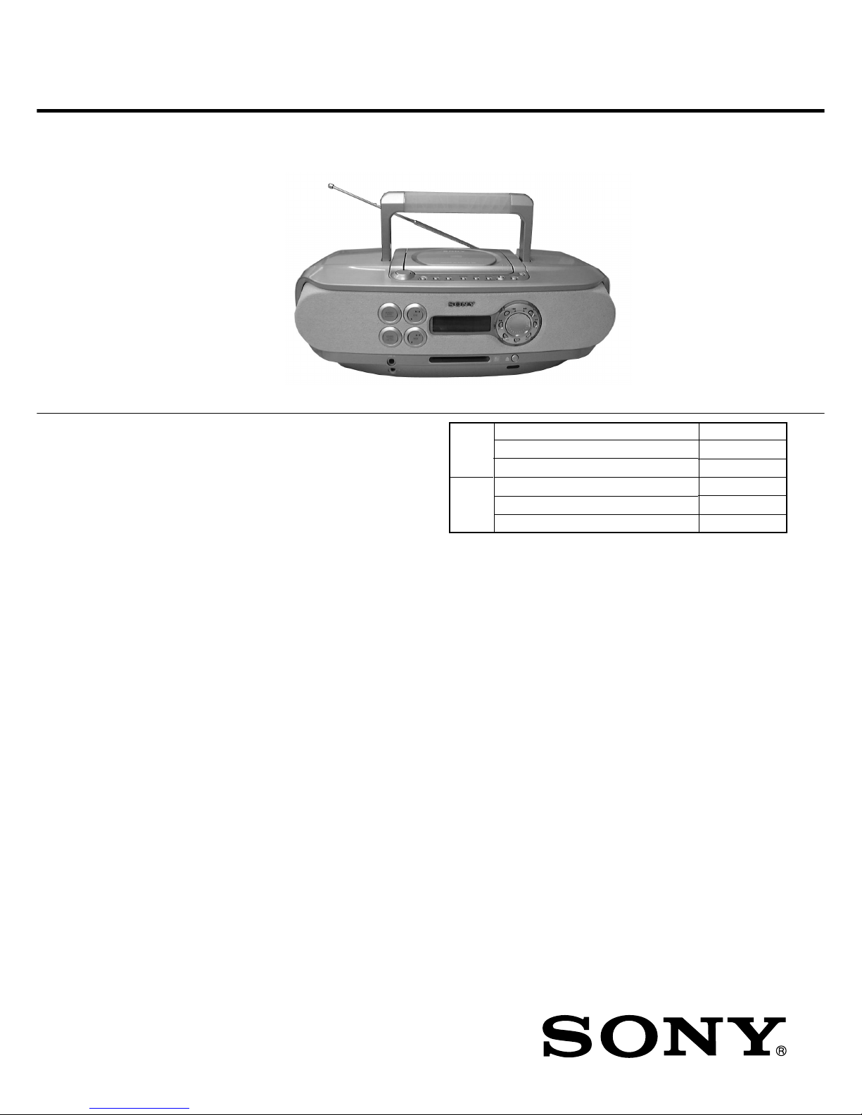
Sony ZS-M30 User manual

Ver 1.1 2001.04
Model Name Using Similar Mechanism
CD Mechanism Type
Optical Pick-up Name
Model Name Using Similar Mechanism
MD Mechanism Type
Optical Pick-up Name
ZS-M30
SERVICE MANUAL
PERSONAL MINIDISC SYSTEM
SPECIFICATIONS
AEP Model
UK Model
Australian Model
US and foreign patents licensed from Dolby
Laboratories Licensing Corporation
CD player section
System
Compact disc digital audio system
Laser diode properties
Material: GaAlAs
Wave length: 785 nm
Emission duration: Continuous
Laser output: Less than 44.6 µW
(This output is the value measured at a distance of about 200 mm
from the objective lens surface on the optical pick-up block with 7
mm aperture.)
Spindle speed
200 r/min (rpm) to 500 r/min (rpm) (CLV)
Number of programme positions
2
Frequency response
20 - 20 000 Hz +1/–2 dB
Wow and flutter
Below measurable limit
Radio section
Frequency range
FM: 87.5 - 108 MHz
MW:531 - 1,602 kHz (9 kHz step)
530 - 1,610 kHz (10 kHz step)
LW: 153 - 279 kHz
IF FM: 10.7 MHz
MW/LW: 450 kHz
Aerials
FM: Telescopic aerial
MW/LW: External aerial terminals
MD player section
System
Minidisc digital audio system
Disc
MiniDisc
Laser diode properties
Material: GaAlAs
Wave length: 785 nm
Emission duration: Continuous
Laser output: Less than 44.6 µW
(This output is the value measured at a distance of about 200 mm
from the objective lens surface on the optical pick-up block with 7
mm aperture.)
Recording/playback time
Stereo recording:
Maximum 80 minutes (with MDW-80)
Monaural recording:
Maximum 160 minutes (with MDW-80)
Revolutions
400 rpm to 900 rpm (CLV)
Error correction
Advanced Cross Interleave Reed Solomon Code (ACIRC)
Sampling frequency
44.1 kHz
Coding
Adaptive Transform Acoustic Coding (ATRAC)
9-873-011-12
2001D0200-1
© 2001.4
Sony Corporation
Personal Audio Company
Shinagawa Tec Service Manual Production Group
NEW
KSM-213CDP
KSS-213C
NEW
MT-ZSM30-168
KMS-260B
CD
Section
MD
Section

2
ZS-M30
Modulation system
EFM (Eight-to-Fourteen Modulation)
Number of programme positions
2 stereo programme positions
Frequency response
20 - 20,000 Hz +1/–2 dB
Signal-to-noise ratio
Over 80 dB (during playback)
Wow and flutter
Below measurable limit
General
Speaker
Full-range: 8 cm (3 1 ⁄4 in.) dia., 4 Ωcone type (2)
Panorama sound: 5 cm (2 in.) dia., 12 Ωcone type (2)
Inputs
LINE IN (stereo minijack): Sensitivity 436 mV/870 mV
Outputs
Headphones jack (stereo minijack) (1):
For 32 Ωimpedance headphones
Maximum power output
Full-range: 8 W
Panorama sound: 3.4 W
Specifications ........................................................................... 1
1. SERVICING NOTE
1-1. Notes on Handling the Optical Pick-up Block or
Base Unit ............................................................................ 3
1-2. Notes on Laser Diode Emission Check .............................. 3
1-3. Notes on Chip Component Replacement ........................... 3
1-4. Flexible Circuit Board Repairing ....................................... 3
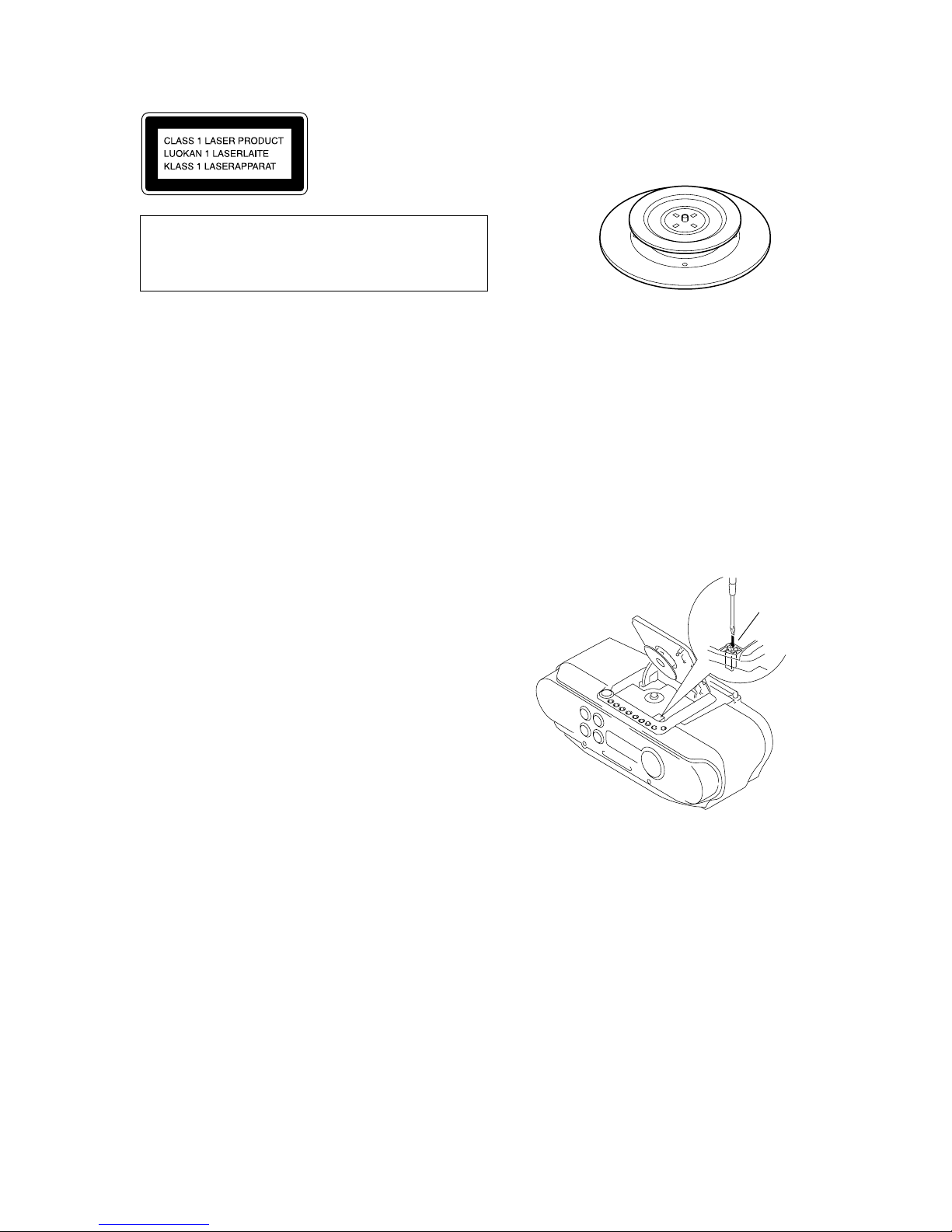
1-5. Chuck Plate Jig on Repairing ............................................. 3
1-6. Checking the Laser Diode and Focus Search Operation .... 3
1-7. Checks Prior to Parts Replacement and Adjustments
(for MD Section) ............................................................... 4
2. GENERAL
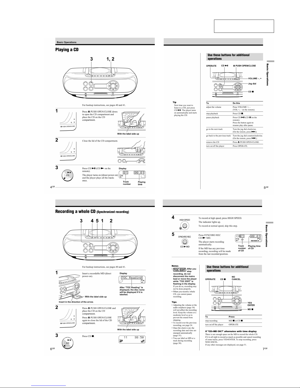
Playing a CD ...................................................................... 5
Recording a Whole CD (Synchronized Recording) ........... 5
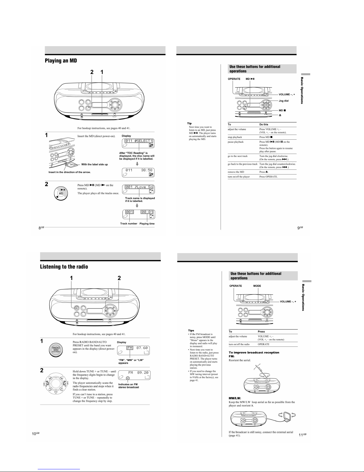
Playing an MD ................................................................... 6
Listening to the Radio ........................................................ 6
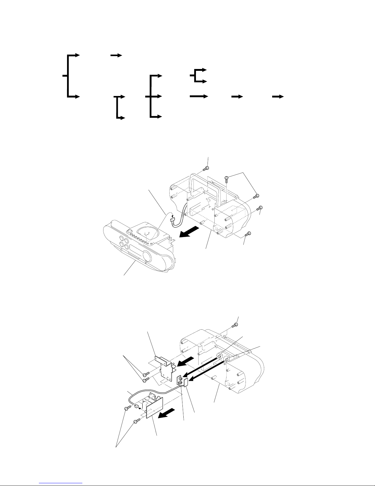
3. DISASSEMBLY
3-1. Cabinet (Rear), Cabinet (Front) ......................................... 7
3-2. BATT (B) Board, BATT (A) Board, Power Board ............. 7
3-3. Cabinet (Upper) ASSY ....................................................... 8
3-4. Main Board, LCD Board .................................................... 8
3-5. CD Board ........................................................................... 9
3-6. Top Board ........................................................................... 9
3-7. Tuner Board ........................................................................ 9
3-8. MD Block ASSY .............................................................. 10
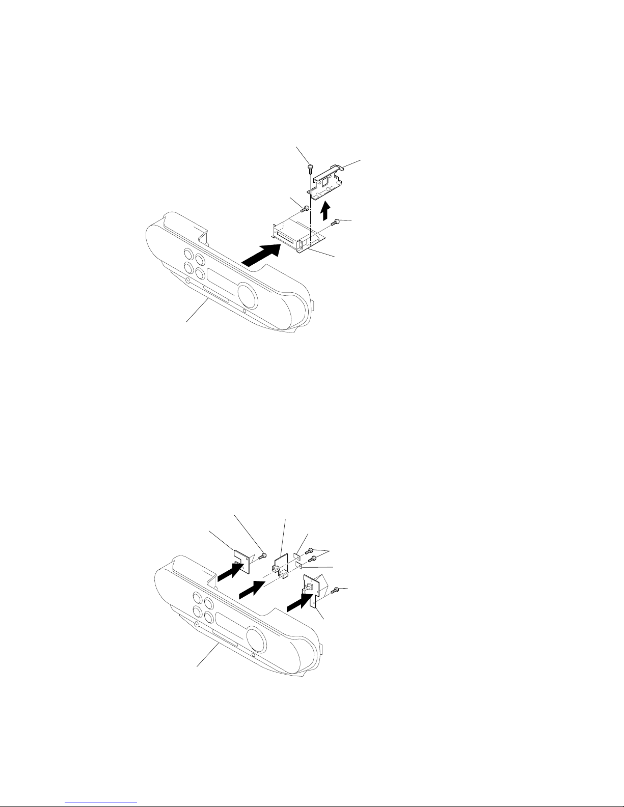
3-9. SW (L) Board, Jack Board, SW (R) Board ...................... 10
3-10. MD Board ...................................................................... 11
3-11. REC Board, DETECT Board ......................................... 11
3-12. Over Write Head (HR901), MD Optical Pick-up,
D SW Board ................................................................... 12
4. TEST MODE
4-1. MD Section ...................................................................... 13
4-2. Section the Test Mode ...................................................... 13
4-3. Releasing the Test Mode .................................................. 13
4-4. Basic Operations of the Test Mode .................................. 13
4-5. Selecting the Test Mode ................................................... 14
4-6. Functions of Other Buttons .............................................. 16
4-7. Test Mode Displays .......................................................... 16
4-8. Meanings of Other Displays............................................. 16
TABLE OF CONTENTS
Power requirements
For personal minidisc system:
230 V AC, 50 Hz
For back-up memory:
4.5 V DC, 3 R6 (size AA) batteries
For remote control:
3 V DC, 2 R6 (size AA) batteries
Power consumption
26 W
Dimensions (incl.projecting parts)
approx. 475 X165.5 X249 mm (w/h/d)
(18 3/4 X6 5 ⁄8 X9 7/8 inches )
Mass
approx. 4.6 kg (10 lb. 2 oz)
Supplied accessories
Mains lead (1)
Remote control (1)
MW/LW loop aerial (1)
AV connecting cord (1)
Audio connecting cord (1)
Design and specifications are subject to change without
notice.
5. ELECTRICAL ADJUSTMENT
5-1. Tuner Section ................................................................... 17
5-2. MD section ....................................................................... 19
5-3. CD section ........................................................................ 25
6. DIAGRAMS
6-1. IC Pin Function Descriptions ........................................... 28
6-2. Block Diagrams (1/4) ....................................................... 37
6-3. Block Diagrams (2/4) ....................................................... 38
6-4. Block Diagrams (3/4) ....................................................... 39
6-5. Block Diagrams (4/4) ....................................................... 40
6-6. Printed Wiring Boards -Main Section- ............................. 41
6-7. Schematic Diagram -Main Section (1/3)- ........................ 42
6-8. Schematic Diagram -Main Section (2/3)- ........................ 43
6-9. Schematic Diagram -Main Section (3/3)- ........................ 44
6-10. Printed Wiring Boards -Power Section- ......................... 45
6-11. Printed Wiring Boards -Tuner Section- .......................... 46
6-12. Schematic Diagram -Tuner Section- .............................. 47
6-13. Printed Wiring Boards -Control Section- ....................... 48
6-14. Schematic Diagram -Control Section- ........................... 49
6-15. Printed Wiring Boards -CD Section- .............................. 50
6-16. Schematic Diagram -CD Section- .................................. 51
6-17. Printed Wiring Boards -MD Section- ............................. 52
6-18. Schematic Diagram -MD Section (1/2)- ........................ 53
6-19. Schematic Diagram -MD Section (2/2)- ........................ 54
7. EXPLODED VIEWS
7-1. Rear Cabinet Section ........................................................ 64
7-2. Front Cabinet Section ....................................................... 65
7-3. Upper Cabinet Section ..................................................... 66
7-4. Optical Pick-up Section.................................................... 67
7-5. MD Section -1 .................................................................. 68
7-6. MD Section -2 .................................................................. 69
8. ELECTRICAL PARTS LIST .................................... 70

3
ZS-M30
1-1. NOTES ON HANDLING THE OPTICAL PICK-UP
BLOCK OR BASE UNIT
The laser diode in the optical pick-up block may suffer electro-
static break-down because of the potential difference generated
by the charged electrostatic load, etc. on clothing and the human
body.
During repair, pay attention to electrostatic break-down and also
use the procedure in the printed matter which is included in the
repair parts.
The flexible board is easily damaged and should be handled
with care.
1-2. NOTES ON LASER DIODE EMISSION CHECK
The laser beam on this model is concentrated so as to be focused
on the disc reflective surface by the objective lens in the optical
pick-up block. Therefore, when checking the laser diode emis-
sion,observe from more than 30 cm away from the objectivelens.
1-3. NOTES ON CHIP COMPONENT REPLACEMENT
• Never reuse a disconnected chip component.
• Notice that the minus side of a tantalum capacitor may be dam-
aged by heat.
1-4. FLEXIBLE CIRCUIT BOARD REPAIRING
• Keep the temperature of the soldering iron around 270 °C dur-
ing repairing.
• Do not touch the soldering iron on the same conductor of the
circuit board (within 3 times).
• Be careful not to apply force on the conductor when soldering
or unsoldering.
SAFETY-RELATED COMPONENT WARNING!!
COMPONENTS IDENTIFIED BY MARK 0OR DOTTED
LINE
WITH MARK 0ON THE SCHEMATIC DIAGRAMS AND IN
THE PARTS LIST ARE CRITICAL TO SAFE OPERATION.
REPLACE THESE COMPONENTS WITH SONY PARTS
WHOSE
PART NUMBERS APPEAR AS SHOWN IN THIS MANUAL
OR IN SUPPLEMENTS PUBLISHED BY SONY.
1-6. CHECKING THE LASER DIODE AND FOCUS
SEARCH OPERATION
1. Turn on the POWER and open the CD cover.
2. As shown below, push S701 (CD DOOR) with a screwdriver or
other tool.
3. Press the CD button.
4. Check the objective lens to make sure that the laser diode is
emitting light. If not so, the auto power control circuit or
optical pickup would be damaged.
Verify that the objective lens moves vertically three times for
focus search.
This Compact Disc player
is classified as a CLASS 1
LASER product.
The CLASS 1 LASER
PRODUCT label is located
on the bottom exterior.
CAUTION
Use of controls or adjustments or performance of proce-
duresother than those specified herein may result in haz-
ardous radiation exposure.
1-5. CHUCK PLATE JIG ON REPAIRING
On repairing CD section, playing a disc without the CD lid, use
Chuck Plate Jig.
• Code number of Chuck Plate Jig: X-4918-255-1
Insert a precision
screw driver and push
SWITCH (S701)
SECTION 1
SERVICE NOTE

4
ZS-M30
1-7. CHECKS PRIOR TO PARTS REPLACEMENT AND ADJUSTMENTS (FOR MD SECTION)
Before performing repairs, perform the following checks to determine the faulty locations up to a certain extent.
Details of the procedures are described in “5 Electrical Adjustments”
Laser power check
Criteria for Determination
(Unsatisfactory if specified value is not satisfied)
Note:
The criteria for determination above is intended merely to determine if satisfactory or not, and does not serve as the specified value for
adjustments.
When performing adjustments, use the specified values for adjustments.
Measure if unsatisfactory:
• Clean the optical pick-up
• Adjust again
• Replace the optical pick-up
• 0.9 mW power
Specified value : 0.80 to 0.96 mW
• 7.0 mW power
Specified value : 6.8 to 7.2 mW
lop (at 7mW)
• Labeled on the optical pickup
Iop value ±10%
• Replace the optical pick-up
If always unsatisfactory:
• Replace the overwrite head
• Check for disconnection of the circuits around the
overwrite head
If occasionally unsatisfactory:
• Check if the overwrite head is distorted
• Check the mechanism around the sled
• Error rate check
Specified value : For points a and b
C1 error : About 200
ADER : Below 2
Point C
C1 error :Below 50
AD error :Below 2
• Error rate check
Specified value:
a. When using test disc (MDW-74/AU-1)
C1 error : Below 80
ADER : Below 2
b. When using check disc (TDYS-1)
C1 error : Below 50
• CPLAY error rate check
Specified value:
C1 error : Below 80
ADER : Below 2
• Replace the optical pick-up
Focus power check
C PLAY check
Self-recording/playback
check

5
ZS-M30
SECTION 2
GENERAL This section is extracted from
instruction manual.

6
ZS-M30

7
ZS-M30
SECTION 3
DISASSEMBLY
Note : Follow the disassembly procedure in the numerical order given.
3-1. CABINET (REAR), CABINET (FRONT)
3-2. BATT (B) BOARD, BATT (A) BOARD, POWER BOARD
rThe equipment can be removed using the following procedure.
Set
Cabinet (rear)
Cabinet (front)
BATT (B) board, BATT (A) board, power board
Cabinet
(upper)
ASSY
Main board,
LCD board
SW (L) board,
jack board,
SW (R) board
REC board,
detect board
Over write head (HR901),
MD optical pick-up,
D SW board
MD block
ASSY
CD board
MD board
TOP board
Tuner
board
4
2
7
9
Cabinet (rear)
BATT (A) board
Chissis, transformer
BATT (B) board
Power board
5
Screws (+BVTP 3 X 12) (silver)
8
Screws (+BVTP 3 X 10)
6
Screws (+BVTP 3 X 10)
0
CN902
1
Claw
3
Claw
4
Main board
CN801
Cabinet (front)
Cabinet (rear)
2
Screws
(+BVTP 3 X 12) (silver
)
2
Screws
(+BVTP 3 X 12) (silver)
1
Screws (+BVTP 3 X 14)
1
Screws
(+BVTP 3 X 14)
3

8
ZS-M30
3-3. CABINET (UPPER) ASSY
3-4. MAIN BOARD, LCD BOARD
9
Cabinet (front)
Cabinet (upper) ASSY
8
Main board
(CN303)
7
Main board
(CN302)
6
Main board
(CN301)
2
CN810
1
Screws (+BVTP 3 X 10
)
4
CD board (CN703)
5
Wire,parallel (22 core)
Main board (CN807)
0
Wire,parallel (8 core)
SW (R) board (CN402)
3
Tuner board
(CN1)
5
8
LCD1
Cabinet (upper) ASSY
6
LCD board (CN404)
0
LCD board
Main board
7
Screws (+BVTP 3 X 10)
4
Screws (+BVTP 3 X 10
)
4
Screws (+BVTP 3 X 10)
9
Remove solder (7 places)
2
Wire,parallel (19 core)
Main board (CN808)
1
Wire,parallel (6 core)
Main board (CN803)
3
Main board (CN805)

9
ZS-M30
3-5. CD BOARD
3-6. TOP BOARD
CD board
Cabinet (upper) ASSY
4
1
Screw (+P 2 X 6)
3
Remove solder
(4 places)
2
Wire,Parallel (16 core
)
(CN701)
Top board
Cabinet (upper) ASSY
1
Screws (+BVTP 2.6 X 10)
2
3-7. TUNER BOARD
Tuner board
Cabinet (front)
1
Screws (+BVTP 3 X 10
)
2

10
ZS-M30
3-9. SW (L) BOARD, JACK BOARD, SW (R) BOARD
3-8. MD BLOCK ASSY
Cabinet (front)
SW (L) board
6
SW (R) board
Jack board
Retainer (A)
Retainer (B)
2
1
Screws (+BVTP 2.6 X 10)
3
Screws (+BVTP 3 X 10)
5
Screws (+BVTP 2.6 X 10
)
4
MD block ASSY
(MT-ZSM30-168)
Chassis (TU)
Cabinet (front)
1
Screws (+BVTP3 X10
)
1
Screws (+BVTP 3 X10)
3
Screws (+BVTT 2.6 X 6)
4
2

11
ZS-M30
3-10. MD BOARD
3-11. REC BOARD, DETECT BOARD
REC board
Chassis
3
DETECT board
7
Slider
4
Move slider away from pin.
8
Remove solder
(2 places)
2
Claws
2
Claw
1
Over write head flexible board
(CN504)
5
6
Claws
MT-ZSM30-168
Case (MD upper) shield
Case (MD lower) shield
MD board
2
qs
CN601 (2pin)
7
Screws (+P 2.6 X 2.5)
4
Screws, MD fitting
4
Screws, MD fitting
0
Op flexible board
8
Claw
8
Claw
8
Claw
1
Screws (+BVTP 2.6 X 5)
5
9
6
Wire,parallel (9 core)
REC board (CN505)
qa
Wire,Parallel (7 core)
3
Wire,parallel (22 core)
Main board (CN807)

12
ZS-M30
Over write head
(HR901)
3
MD optical pick-up
(KMS-260B)
4
Chassis
1
Screw (+P 1.7X2.5)
6
D SW board
5
Screws (1.4 X 2)
2
Screws (+P 1.4 X 3.5
)
3-12. OVER WRITE HEAD (HR901), MD OPTICAL PICK-UP, D SW BOARD

13
ZS-M30
SECTION 4
TEST MODE
Refer to “5. ELECTRICAL ADJUSTMENT” for the test mode of CD section.
4-1. MD SECTION
1. PRECAUTIONS FOR USE OF TEST MODE
• As loading related operations will be performed regardless of the test mode operations being performed, be sure to check that the disc is
stopped before setting and removing it.
Even if the Z (MD EJECT) button is pressed while the disc is rotating during continuous playback, continuous recording, etc., the disc
will not stop rotating.
Therefore, it will be ejected while rotating.
Be sure to press the Z(MD EJECT) button after pressing the NO/CANCEL button and the rotation of disc is stopped.
1-1. Recording laser emission mode and operating buttons
• Continuous recording mode (CREC MODE)
• Laser power check mode (LDPWR CHECK)
• Laser power adjustment mode (LDPWR ADJUST)
• When pressing the YES/ENTER button.
4-2. SETTING THE TEST MODE
1. Set to standby state.
2. Press and hold the YES/ENTER button then press MD u t x t u t x .
4-3. RELEASING THE TEST MODE
Remove the power cord to release the test mode.
4-4. BASIC OPERATIONS OF THE TEST MODE
All operations are performed with the following buttons: jogdial . , >, YES/ENTER and NO/CANSEL .
The functions of these buttons are as follows.
JOG ( > ) Proceeds the parameter/mode change.
JOG ( . ) Returns to the parameter/mode change.
YES/ENTER Goes ahead. Determines the setting/selection.
NO/CANCEL Suspends.
Function name Function

14
ZS-M30
•When selecting test mode, usually the message “TEMP ADJUST” appears. In two rare cases, however, another message may be shown.
1. After conclusion of automatic temperature compensation (starting from display “TEMP = 00”), the message “Disc Insert” appears.
2. The message “Disc Insert” is displayed right form the start.
In both cases press the YES/ENTER button while holding the EDIT button, thus displaying “TEMP ADJUST” and entering
normal test mode.
In order to cause “TEMP ADJUST” to be displayed whenever test mode is selected, execute the following steps.
1. Rotate the jog dial until “EEP MODE” is shown.
2. Press the YES/ENTER button to display “EEP READ”.
3. Press the YES/ENTER button to display “EEP XXXX”.
(The first two “X”-marks represent the address, the latter two the value).
4. Rotate the jog dial to set the address to 15.
5. Press the YES/ENTER button while holding the EDIT button.
6. Confirm that the display shows “EEP15XX >XX”.
7. Rotate the jog dial to set the value after the “>”-mark to FF.
8. Press the YES/ENTER button.
9. Confirm that the display shows “Complete”.
10.After that, confirm that the display turns to “EEP READ”.
11.Press the YES/ENTER button.
12.Confirm that the display shows “EEP15FF”.
13.Press the NO/CANCEL button.
4-5. SELECTING THE TEST MODE
There are 9 types of test modes as shown below. The groups can be switched by turn the jog dial. After selecting the
group to be used, press the YES/ENTER button. After setting a certain group, turn the jog dial between these modes.
• For details of each adjustment mode, refer to “5. Electrical Adjustments”.
• If a different mode has been selected by mistake, press the NO/CANCEL button to release that mode.
• EEP MODE is not used for servicing and therefore are not described in detail. If these modes are set accidentally, press the NO/CANCEL
button to release the mode immediately. Be especially careful this mode will overwrite the non-volatile memory and reset it, and as a
result, the unit will not operate normally.
TEMP ADJUST Temperature compensation offset adjustment
LDPWR ADJUST Laser power adjustment
LDPWR CHECK Laser power check
LOAD CHECK load check
S CURVE CHECK S curve check
EFBAL ADJUST EF balance adjustment
FBIAS ADJUST Focus bias adjustment
FBIAS CHECK Focus bias check
CPLAY MODE Continuous playback mode
CREC MODE Continuous recording mode
DETRK CHECK Detrack check
LOAD AGING Load aging
EEP MODE Non-volatile memory control
Display Contents

15
ZS-M30
4-5-1. Operating the Continuous Playback Mode
1. Entering the continuous playback mode
1Set the disc in the unit. (Whichever recordable discs or discs for playback only are available)
2Potate the jog dial and display “CPLAY MODE”.
3Press the YES/ENTER button to change the display to “CPLAY MID”.
4When access completes, the display changes to “C1 = AD = ”.
Note: The numbers “ ” displayed show you error rates and ADER.
2. Changing the parts to be played back
1Press the YES/ENTER button during continuous playback to change the display as below.
CPLAY MID CPLAY OUT CPLAY IN
When pressed another time, the parts to be played back can be moved.
2When access completes, the display changes to “C1 = AD = ”.
Note: The numbers “ ” displayed show you error rates and ADER.
3. Ending the continuous playback mode
1Press the NO/CANCEL button. The display will change to “CPLAY MODE”.
2Press the Z (MD) button and take out the disc.
Note: The playback start addresses for IN, MID, and OUT are as follows.
IN : 40h cluster
MID : 300h cluster
OUT: 700h cluster
4-5-2. Operating the Continuous Recording Mode (Use only when performing self-recording/palyback check)
1. Entering the continuous recording mode
1Set a recordable disc in the unit.
2Rotate the jog dial and display “CRDE MODE”.
3Press the YES/ENTER button to change the display to “CREC MID”.
4When access completes, the display changes to “CREC ( )” and “REC ” lights up.
Note: The numbers “ ” displayed shows you the recording position addresses.
2. Changing the parts to be recorded
1When the YES/ENTER button is pressed during continuous recording, the display changes as below.
When pressed another time, the parts to be recorded can be changed. “REC ” goes off.
2When access completes, the display changes to “CREC ( )” and “REC ” lights up.
Note: The numbers “ ” displayed shows you the recording position addresses.
3. Ending the continuous recording mode
1Press the NO/CANCEL button. The display changes to “CREC MODE” and “REC ” goes off.
2Press the Z (MD) button and take out the disc.
Note 1: The recording start addresses for IN, MID, and OUT are as follows.
IN : 40h cluster
MID : 300h cluster
OUT: 700h cluster
Note 2: The NO/CANCEL button can be used to stop recording anytime.
Note 3: Do not perform continuous recording for long periods of time above 5 minutes.
Note 4: During continuous recording, be careful not to apply vibration.
4-5-3. Non-storage memory mode (EEP mode)
This is the mode to read write the contents of the non-volatile storage memory.
This mode is not used for servicing.
If you accidentally enter this mode, exit immediately by pressing the NO/CANCEL button.
CREC MID CREC OUT CREC IN

16
ZS-M30
SHUF
PGM
During continuous playback (CLV: ON)
Tracking servo OFF
STOP (CLV: OFF)
Tracking servo ON
Recording mode OFF
Display Contents When Lit When Off
4-8.MEANINGS OF OTHER DISPLAYS
Contents
TOC EDIT
TRACK
TIMER
MONO
REC Recording mode ON
ABCD adjustment completed
Pit
CLV-S
FCS/TRK/AUTO GAIN successful
Groove
CLV-A
FCS successful, TRK unsuccessful
4-7. TEST MODE DISPLAYS
Each time the DISPLAY button is pressed, the display changes in the following order.
1. Mode display
Displays “TEMP ADJUST”, “CPLAYMODE”, etc.
2. Error rate display
Displays the error rate in the following way.
C1 = AD =
C1 = Indicates the C1 error.
AD = Indicates ADER.
3. Address display
The address is displayed as follows. (MO: recordable disc, CD: playback only disc)
Press the REPEAT buttons at the same time to switches between the groove display
and pit display.
h = s = (MO pit and CD)
h = a = (MO groove)
h = Indicates the header address.
s = Indicates the SUBQ address.
a = Indicates the ADIP address.
Note: “–” is displayed when servo is not imposed.
4. Auto gain display (Not used in servicing)
The auto gain is displayed as follows.
AG F = T =
5. IVR display (Not used in servicing)
The IVR is displayed as follows.
[ ][ ][ ]
Function Contents
REC/REC MODE
Sets continuous playback when pressed in the STOP state. When pressed during continuous
playback, the tracking servo turns ON/OFF.
4-6. FUNCTIONS OF OTHER BUTTONS
u (MD)
x(MD)
M
m
DISPLAY
Z(MD)
When pressed during continuous playback, switches between recording start stop.
Stops continuous playback and continuous recording.
The sled moves to the outer circumference only when this is pressed.
The sled moves to the inner circumference only when this is pressed.
Switches the displayed contents each time the button is pressed
Ejects the disc
Mode display
Error rate display
Address display
Auto gain display
(Not used in servicing)
IVR display
(Not used in servicing)

17
ZS-M30
TUNER BOARD
C27
C10
R5
JC3
C12
R28
C44
Q3
C45
C43
C51
C5
R7
R4
D2
C6
R2
R3
C7
R32
Q2
Q4
R6
C8
C46
C47
C4
L7
C54
C11
R13 C26 R14
C9
R30
D4
D8
D9
D5
R31
D6
D7
9
JW2
JW7
CT4
JW6
8
D3
L4
L2
JW10
L5
JW5
Q1
FL1
CT3
L3
CT2
JW4
JW3
JW1
+
—
Digital
JW4
(VT)
100K
Ω
voltmeter
SECTION 5
ELECTRICAL ADJUSTMENTS
RADIO BAND button : MW or LW
Volume : MIN
5-1.TUNER SECTION
AM Section
FM Section
RADIO BAND button : FM
Volume : MIN
Put the lead-wire
antenna close to
the supplisd MW/L
W
loop antenna.
AM RF signal
generator
30% amplitude modulation by 400Hz
signal.
Output level : as low as possible
telescopi
c
antenna
terminal
FM RF signal
generator
22.5kHz frequency deviation by
400Hz signal.
Output level : as low as possible
0.01 uF
Adjustment Location : Tuner board (See page 18)
• Repeat the procedures in each adjustment several times, and the
frequency coverage and tracking adjustments should be finally
done by the trimmer capacitors.
AM IF ADJUSTMENT
Adjust for a maximum reading on level meter.
T1 450kHz
MW FREQUENCY COVERAGE ADJUSTMENT
Adjust part Frequency display
L5 531kHz
Confirmation 1,611kHz
reading on digital
voltmeter.
Adjustment value: 1.0V
Standaed value: 0.7 to 1.3V
5.1 to 5.9V
MW TRACKING ADJUSTMENT
Adjust for a maximum reading on level meter.
L 3 621kHz
CT2 1,404kHz
LW FREQUENCY COVERAGE ADJUSTMENT
Adjust part Frequency display
CT4 279kHz Adjustment value: 5.4 to 6.0V
Confirmation 153kHz 0.4 to 1.1V
Frequency Coverage Adjustment
Connect Location :
reading on digital
voltmeter
LW TRACKING ADJUSTMENT
Adjust for a maximum reading on level meter.
L 4 162kHz
CT3 261kHz
FM FREQUENCY COVERAGE ADJUSTMENT
Adjust part Frequency display
Confirmation 87.5kHz 1.4 to 2.4V
Confirmation 108kHz 2.7 to 3.7V
reading on digital
voltmeter
FM IF ADJUSTMENT
Adjust for a maximum reading on level meter.
L6 10.7MHz
FM TRACKING ADJUSTMENT
Adjust for a maximum reading on level meter.
L1 87.5MHz
CT1 108MHz
47K
Ω
level mete
r
set
LINE OUT
+
–
(SIDE B)

18
ZS-M30
L5 : MW Frequency
Coverage Adjustmen
t
CT4 : LW Frequency Coverage Adjustment
T1 : AM IF Adjustment
L6 : FM IF Adjustment
L3 : MW Tracking Adjustment
CT2 : MW Tracking Adjustment
CT1 : FM Tracking Adjustment
L4 : LW Tracking Adjustment
CT3 : LW Tracking Adjustment
L1 : FM Tracking Adjustment
[TUNER BOARD]
(Component side)
Adjustment Location:

19
ZS-M30
5-2. MD SECTION
1. PARTS REPLACEMENT AND ADJUSTMENT
• Check and adjust the mechanism deck as follows.
The procedure changes according to the part replaced.
• Laser power check
• Focus bias check
• C PLAY check
• Self-recording/playback check
Parts Replacement and Repair
NG
Has the OWH been replaced?
NO
OK
NO
NO
NO
Has OP, IC603, IC502, or
IC504 been replaced?
YES
YES
Initial setting of the adjustment value
Has OP or IC603 been replaced?
YES
IOP information recording
(IOP value labeled on OP)
Has IC603 or D501
been replaced?
YES
Temperature compensation offset adjustment
• Laser power adjustment
• EF balance adjustment
• Focus bias adjustment
• Error rate adjustment
• Focus bias check
• Auto gain adjustment
Check the sled and spindle
mechanisms.
Other causes can be suspected.
• Abbreviation
OP : Optical pick-up
OWH : Overwrite head

20
ZS-M30
2. PRECAUTIONS FOR CHECKING LASER DIODE
EMISSION
To check the emission of the laser diode during adjustments, never
view directly from the top as this may lose your eye-sight.
3. PRECAUTIONS FOR USE OF OPTICAL PICK-UP
(KMS-260B)
As the laser diode in the optical pick-up is easily damaged by static
electricity, solder the laser tap of the flexible board when using it.
Before disconnecting the connector, desolder first. Before connect-
ingthe connector, be careful not to remove the solder. Also take
adequate measures to prevent damage by static electricity. Handle
the flexible board with care as it breaks easily.
4. PRECAUTIONS FOR ADJUSTMENTS
1. When replacing the following parts, perform the adjustments
and checks with in the order shown in the following table.
2. Set the test mode when performing adjustments.
After completing the adjustments, release the test mode.
Perform the adjustments and checks in “group S” of the test
mode.
3. Perform the adjustments to be needed in the order shown.
4. Use the following tools and measuring device.
• Check Disc (MD) TDYS-1
(Part No. 4-963-646-01)
• Test Disc (MDW-74/AU-1) (Part No. 8-892-341-41)
• Laser power meter LPM-8001 (Part No. J-2501-046-A)
or MD Laser power meter 8010S (Part No. J-2501-145-A)
• Oscilloscope (Measure after performing CAL of prove)
• Digital voltmeter
• Thermometer
5. When observing several signals on the oscilloscope, etc., make
sure that VC and ground do not connect inside the oscilloscope.
(VC and ground will become short-circuited)
6. Using the above jig enables the waveform to be checked with-out
the need to solder.
(Refer to Service Note on page 3)
7. As the disc used will affect the adjustment results, make sure
that not dusts nor fingerprints are attached to it.
Laser Power Meter
When performing laser power checks and adjustment (electrical
adjustment), use of the new MD laser power meter 8010S (Part No.
J-2501-145-A) instead of the conventional laser power meter is con-
venient.
It sharply reduces the time and trouble to set the laser power meter
sensor onto the objective lens of optical pick-up.
5. CREATING CONTINUOUSLY-RECORDED DISC
* This disc is used in focus bias adjustment and error rate check.
The following describes how to create a continuous recording
disc.
1. Insert a disc (blank disc) commercially available.
2. Turn the JOG dial to display “CREC MODE”.
3. Press the YES/ENTER button again to display “CREC MID”.
Display “CREC (0300)” and start to recording.
4. Complete recording within 5 minutes.
5. Press the NO/CANCEL button and stop recording.
6. Press the Z (MD) button and remove the disc.
The above has been how to create a continuous recorded data for
the focus bias adjustment/check and MO error rate check.
Note:
• Be careful not to apply vibration during continuous recording.
flexible boar
d
laser tap
pick- up
Optical pick-up flexible board
2.Temperature
compensation
offset adjustment
1. Recording of IOP
information
(Value written in
the pick-up)
3.Laser power
adjustment
4.EF balance
adjustment
5.Focus bias
adjustment
6.Error rate check
Optical
Pick-up
BD Board
IC603 D501 IC502, IC504 IC506
Other manuals for ZS-M30
1
Table of contents
Other Sony Mini Disc Player manuals

Sony
Sony DS-JA555ES User manual

Sony
Sony MZ-R55 User manual

Sony
Sony MDS-JB930 User manual

Sony
Sony MDX-C7970/C7970R User manual

Sony
Sony MDS-JE700 - Mini Disc Player User manual

Sony
Sony MZ-E60 User manual

Sony
Sony MDX-65 User manual

Sony
Sony Hi-MD Walkman MZ-NH1 User manual

Sony
Sony MDS-PC3 User manual

Sony
Sony Walkman MZ-NF810CK User manual

Sony
Sony MDS-PC1 User manual

Sony
Sony MDS-PC3 User manual

Sony
Sony NET MD MDS-JB980 User manual

Sony
Sony MINIDISC ZS-M35 User manual

Sony
Sony MZ-E510 User manual

Sony
Sony Walkman MZ-E505 User manual

Sony
Sony MZ-E2 User manual

Sony
Sony MZ-N10 User manual

Sony
Sony MDS-B6P User manual

Sony
Sony Walkman MZ-E707 User manual