Features 7
High image-quality/high-resolution SXGA LCD
panel
An SXGA high-resolution (1280 × 1024 dots) panel and
high brightness/ultra-wide field of view technology
enable you to use the monitor under various lighting
conditions and in numerous ways (installing on wall,
using several monitors to view an image, and so on.).
Because a color filter with wide-color reproduction and
LCD materials with high response speed are used, the
motion picture of the video signal is displayed clearer.
This monitor also performs sampling of signals at high
frequencies and provides a high resolution of 700 TV
scanning lines or more during the RGB/COMPONENT
signal (480/60I, 575/50I) input.
Input
Accepts analog RGB input signals *1
Adopting the scan converter allows this monitor to
detect VGA, SVGA, XGA and SXGA analog RGB
signals input to the HD15 input connector.
Accepts DVI-D (digital) input signals *1
Adopting the scan converter allows this monitor to
detect VGA, SVGA, XGA and SXGA digital computer
signals input to the DVI input connector.
To view SXGA signals when the DVI input is selected,
use the cable within 3 m (118 1/8 inches) in length.
*1 For acceptable formats, refer to “About the preset signal”
on pages 29 and 30.
Optional slot for the video signal
Two optional input adaptors can be attached. The
composite, Y/C, component, analog RGB or SDI signal
can be input depending on the input connectors of the
board to be used.
Multi-format *2
NTSC or PAL color system or DTV format, such as
720P, 1080I, etc. can be selected automatically.
*2 For acceptable formats, refer to “Video signal formats” on
page 28.
External sync input
The unit can be operated on the sync signal supplied
from an external sync generator.
Functions
APA (Auto Pixel Alignment) function
You can display pictures from the HD 15 input
connector in the appropriate picture by simply pressing
the APA key.
Automatic termination (connector with
mark only)
The input connector is terminated internally at 75 ohms
when nothing has been connected to the output
connector. If a cable is connected to the output
connector, the internal terminal is automatically
released and the signals input to the input connector are
output to the output connector (loop-through).
Select color temperature and gamma mode
You can select the color temperature from among four
(HIGH, LOW, LOW2, LOW3) settings and gamma
mode from among five settings. You can also adjust the
color temperature to the appropriate setting in “USER”.
Aspect setting
You can set the monitor to 4:3 or 16:9 display mode
according to the input signal.
Scan function
You can select the display from among “NORMAL”,
“UNDER”, “OVER”, “FULL”, “ZOOM” and
“NATIVE” (1080I and 720P only)” except the HD 15
and DVI input signals.
Select language display
You can select your language for the display from seven
languages - English, German, French, Italian, Spanish,
Japanese and Chinese.
Power saving function
The monitor enters into power saving mode to reduce
the power consumption when no signal is input.
Key inhibit function
You can inhibit the key to prevent missing an operation.
User memory function
You can save the 20 picture settings with the name. The
user memory data can be saved or loaded between the
monitor and the equipment (PC, etc.) connected in
serial remote mode.
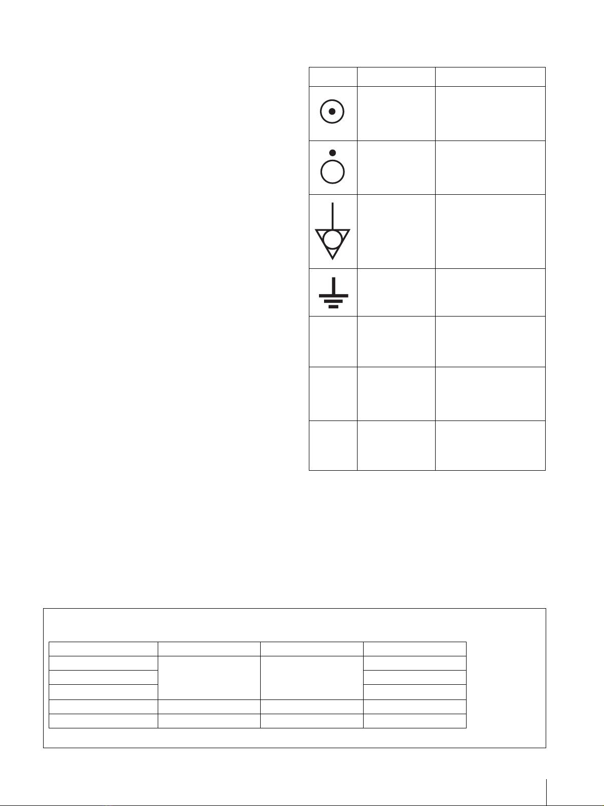
Two kinds of ground terminals
Two kinds of ground terminals are built into the monitor
to equal the electric potential.
External remote control function
You can directly select the input signal, aspect, etc. by
operating the connected equipment.
Other
Optional stand
It is more convenient to install the monitor on a desk by
using the optional stand (SU-560).