1 (E)
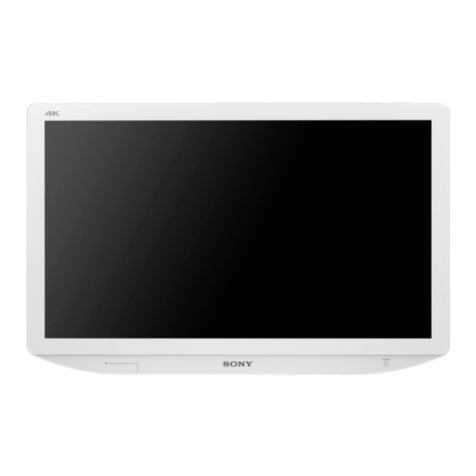
PVM-A250
Table of Contents
3. Troubleshooting
3-1. LED (Power Switch) on the Front Panel
Blinks in Red.............................................................3-1 (E)
3-1-1. Preparation.......................................................3-1 (E)
3-1-2. Setting of PC....................................................3-1 (E)
3-1-3. Connection with Monitor.................................3-2 (E)
3-1-4. Reading the Register........................................3-3 (E)
3-1-5. Check Method and Remedy............................. 3-4 (E)
3-2. LED on a QBC Board Lights .................................... 3-5 (E)
3-3. LED on a G2 Board Lights .......................................3-6 (E)
3-4. System Does Not Start ..............................................3-8 (E)
3-5. Abnormality Is Found in Control Operation.............3-9 (E)
4. Spare Parts
4-1. Notes on Repair Parts...................................................... 4-1
4-2. Exploded Views............................................................... 4-2
4-3. Packing Materials & Supplied Accessories................... 4-10
5. Block Diagrams
Overall............................................................................. 5-1
Manual Structure
Purpose of this manual............................................................ 2 (E)
Related manuals...................................................................... 2 (E)
Trademarks.............................................................................. 2 (E)
1. Service Overview
1-1. Appearance Figure ....................................................1-1 (E)
1-2. Board Location..........................................................1-1 (E)
1-3. Tighten Torque ..........................................................1-2 (E)
1-4. Disassembly ..............................................................1-3 (E)
1-4-1. Rear Cover ....................................................... 1-3 (E)
1-4-2. PWM Fan (Left)...............................................1-5 (E)
1-4-3. G2 Board..........................................................1-6 (E)
1-4-4. PWM Fan (Right) ............................................1-7 (E)
1-4-5. Bezel Assembly................................................1-8 (E)
1-4-6. H1 Board..........................................................1-9 (E)
1-4-7. Speaker...........................................................1-10 (E)
1-4-8. H2 Board........................................................ 1-11 (E)
1-4-9. OLED Module Assembly...............................1-12 (E)
1-5. Periodic Replacement Parts and Cleaning ..............1-13 (E)
1-5-1. Periodic Replacement Parts ........................... 1-13 (E)
1-5-2. Cleaning.........................................................1-13 (E)
1-6. Lead-free Solder......................................................1-13 (E)
2. Circuit Description
2-1. Board Configuration.................................................. 2-1 (E)
2-2. G2 Board ................................................................... 2-1 (E)
2-3. H1 Board ................................................................... 2-1 (E)
2-4. H2 Board ................................................................... 2-1 (E)
2-5. QBC Board................................................................2-2 (E)


