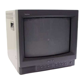
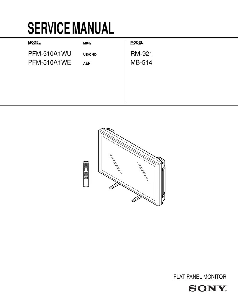
Sony Trinitron PVM-1271Q User manual

SERVICE MANUAL
October, 1984
US Model
Chassis No. SCC-611A-A
US Model
Canadian Model
Chassis No. SCC-585A-A
SPECIFICATIONS
Picture tube
Resolution
Color temperature
Color system PAL, SECAM, NTSC and NTSC4 43 systems,
switched automatically
Picture tube Trinitron tube
Approx. 33 cm (13 inches), 90 degree deflec-
tion, Super Fine Pitch 0.25 mm
(Approx. 31 cm picture measured diagonally)
Resolution RGB inputs :600 lines, 640 x200 dots
Composite input :550 lines
Color temperature PVM-1271Q: 9,300'’K
PVM-1371QM; 6,500OK
(Can be changed to either temperature by
an internal switch. For switching of the col-
or temperature, consult your authorized
Sony dealer.)
Frequency response 10 MHz (-3 dB, RGB)
5.5.MHZ (-3 dB, composite video)
Horizontal linearity ±8%
Vertical linearity ±5%
Line pull range Horizontal +500 Hz
Vertical sHz
Overscan of the picture
5%
Underscan of the picture
9%
Return loss 4MHz, 35 dB (LINE A, LINE B)
Zooming Within 2%
Convergence Central area 0.6 mm
Periphery 0.8 mm
Brightness More than 35 foot-lamberts
Horizontal linearity
Vertical linearity
Line pull range Outputs
Power requirements
Power consumption
Dimensions
Weight
VIDEO IN :BNC connector
VTR :8-pin connector, Pin No. 2(pin No. ^
6:ground) i
composite 1Vp-p +6 dB, sync negative,/
75 ohms and high impedance switchat/
AUDIO IN :minijack /
VTR :8-pin connector. Pin No. 1(pin 1/
5;ground) I
-5 dBs, high impedance
EXT SYNC IN :BNC connector
composite sync 2-8 Vp-p, negative,
75 ohms and high impedance switchable
RGB IN :BNC connector
0.7 Vp-p, ±6 dB, 75 ohms, non composite
AUDIO (RGB) IN :mini jack
-5 dBs, high impedance
CMPTR :25-pin' connector
For details, see “CMPTR connector”
VIDEO OUT :BNC connector
AUDIO OUT ;mini jack
Output level 1W
EXT SYNC OUT :BNC connector
RGB OUT :BNC connector
AUDIO (RGB) OUT :mini jack
Loop-through
PVM-1 271 Q:120 Vac, 50/60 Hz
PVM-1371QM: 220 -240 Vac, 50/60 Hz
PVM-1271Q: 105 W
PVM-1371QM; 90 W
Approx. 346 x330 x387 mm (w/h/d)
(13^8 X13 X15>/4 inches)
Approx. 14.5 kg (31 lb 15 oz)
TRINITRON®
COLOR VIDEO MONITOR
IK
MICROFILM

CMPTR connector (25-pin)
Pin assignment
7^
Pin No Signal Signal level
1*iBM select Highs*ate(5V): IBM mode
Low state :3Bit TTL
2High state (5 Vor open) :Audio inputs from pin 13.
'0 ;Audio inputs from the LINE AAUDIO IN jack
3H. sync or composite sync Negative polarity
When the high state is selected at pin 9
:
1Vp-p, 75-ohm terminated
When the iow state is selected at pin 9
:
TTL level
4
5
6
Blue input Positive polarity
When the high state is selected at nin g•
Green input terminated, non sync)
.1When the low state is selected at pin 9
:
Red input Digitai signal (TTL level)
7--12 Vpower supply 0.3 Amax
8-k 5Vpower supply 0.6 Amax
9* Analog/digital mode select High state (open) ;Analog signal (0.7 Vp-p)
Low state (ground) :Digital signal fnLJe^
Pin No. Signal level
10 RGB/NORMAL mode select High state (5 Vor open) :RGB inputs from amicrocomputer
ow state (ground) :Composite video inputs from the LINE AVIDEO IN connector
11 ^Negative polarity
TTL level
12 ®(5 Vor open) :Video inputs from amicrocomputer only
Low state (ground) :Composite video input from the LINE AVIDEO IN connector
During the low state, the video signal from the microcomputer is blanked and the
compos.te v,deo Signal from the LINE AVIDEO IN connector is supSposS over
the signai from the microcomouter uKCMniposeo over
13 -5 dB (100O/. modulation), input impedance more than 47 kohms
14
15-24
bX 1/IN 1mode sync switch High state (open) :Sync signal input from the CMPTR connector
Low state ;Sync signal input from the LINE AVIDEO IN connector
Ground —
25 *BM luminance signal Positive polarity
When the high state is selected at pin 1:TTL ievel
When the low state is selected at pin 1;Low state (oroundl
*Examples for microcomputer connections
^'^'''\^Pin No.
Microcomputer^\ 1925
SMC-70/SMC-70G —High state
iBM computer High state Low state iBM luminance signal
TTL 3BIT computer Low state Low state Low state
While the information given is true at the time of printing, small pro-
duction changes in the course of our company's policy of improve-
ment through research and design might not necessariiy be in-
dicated in the specifications. We would ask you to check with vour
appointed Sony dealer if clarification on any point is required.
i
I
-2—

SAFETY CHECK-OUT
PVM-12710\
After correcting the original service problem,
perform the following safety checks before releasing
the set to the customer:
1.Check the area of your repair for unsoldered or
poorly-soldered connections. Check the entire
board surface for solder splashes and bridges.
2. Check the interboard wiring to ensure that no
wires are “pinched” or contact high-wattage
resistors.
3. Check that all control knobs, shields, covers,
ground straps, and mounting hardware have
been replaced. Be absolutely certain that you
have replaced all the insulators.
4. Look for unauthorized replacement parts, par-
ticularly transistors, that were installed during a
previous repair. Point them out to the customer
and recommend their replacement.
5. Look for parts which, though functioning, show
obvious signs of deterioration. Point them out
to the customer and recommend their replace-
ment.
6. Check the line cord for cracks and abrasion.
Recommend the replacement of any such line
cord to the customer.
7. Check the condition of the monopole antenna
(if any).
Make sure the end is not broken off, and has
the plastic cap on it. Point out the danger of
impalement on abroken antenna to the
customer, and recommend the antenna’s
replacement.
8. Check the B+ and HV to see they are at the
values specified. Make sure your instruments
are accurate; be suspicious of your HV meter
if sets always have low HV.
9. Check the antenna terminals, metal trim,
“metallized” knobs, screws, and all other
exposed metal parts for AC leakage. Check
leakage as described below.
To Exposed Meta!
Parts on Set
0.15pF AC
voltmeter
10.75 V)
Earth Ground
\Fig. A. Using an AC voltmeter to check AC leakage.
LEAKAGE TEST
The AC leakage from any exposed metal part to
earth ground and from all exposed metal parts to any
exposed metal part having areturn to chassis, must
not exceed 0.5 mA (500 microampers). Leakage
current can be measured by any one of three
methods.
1.Acommercial leakage tester, such as the
Simpson 229 or RCA WT-540A. Follow the
manufacturers’ instructions to use these instru-
ments.
2. Abattery-operated AC milliammeter. The Data
Precision 245 digital multimeter is suitable for
this job.
3. Measuring the voltage drop across aresistor by
means of aVOM or battery-operated AC'volt-
meter. The “limit” indication is 0.75 V, so
analog meters must have an accurate low-
voltage scale. The Simpson 250 and Sanwa
SH-63Trd are examples of apassive VOM that
is suitable. Nearly all battery operated digital
multimeters that have a2V AC range are
suitable. (See Fig. A)
HOW TO FIND AGOOD EARTH GROUND
Acold-water pipe is guaranteed earth ground; the
cover-plate retaining screw on most AC outlet boxes is
also at earth ground. If the retaining screw is to be
used as your earth-^ound, verify that it is at ground
by measuring the resistance between it and acold-
water pipe with an ohmmeter. The reading should be
zero ohms. If acold-water pipe is not accessible,
connect a60—100 watts trouble light (not aneon
lamp) between the hot side of the receptacle and the
retaining screw. Try both slots, if necessary, to locate
the hot side of the line, the lamp should light at
normal brilliance if the screw is at ground potential.
(See Fig. B)
-3

/PVM-1271Q
TABLE OF CONTENTS
Section Title Page
1. GENERAL
1-1 .Features 5
1-2. Precautions 5
1-3. Location of Controls 6
1-4. Function of Controls 7
1-
5. System Connections 9
2. DISASSEMBLY
2-
1. Cabinet Ass’y Removal 12
2-2. BBoard Removal 12
2-3. Chassis Ass’y Removal 13
2-4. Fboard Removal (1)14
2-5. Fboard Removal (2) 14
2-
6. Picture Tube Removal 15
3. ADJUSTMENTS
3-
1. Setup Adjustments 16
3-1-1. Beam Landing 16
3-1-2. Convergence 17
3-1-3. Focus 17
3-1-4. White Balance 18
3-2. Safety Related Adjustments .- 20
Section Title Page
i3-3. Circuit Adjustments 23
3-3-1 .DBoard Adjustments 23
3-3-2. BBoard Adjustments 27
3-3-3. QBoard Adjustments 31
4. DIAGRAMS
4-1. Block Diagram 35
4-2. Circuit Boards Locating 38
4-3. Waveforms 39
4-4. Schematic Diagram 43
4-5. Printed Wiring Boards 51
BBoard 51,
DBoard 52
QBoard 54
HBoard 55
Cl Board 56
C2 Board 57
Fand F2 Boards 58
4-
6. Semiconductors 59
5. EXPLODED VIEWS
5-
1. Cabinet 60
5-2. Bezel 61
5-3. Chassis 62
6.
ELECTRICAL PARTS LIST
!
i
SAFETY-RELATED COMPONENT WARNING !!
COMPONENTS IDENTIFIED BY SHADING AND MARK
AON THE SCHEMATIC DIAGRAMS, EXPLODED
VIEWS AND IN THE PARTS LIST ARE CRITICAL TO
SAFE OPERATION. REPLACE THESE COMPONENTS
WITH SONY PARTS WHOSE PART NUMBERS APPEAR
AS SHOWN IN THIS MANUAL OR IN SUPPLEMENTS
PUBLISHED BY SONY. CIRCUIT ADJUSTMENTS
THAT ARE CRITICAL TO SAFE OPERATION ARE
IDENTIFIED IN THIS MANUAL. FOLLOW THESE PRO-
CEDURES WHENEVER CRITICAL COMPONENTS ARE
REPLACED OR IMPROPER OPERATION IS SUSPECTED.
ATTENTION AUX COMPOSANTS RELATIFS ALA
SECURITEI!
LES COMPOSANTS IDENTIFIES PAR UNE TRAME ET
PAR UNE MARQUE ASUR LES SCHEMAS DE PRINCIPE,
LES VUES EXPLOSEES ET LES LISTES DE PIECES
SONT D'UNE IMPORTANCE CRITIQUE POUR LA
SECURITE DU FONCTIONNEMENT. NE LES REM-
PLACER QUE PAR DES COMPOSANTS SONY DONT LE
NUMERO DE PIECE EST INDIQUE DANS LE PRESENT
MANUEL OU DANS DES SUPPLEMENTS PUBLIES PAR
SONY. LES REGLAGES DE CIRCUIT DONT L'lMPOR-
TANCE EST CRITIQUE POUR LA SECURITE DU
FONCTIONNEMENT SONT IDENTIFIES DANS LE
PRESENT MANUEL. SUIVRE CES PROCEDURES LORS
DE CHAQUE REMPLACEMENT DE COMPOSANTS
CRITIQUES, OU LORSQU'UN MAUVAIS FONCTIONNE-
MENT EST SUSPECTE.
-4-

SECTION 1
GENERAL
PVM-1271Q ^
1-2. PRECAUTIONS
1-1. FEATURES
High-resolution picture
The Super Fine Pitch Trinitron picture tube (0.25 mm aper-
ture grill) gives high resolution (composite: 550 lines,
RGB ;650 lines) picture. When used as acharacter display,
up to 2000 characters (80 characters/line x25 lines) can be
displayed with great clarity.
Analog/digital RGB input
Analog RGB and digital (TTL level) RGB input signals can be
fed to the RGB input connectors (BNC type and 25-pin multi
connectors), which allows amicrocomputer or adata infor-
mation system such as teletext, to be connected to this
monitor.
Receives 4TV broadcasting standards
This monitor can receive PAL, SECAM, NTSC and NTSC443
signals. The appropriate broadcasting standard is selected
automatically.
Colorpure Filter
When NTSC video signals are received, acolorpure filter ac-
tivates to increase the resolution about 35%, resulting in
fine picture detail without color spill or color noise.
Underscan mode
The signal normally scanned outside of the screen can be
monitored in the underscan mode.
Automatic frequency control
The incoming sync timing error compensation speed can be
set to fast or slow, according to the input signal. In the slow
mode, the jitter from avideo tape recorder can be easily
monitored.
Superimposition of apicture from amicrocomputer on apic-
ture from video equipment
When aSony SMC-70 or SMC-70G microcomputer, an
SMI-7073 superimposer and video equipment such as a
video disc player are used together with this monitor, apic-
ture from the microcomputer can be superimposed on apic-
ture from the video equipment.
*An NTSC443 system signal is obtained by playing back NTSC-recorded
video tapes with avideo tape recorder/player specially designed tor use with
this system.
On safety
•Check that the operating voltage of your unit is identical
with the voltage of your local power supply.
•Should any liquid or solid object fall into the cabinet,
unplug the unit and have it checked by qualified personnel
before operating it any further.
•Unplug the unit from the wall outlet if it is not to be used
for several days.
•To disconnect the ac power cord, pull it out by the plug.
Never pull the cord itself.
On installation
•Allow adequate air circulation to prevent internal heat
build-up.
Do not place the unit on surfaces (rugs, blankets, etc.) or
near materials (curtains, draperies) that may block the ven-
tilation holes.
•Do not install the unit in alocation near heat sources such
as radiators or air ducts, or in aplace subject to direct
sunlight, excessive dust, mechanical vibration or shock.
On cleaning
To keep the unit looking brand-new, periodically clean it
with asoft cloth. Stubborn stains may be removed with a
cloth lightly dampened with amild detergent solution. Never
use strong solvents such as thinner or benzine, or abrasive
cleansers since these will damage the cabinet. As asafety
precaution, unplug the unit before cleaning it.
On repacking
Do not throw away the carton and packing materials. They
make an ideal container in which to transport the unit. When
shipping the unit to another location, repack it as illustrated
on the carton.
If you have any questions about this unit, contact your
authorized Sony dealer.
By using an optional MB-502 mounting bracket, the PVM-
1271Q/1371QM can be mounted in an EIA standard 19-inch
rack. An optional SLR-102 slide rail is also available.
For mounting details, see the appropriate instruction
manual.


PVM-1271Q
1-4. FUNCTION OF CONTROLS
FRONT PANEL
OSECAM button
Press this button when apicture from SECAM color sources
is distorted. The picture will become clear.
OSYNC select switch
Sync may be supplied from an external sync generator to
the EXT SYNC IN connector on the rear PANEL. When an ex-
ternal sync is suppiied, with either acomposite or non-
composite video input, set the SYNC select switch to EXT.
When composite video is supplied with no external sync, set
the SYNC select switch to iNT.
OAFC (automatic frequency control) switch
Select the AFC operation in the fast mode or slow mode.
FAST :incoming sync timing errors are compensated for.
Normaily, set this switch to this position.
SLOW: incoming sync timing errors are displayed on the
screen.
This mode is used to monitor the jitter from a
VTR.
OSCAN MODE select switch
Normal scanning or under scanning is achieved by proper
setting of the SCAN MODE select switch. Set to NORMAL
for normal scanning, or to UNDER for viewing apicture
which does not appear in normal scanning. Under scanning
reduces the display size by about 9%.
OVHOLD (vertical hold) control
If the picture rolls vertically, correct it with this control.
OVOLUME control
Turn this control clockwise or counterclockwise to obtain
the desired volume.
OHUE control
This control is effective only for playing tapes of the NTSC
or NTSC443 system. Use to obtain the most natural skin
tones. Clockwise rotation makes the skin tones more
greenish ;counterclockwise rotation makes them more
purplish.
OCOLOR control
Adjusts the color intensity of the picture. Clockwise rotation
makes the picture more vivid ;counterclockwise rotation
makes it paler.
OBRIGHT (brightness) control
Adjusts the brightness. Normally set this control at the
center detent position.
0PICTURE control
Adjusts the contrast, color intensity and brightness
simultaneously in the proper ratio.
0POWER switch and indicator
To turn the monitor on, depress the POWER switch. The in-
dicator will light. To turn the monitor off, press the switch
again.
0Color system indicators
Indicate the color system of the input video signal.
0Input indicators
Illuminate to indicate the input select button pressed.
0Input select buttons
Press to select the program to be monitored.
LINE A:for asignal from the LINE Aconnectors.
LINE B:for asignal from the LINE Bconnectors.
VTR :for asignal from the 8-pin VTR connector.
RGB ;for asignal from the R, Gand Bconnectors.
CMPTR :for asignal from the 25-pin CMPTR connector.
\
-7-

PVM-1271Q
REAR PANEL
OLINE AOLINE B
Two groups (A and B) of line input connectors for the com-
posite video and audio signais and their ioop-through out-
put connectors.
To monitor the input signals to these connectors, press the
LINE Aor LINE Binput select button on the front panel.
VIDEO IN connector (BNC type)
Connect to the video output of avideo equipment, such as a
VTR or acolor video camera. For a ioop-through connection,
connect to the video output of another monitor.
OROGOBOAUDIO (RGB)
Analog RGB and audio input connectors and their loop-
through output connectors.
To monitor the input signal to these connectors, press the
RGB input select button on the front panel.
R/G/B IN conectors (BNC type)
Connect acharacter generator, microcomputer or video
camera having RGB outputs here.
R/G/B OUT connectors (BNC type)
Loop through output of the R/G/B IN connectors. Connect to
the RGB inputs of another monitor here.
VIDEO OUT connector (BNC type)
Loop-through output of the VIDEO IN connector. Connect to
the video input of aVTR or another monitor.
AUDIO IN jack (mini)
Connect to the audio output of aVTR or to amicrophone via
asuitable microphone amplifier. For a loop-through connec-
tion, connect to the audio output of another monitor.
AUDIO OUT jack (mini)
Loop-through output of the AUDIO IN jack. Connect to the
video input of aVTR or another monitor.
75-ohm termination switch
When only the VIDEO IN connector is used (nothing is con-
nected to the VIDEO OUT connector), set this switch to ON.
When both the VIDEO IN and VIDEO OUT connectors are us-
ed together for loop-through connection, set this switch to
OFF.
75-ohm termination switch
When only the R/G/B IN connector is used (nothing is con-
nected to the R/G/B OUT connector), set this switch to ON.
When both the R/G/B IN and R/G/B OUT connectors are used
together for aloop-through connection, set this switch to
OFF.
AUDIO (RGB) IN jack (mini)
Connect the audio output of the equipment connected to
the R/G/B IN connectors here.
AUDIO (RGB) OUT jack (mini)
Loop-through output of the AUDIO (RGB) IN jack.
OCMPTR (computer) connector (25-pin)
Connect with amicrocomputer having a digital (TTL level) or
analog RGB video output.
To monitor the input signal to this connector, press the
CMPTR input select button on the front panel.
OVTR connector (8-pin)
Line input for the video and audio signals. When connected
with the 8-pin TV connector of aVTR, the video and audio
playback signal from the VTR can be connected with a
single cable.
To monitor the input signal to this connector, press the VTR
input select button on the front panel.
•For connection, use an optional video cable VMC-3P (3 m,
9feet), -5P (5 m, 15 feet) or -10P (10 m, 33 feet).
OEXT SYNC (external sync)
IN connector (BNC type)
When this monitor operates on an external sync signal, con-
nect the reference signal from async generator here.
OUT connector (BNC type)
Loop-through output of the EXT SYNC IN connector. Con-
nect to the external sync input of video equipment to be syn-
chronized with this monitor.
75-ohm termination switch
When only the EXT SYNC IN connector is used (nothing is
connected to the EXT SYNC OUT connector), set this switch
to ON.
When both the EXT SYNC IN and EXT SYNC OUT connec-
tors are used together for aloop-through connection, set
this switch to OFF.
Color temperature selection
The color temperature of the PVM-1271Q has been preset at
the factory to 9,300° K, and can be changed to 6,500° K.
The color temperature of the PVM-1371QM has been preset
to 6,500°K, and can be changed to 9,300°K.
If the switching of the color temperature is required, consult
your authorized Sony dealer.
8

1-5. SYSTEM CONNECTIONS
CONNECTING AVTR
la VIDEO OUT
oijj jj 'J uj'j J^I
«TT I g Jtijj JJorMJDlQ
LINE OUT
M\ VIDEO OUT
O3J-J-IJ ^-J j^Ss.
•j1OJAUDIO
LINE OUT
r-qm 1 1
01jaii 3OTJ 1
•Q3'JJ 'J 0to TV connector
r
Jx|Align and insert
'Ix'Jthe connector.
te/To remove, while
pressing the
““"catches, pull.
Optional video cable VMC-SP I
or equivalents J
CONNECTING ACAMERA AND AMICROPHONE
Video camera 1
iiir«iiiBiwMSi
fiBanl
Video camera 2Microphone 1
Microphone
amp.
IliSssMiin
isaKi
PVM-1271Q I
Ni) 7[7 ®
AUDIO AuoiotnSB)
OUT OUT
LiNt 9J

-PVM-1271Q
CONNECTING SEVERAL MONITORS
Aloop-through connection is convenient for monitoring the
same signal on other monitors. Use the video/audio input
and output connectors of LINE Aor LINE Bto connect the
monitors. Up to 10 monitors can be connected.
Set the 75-ohm termination switch of the last monitor to ON
and that of the other monitors to OFF.
-10-

PVM-1271Q
CONNECTING AMICROCOMPUTER OR ATER-
MINAL FOR DATA INFORMATION SYSTEM When amicrocomputer has only acomposite video
output connector, connect it to the LINE Aor LINE B
VIDEO IN connector.
-J
Connecting cable SMK-0002
Microcomputer or data
information system
For signal to be connected, see
“Specifications"
SUPERIMPOSING APICTURE FROM AMICROCOM-
PUTER OVER APICTURE FROM AVIDEO EQUIP-
MENT OR MIXING THESE TWO PICTURES
LINE AAUDIO IN
(§>
picture from a
this monitor’s
Using the Sony SMI-7073 superimposer, a
microcomputer can be superimposed on
screen over a picture from video equipment.
When the SMC-70 microcomputer is used, superimposition
of pictures from avideo disc player and from the SMC-70 is
possible. When the SMC-70G microcomputer is used,
superimposition of pictures from the SMC-70G and video
equipment in addition to avideo disc player, such as a video
camera or aVTR, is possible.
VTR, video disc player,
video camera, etc.
1“ —
1
i
1= nn
0BIqqq^
9$9 99QODQq
QQQQQ
Bl. .1
:qO
Video output
(D
®
LINE AVIDEO IN
|6»i (ft
OlOIRGB)
'®
r®i CMPTR
Connecting
cable
SMK-0073PV
RGB superimposer
SMI-7073
AUDIO
IN UR
hr
RGB
MULTI OUT
OUT UR
RGB MULTI
OUTPUT
REF OUT(PHASE|
>OFF)
REF IN
(75a-OFF)
SMC-70G and floppy disk unit
-11 -


PVM-1271Q
2-4. FBOARD REMOVAL (1)
(7)Remove the screw puH left
chassis in the direction of
the arrow.
2-5. FBOARD REMOVAL (2) @screw (TA BV 3X8J
@screw (TA BV 3X8)

PVM-1271Q
2-6. PICTURE TUBE REMOVAL

PVM-1271Q SECTION 3
ADJUSTMENTS
3-1. SETUP ADJUSTMENTS
3-1-1. BEAM LANDING
^Q
Landing Adjustment In the case of a6,500 Kcolor
temperature, the number of VRs to be adjusted will
differ.
(1) Turn on set power supply and receive and all-
white signal.
(2) Evenly degauss the entire screen.
(3) Loosen the deflection yoke mounting screw, and
set the purity control to the center as shown in
Fig. 3-1.
(4) Set BKG volume RV706 (R) to maximum and set
RV704 (G) and RV702 (B) to minimum.
(5) Move the deflection yoke back, and adjust the
purity control so that (R) is in the center and (G)
and (B) are at the sides, evenly. (Fig. 3-2)
(6) Move the deflection yoke forward so that the
entire screen is R.
*If the deflection yoke is pushed all the way to
the CRT then moved slightly back, landing
adjustment is easier.
(7) Substitute (R), then (B) for (G) in step (4) and
check landing.
(8) Rotate (R), (G) and (B) once each and check
landing.
(9) When landing is not right, adjust the purity
control and use magnets as shown in Fig. 3-3,
then repeat steps (7) and (8).
(10)
When amagnet is used, be sure to perform step
(2), and tighten deflection yoke mounting screw
loosely.
Note: The circled numbers
((^)-(7)and @) shown
above steps.
purity control
Fig. 3-3.

^00
oeg
CL P^gw-S
g. 2, S
^o»
.< 3?•
'So O/'is
3) 3) 3) 3) 3) 3)
s i i §
OQO»
Kj -IL O) CO OK)
CO C^ 2b CO G^ 5)
CO QO Co Co CO %
^^^
Ci OC) Ci C^ C)
r- p^ ^^^
3) 20
ii^
C5 O
to
CtJ C5 3)
OC3 O
555
SSS
rri ro pt)
20 20 3b
ill
OQp
-A Co oi
CQ O3)
OCD C3
3] 3) 3i
^
3; 5: 5: |<^D®CO i
o
CO
c©3:
^0)
<
CO
S’
?ci
0
r+
0
0
s
<
rt
s
0
s
^K
0^
sz
1, *=
o’ rt •-1
OQ. 00 •o rt
rt
0
003 rt
p
00^0.
00
3
<
rt 0rt 3
Pi
3§•
*-t
OQ
rt
a300
p
rt 0CA
.O
X
Ass^A
*\A
0) O
tt- <
o- 2
O
Co O3i
Ui
&^?0 ?? O
?I.w II.
2g. n03 £
3' 5^
®® oo^£
OQ* ^
^^"S£
£2I. 5=3.
—?3 ST <g
c><s ;:J S
3Ci nO
2. —_tJ S!.
^rt n
%&s.
E. 35
ms™
ooo
•m s
3ii
•o
-5
ff. 3
5»
»3
gs- ?
W3^
"S2.
”§ S' TO
n^O
a> CT <-
S' 3cr
3TO 2
“» 5:2.
sR3-
rt ‘-»' <
*0 o
c« 1-^ ^
2^?
at> s'
S£•• S
'S "S'
'? 3- "
Og
EPS
TO Sa
»• A 2
MM
sn </«^ 0
v> ?0 5«
&3 3*<
<a p
0.
P&) 0•«4
ap.
&3 ** to
cr --J N./
‘c*
v>
rt
0
P
0
U)
pto
s* rt p0
rt CL
0'*
p; 0Pi
rt P*
rt p
a
000
?8 >03 T3 aS?
fSOH°=.
2Sf pSg
S' Qr“ 3S2
«dS“?^P
o=r n
O- ?o c
^nP
^3I
rt 3rt
ST
rt

2. o
I.?
It
—Cfl
^O
nt
0
12ii!
r» g; -
a
bo =2.
<(TO
•»
D)
n>
il
;p
ap
P- 3
§s
g. g:
So
<? Oi
n
°'-§
rt'
c/3 00
aS
cd a
'p
po.
t- 3^
I’ I
l.^
3- 2.
<05
£
So
2
o
K
H
'TJ
HH
n
3
?o
rn
p
o
<!
3.
o
3
O
VO
u>
o
oo
''
o
oK
£s
^H
<0
^3
3- XI
R- 2
pj
Jfi; c
^
o
3
3*
n»
TS
&9
S
00
o
S®;/
pS;.
i:. o
3* ^Ott
tt
c’ sX09
3
CL
:-H- 3cT 'R
O* O
33P
(>^i
Ctt
a>
p^
so
>
.o-
O. >50
"t- p
a«
3pa.
gag.
a. c<
aft”
a> p3
?0
&) ^
Cfl
\0 VO
a
UJ
oa
OcL
o
Zi
ON-
0w
S 3
1"
'a tr*
2.«
PM
S' M
S3
« o
3
OQ
cy
O
<
Pd
?o
<
o
to
•o
o
3
CL
o
o\
tt
3
o.
o
oo
n
o
o'
»-»
H
rt
3
*a
a>
s. n
X^
Oo
0N) o.
1^^
rt /—s3>
-53
i
g5g-
S’ S
™3 2
ag3
_i2
5‘&“
np—
^<
*3 ^
§• ^
c<
(A O
CO E
If
3
o
3
O
o
o
*3
O
2
{»
?r
B‘
*3 c/5
S' a
3«
3a
o
p
JO cf
<3
o"
to «L
2
2
&}
&
2
2
1+
aa
CL Q
a3
3*3*.
rt 3
3i
(S' 3
5* ^
3n'
nrt
(A
^o*
BJ »<
O
5*
<^
O
3* H:S.
3“ 3
fB OQ
21-^
1?
B3 a
(w 3,
0^3
aa®
a"o
a. .S'
3TO 2
WS' ^
5?
MnM
cr S2.3‘
*a on
3p^
Bi »a
aag
CL 'g- a
SS«
«3
I^
^::
cr 3*
fi) A
I8
8§“
>
£•
c‘
^G
CO ^
£o
3
od
^c-
3* tt ^^
3* n
c
nOn
3O
B5 ^
S00
<o
p3
*-J
o‘ <
s
OQ
3“ o2.
rTi OQ
CTQ *vJQ^ ^
^03
O
CL
rt
cr
£
ST
g
«
2.
<g
a
p
tn
<
P
?^
Vi 7^
aI.
a
!•
03 3* -^4 CL
309 O
CL 3
09 to
3* •-J 'W
tlT.
C
c«
rt
OoP
3.pa to
&rb 3' p
rt 7^ CL
w
"1 •-4
£Op
3*
«c-rt
'w' 3
a
c/5 DO A
*0
Ofid
MS
rti tS*
n
o
3
<
O)
a> ere
3'*
8p
O*
>.
CL o
ffi
o
n‘
o
3
ta
3
S
O
3.
6>
3
n
o
%
(b
OQ
n
3
o
A
>
a
3.
3
(b
3
"0
<
N
O
T3
<.
.1
m^
ro
sj
^s
NO LJ 3*
§0o
o
-
!
V) 3*
O
B3
—OQ
3
OQ
03
3* ^
1^
aS-
o' 3
fA 3
<T> pj
<r 3.
o o
0??
== 3
01 •«
2.8
Rp
op
=• a
p”
pp >
s<a
!1
1
S" 3S'
^O. "
nP2
HS“S
S-a
I'
08
S
M
<
P
Ft n>
_. m
p
00
09
3
CL
o
o
3
75
0
CO
<A
2.
3-
CO
2
p
1
®o
?0 ^
'o
3n .
*-'N 3
O3
c
O
3*
3
3
09
3
"O
1
o
3*
09
(A
O
8B
D. 75
2. I
5
ino C/5 09
S. nS o^
nDO
3S
s
S(A
TO O
O09
3::
3* n*
3. q
TO 3
3* O
3
id' 6«
3* .
--g
<
?
*3
Oo
O3
33.
do
2w
wC/>
09 ^
3<
I- ^
09
09
3iaS
^S
a„
Ig.
“O
3’
2o
^—p
R
Td
oa
O[L
a
2o
ft 3
r> S
n
R-
3
3
p
o
p
o
a. oo
TO^
f3
00
iO»i
wf 5‘
TO
a* o*
p
r*^
o
1
p
fB 00 cCA
3
'««•' sS’ Vi
to’ M
3*
Op3o
o
o»-h
oX
3O
3£. 3
3
3
n
•'9
p3
3
1^
3*
a5'
oo3t
Oop’
n33TO
o*-«
o
3*i. p
B
PT3
wj' 3_P
(A O3
rt 3.n
G
cc
H
2
m
Z
H
O
P
P
0
OS
1
H
ra
DS
n
w
CO
0
<
I
IS)
D

KJ
o
O<o Qj
S?5f
'^ I, 5
^3're
0^1,
o3. g
0,0,n
C? r> <t>
5"3- 5
re m3
53
6tJ -.
?3-K
=©l
XJ
og
03 s?.
ps?.
Co Q
c::3
o>
1
Is.
.9^
c:
=»
Co
tvj !f
to ^
oQi rs
J3f
^S.
to S- 3
S, 3to- “
2iI'
5s
I?
I
=r
0, 5'
** ^
c
5
*b Qi
s
Co 0.
'^1
O) ^
re re'
3Cl.
Cl. c
V, o
re
S§
t© S3- §
O..^ I®. ^£
C3.cspj
Oa-^-^O re
=1
^oa
0=
15
^«e
o3
5“
c
Sf 'H
C3.re
to 3:
ore
<6 ~
0a
§1
1s
o?
5)
rj
s
&
(b
§
c
a<5
CB
tb QJ
5. 2s
?1.0
S™D
®to §
X* S
:^ Cj s
sI+5
3.OO0
Si O2J
§
3
(b
a*
Io
9- o
0ts
1?
Oj
*9
<b
0)
a
Q.
^0-8
3<b
Sl. «3
0^S
O-G Z
1^
s
re
.C”
3J
S5^
Cl _.
1+=> S-
Oi re “
Cl re
*02
I5S
ct P5'
J5to
to Oc
g%re
5a
Is I
0§
to re 11
1a- 5?
£n“
^1.
<- *
§
wo
*c
a
^5-
i? 5-
t3
-H, o
J®-s
Ci
o
13
3.s!
t3
0
1
•>
to
cb C
5
b) 'Q
to. ?
re
c:
O
c5i^
=:
D3- g>
to “§
s. S3-
Q- 3a
a<1. a
3§3_
a®™
S' &^
D-S
ri T5
tj
o. r:
2‘
2
Cb
a
0)'
S.
*5
to |- O
93to
35
®§ I
:? I+2
S.cspto
9tooo
Or*
‘i* ^^
Cb Oo
Xo*8
s;* ^
52
3b)
5> §2
Ore- 3
OCl. Q.
^to
a5?J
Store
^I
^fb 3
^*S
?55-
.,,. 5a
V, ^Oj
to to 'S'
.ri re
to •
C
5j
(to
^2
I5
I
?93
S3' «
O>—to
I®®
Cb •«
£
S=0 5j
SS® P°
OCo Nl
,•<11 ,-ti ,Oi
to; aj 5i
5S' s®
S* N)
X* c
Q. 2
O"2
fto; <»« i\j ^
2,M ,
0)5S'
fio
o
o
r-
O
aj
$
I
'•5
S'
s
8
3-
O
a
1
ai ai
p) N)
N) 'to
aj ai
5i 9s ?>
00 pi
Co ,cd
.Co
re 3;re
to re a
3-3 re
red. ^
33 ai
9SS®
01 Nl
,ll> ,CO
3) aj
9S f®
O) Co
,01 ,C5
33 33
CIO CIO
C3)Co
O) ^•**
O33
00 Co
pp
Co N3
"O
5*
^9 tzi
Q.
<o'
1
1
.
?s
1
1
5o
+
CO CD
?s
oO
^5
3o
€5
<b n
2c
»>
o' ^
:3 <0
1^
22
ato §
g?
-S
aE
oO
SC3
PiO
5^1
3O
?5
to f3
St Q
9. **H
3a
re
O<
to,
5) toito
00 ?
N3 2
(o ^
Co Ko
"S ^5a
i|^"t
cOa, ^re
SO-^S.
aSi 5Q
5l^
^•
Ofj .
0o
3_
?^
1“
3tt
0}^
^5‘
-C Cb
0g
1%
Otb
It
So
to o
D3)
00 CO
C3Co
^co Kl
§31
99 00
§41.
,S Kj
^"'pg
S33
.Co
>§
,5 §
g
(O
Co
2D
P
(o
4^
|!
O
9i S
'5'Cb
3i
2.5
n
2'
§I:
3- S
SI
=• S
25
CJ. Cb
^3
5
C
3-?i9
SS
|l
^**»•
a«
u
a
<5'
TJ
<
s
I
3-2.
SAFETY
RELATED
ADJUSTMENTS

+B
MAX
Check
(
0
R640
Adjustment)
Other manuals for Trinitron PVM-1271Q
1
Table of contents
Other Sony Monitor manuals

Sony
Sony Multiscan CPD-L150 User manual

Sony
Sony SSM-175 User manual

Sony
Sony GXD-L65H1 User manual

Sony
Sony Trinitron CPD-E500 User manual

Sony
Sony Ipela SSM-L24F1 User manual

Sony
Sony Trinitron CPD-E200 User manual

Sony
Sony GDM-200PS User manual

Sony
Sony S75F User manual

Sony
Sony SDM-HS74P User manual

Sony
Sony Trinitron CPD-4403 User manual

Sony
Sony SDM-S75FB User manual

Sony
Sony FWD 55W802A User manual

Sony
Sony PVM-L2300 User manual

Sony
Sony LUMA LMD-1420 User manual

Sony
Sony KLH-W32 User manual

Sony
Sony BVME170A User manual

Sony
Sony SDM-G206W User manual

Sony
Sony BVMF250A Owner's manual

Sony
Sony PlasmaPro FWD-42PV1 User manual

Sony
Sony Trinitron PVM-14L5 User manual