4Using This User’s Guide / Features
Using This User’s Guide
This User’s Guide explains the use of the Wireless Studio
software supplied with the DWR-R01D/DWR-R02D
Digital Wireless Receiver.
To make the most of this guide, please use it in conjunction
with the Operating Instructions supplied with the DWR-
R01D and DWR-R02D.
Notations Used in This User’s Guide
• Clicking a menu or button and then selecting a sub-menu
is expressed as follows: Select “Menu (or button) > (sub-
menu name)”.
Example: Select “File menu > Open”.
• Holding down one key on the keyboard while pressing
another is indicated by a “+” sign between the two keys.
Example: Press Ctrl + P.
About the Window Displays in This
User’s Guide
The window displays that appear in this guide may differ
from those on your PC, due to differences in the operating
system being used.
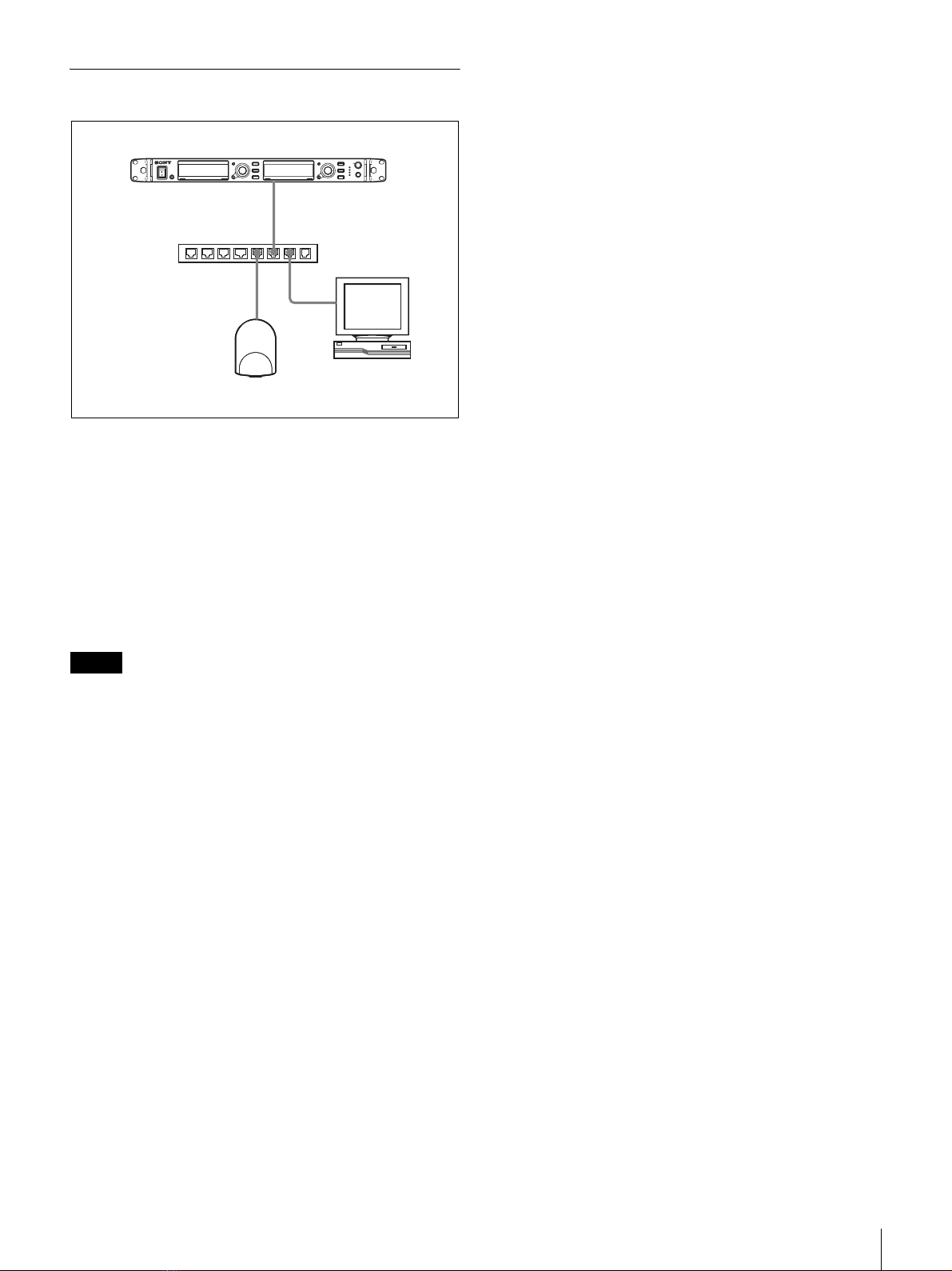
Features
The Wireless Studio software supplied with the
DWR-R01D/DWR-R02D Digital Wireless Receiver
(herein referred to as the “receivers”) allows you monitor
and control a digital wireless system via a network.
The digital wireless system can be accessed from up to six
computers.
Wireless Studio has the following features.
Device monitoring
The software includes a status viewer for monitoring the
operation statuses of the receivers, RMU-01 Remote
Control Units, and transmitters.
The status viewer allows you to monitor a list of
information that is identical to the information that appears
on the initial display of the receiver.
Channel plan selection function
Select a channel plan that is suitable for your signal
environment to ensure stable operations.
Channel Plan Adviser allows you to select a channel plan
while taking into account factors such as other TV
broadcast waves (that you researched beforehand),
frequencies used by other wireless devices in the area, and
frequencies detected via the channel scan.
Error logging function
The software automatically saves log files of problems that
occur during operation. You can review the error histories
at a later time by using a text editor to view the stored log
files.
Device control function
The software allows you to control the receivers and the
transmitters that are paired with the receivers. Control
operations are performed from the Property window and
the Property List tab.
The Property window allows you to control a single
receiver and its paired transmitter while viewing their
operation statuses.
The Property List tab allows you to display the settings of
multiple receivers and transmitters in a list, and perform
fast control operations such as applying the same settings
to all the devices simultaneously.
Recalling stored settings and monitoring
information
Information such as the setting values of devices and the
arrangement of devices in the status viewer can be saved
as a file.
You can recall such information in Wireless Studio at a
later time by loading these stored files.
The setting values recalled in Wireless Studio can be
applied to all the devices.