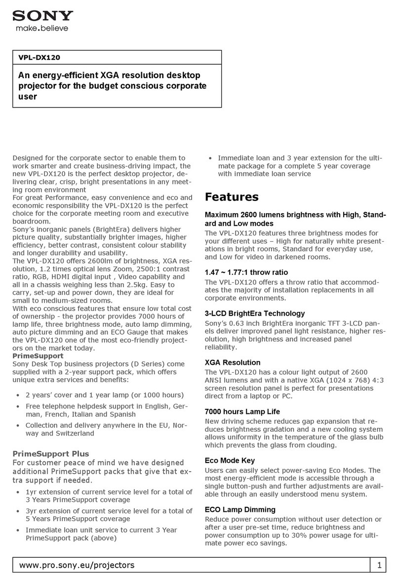
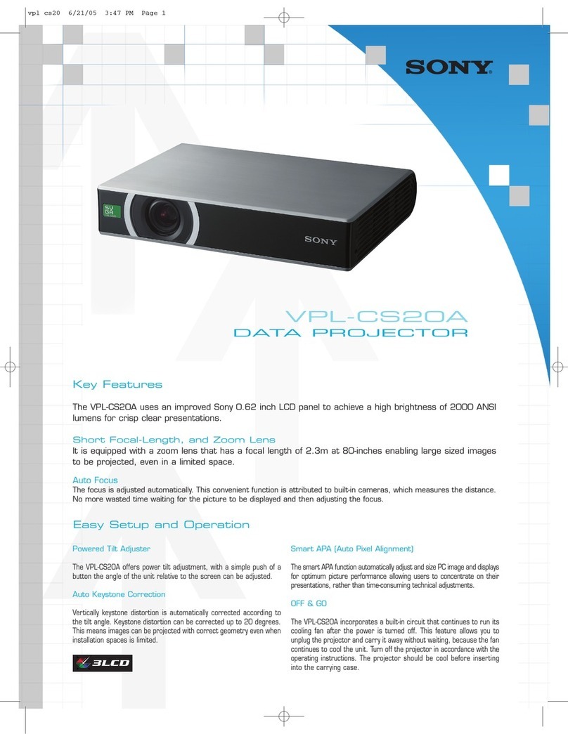
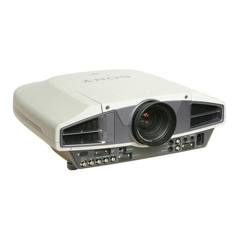
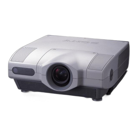
Sony VPL-FX52 User manual

DATA PROJECTOR
VPL-FX52
VPL-FX52L
SERVICE MANUAL
1st Edition (Revised 1)

VPL-FX52/FX52L
!WARNING
This manual is intended for qualified service personnel only.
To reduce the risk of electric shock, fire or injury, do not perform any servicing other than that
contained in the operating instructions unless you are qualified to do so. Refer all servicing to
qualified service personnel.
!WARNUNG
Die Anleitung ist nur für qualifiziertes Fachpersonal bestimmt.
Alle Wartungsarbeiten dürfen nur von qualifiziertem Fachpersonal ausgeführt werden. Um die
Gefahr eines elektrischen Schlages, Feuergefahr und Verletzungen zu vermeiden, sind bei
Wartungsarbeiten strikt die Angaben in der Anleitung zu befolgen. Andere als die angegeben
Wartungsarbeiten dürfen nur von Personen ausgeführt werden, die eine spezielle Befähigung
dazu besitzen.
!AVERTISSEMENT
Ce manual est destiné uniquement aux personnes compétentes en charge de l’entretien. Afin
de réduire les risques de décharge électrique, d’incendie ou de blessure n’effectuer que les
réparations indiquées dans le mode d’emploi à moins d’être qualifié pour en effectuer d’autres.
Pour toute réparation faire appel à une personne compétente uniquement.
For the customers in the U.S.A. and Canada
RECYCLING LITHIUM-ION BATTERIES
Lithium-Ion batteries are recyclable.
You can help preserve our environment
by returning your used rechargeable
batteries to the collection and recycling
location nearest you.
For more information regarding recycling of re-
chargeable batteries, call toll free
1-800-822-8837, or visit http://www.rbrc.org/
Caution: Do not handle damaged or leaking Lithium-Ion
batteries.

VPL-FX52/FX52L 1 (P)
For the customers in the Netherlands
Voor de klanten in Nederland
Hoe u de batterijen moet verwijderen, leest u in de tekst
van deze handleiding.
Gooi de batterij niet weg maar lever deze in als klein
chemisch afval (KCA).
Für Kunden in Deutschland
Entsorgungshinweis: Bitte werfen Sie nur entladene
Batterien in die Sammelboxen beim Handel oder den
Kommunen. Entladen sind Batterien in der Regel dann,
wenn das Gerät abschaltet und signalisiert “Batterie
leer”oder nach längerer Gebrauchsdauer der Batterien
“nicht mehr einwandfrei funktioniert”. Um
sicherzugehen, kleben Sie die Batteriepole z.B. mit
einem Klebestreifen ab oder geben Sie die Batterien
einzeln in einen Plastikbeutel.

VPL-FX52/FX52L
Vorsicht!
Explosionsgefahr bei unsachgemäßem Austausch
der Batterie.
Ersatz nur durch denselben oder einen vom
Hersteller empfohlenen ähnlichen Typ. Entsorgung
gebrauchter Batterien nach Angaben des
Herstellers.
ATTENTION
Il y a danger d’explosion s’il y a remplacement
incorrect de la batterie.
Remplacer uniquement avec une batterie du même
type ou d’un type équivalent recommandépar le
constructeur.
Mettre au rebut les batteries usagées conformément
aux instructions du fabricant.
ADVARSEL!
Lithiumbatteri-Eksplosionsfare ved fejlagtig
håndtering.
Udskiftning måkun ske med batteri
af samme fabrikat og type.
Levér det brugte batteri tilbage til leverandøren.
ADVARSEL
Lithiumbatteri - Eksplosjonsfare.
Ved utskifting benyttes kun batteri som
anbefalt av apparatfabrikanten.
Brukt batteri returneres
apparatleverandøren.
VARNING
Explosionsfara vid felaktigt batteribyte.
Använd samma batterityp eller en likvärdig typ
som rekommenderas av apparattillverkaren.
Kassera använt batteri enligt gällande
föreskrifter.
VAROITUS
Paristo voi räjähtää jos se on virheellisesti
asennettu.
Vaihda paristo ainoastaan laitevalmistajan
suosittelemaan tyyppiin.
Hävitäkäytetty paristo valmistajan ohjeiden
mukaisesti.
CAUTION
Danger of explosion if battery is incorrectly replaced.
Replace only with the same or equivalent type
recommended by the manufacturer.
Dispose of used batteries according to the
manufacturer’s instructions.
2 (P)

1
VPL-FX52/FX52L
Table of Contents
4. Spare Parts
4-1. Notes on Repair Parts ..................................................... 4-1
4-2. Exploded Views .............................................................. 4-2
4-3. Electrical Parts List .......................................................4-13
5. Block Diagrams
Overall (1/2) .............................................................................. 5-1
Overall (2/2) .............................................................................. 5-2
QA ............................................................................................. 5-3
B (1/4), C (1/3), H, NR, QB (1/2) ............................................. 5-4
B (2/4), QB (2/2) ....................................................................... 5-5
B (3/4) ........................................................................................ 5-6
C (2/3) ........................................................................................ 5-7
B (4/4), C (3/3) .......................................................................... 5-8
GA ............................................................................................. 5-9
GB ........................................................................................... 5-10
6. Diagrams
6-1. Frame Schematic Diagrams ............................................6-2
6-2. Schematic Diagrams and Printed Wiring Boards ........... 6-3
Schematic Diagrams
QA (1/4) .......................................................................... 6-4
QA (2/4) .......................................................................... 6-5
QA (3/4) .......................................................................... 6-6
QA (4/4) .......................................................................... 6-7
QB ................................................................................... 6-9
B (1/13) ......................................................................... 6-13
B (2/13) ......................................................................... 6-14
B (3/13) ......................................................................... 6-15
B (4/13) ......................................................................... 6-16
B (5/13) ......................................................................... 6-17
B (6/13) ......................................................................... 6-18
B (7/13) ......................................................................... 6-19
B (8/13) ......................................................................... 6-20
B (9/13) ......................................................................... 6-21
B (10/13) ....................................................................... 6-22
B (11/13) ....................................................................... 6-23
1. Service Information
1-1. Board Layout .................................................................. 1-1
1-2. Disassembly .................................................................... 1-2
1-2-1. Top Cabinet Assy Removal ................................... 1-2
1-2-2. H Board Removal ..................................................1-3
1-2-3. GA Board Removal ............................................... 1-3
1-2-4. GB and S Boards Removal .................................... 1-4
1-2-5. Lamp Fan Duct Assy Removal ............................. 1-4
1-2-6. C Board Removal ..................................................1-5
1-2-7. Prism Block (G) Assy and Out-polarization
Assy Removal ....................................................... 1-5
1-2-8. B Board Removal ..................................................1-6
1-2-9. Lamp Power Supply Removal ............................... 1-7
1-2-10. Lens Assy Removal (VPL-FX52) .........................1-7
1-2-11. Optical Block (G) Assy and S Board Removal .....1-8
1-2-12. DC Fan Removal ................................................... 1-8
1-2-13. Front Panel Assy Removal .................................... 1-9
1-2-14. Connector Block Assy Removal ........................... 1-9
1-2-15. Extension Boards and Extension Cables ............. 1-10
1-2-16. Extension Board Connection ............................... 1-11
1-2-17. Warning on Power Connection ........................... 1-12
2. Electrical Adjustments
2-1. Preparation ...................................................................... 2-1
2-1-1. Required Equipment .............................................. 2-1
2-1-2. How to Enter the Factory Mode ............................ 2-1
2-2. V COM Adjustment ........................................................ 2-1
2-3. Initial Values of Adjustment Items ................................. 2-2
2-4. Service Know-How ........................................................ 2-9
2-4-1. When the Prism Block is Replaced .......................2-9
2-4-2. When the Board is Replaced ................................. 2-9
2-5. White Balance Adjustment ............................................. 2-9
2-5-1. LOW Mode of INPUT-C Computer ..................... 2-9
2-5-2. HIGH Mode of INPUT-C Computer .................. 2-10
2-5-3. LOW Mode of VIDEO ........................................ 2-10
2-5-4. HIGH Mode of VIDEO .......................................2-10
2-6. Memory Structure ......................................................... 2-11
3. Semiconductors
2VPL-FX52/FX52L
B (12/13) ....................................................................... 6-24
B (13/13) ....................................................................... 6-25
C (1/6) ........................................................................... 6-30
C (2/6) ........................................................................... 6-31
C (3/6) ........................................................................... 6-32
C (4/6) ........................................................................... 6-33
C (5/6) ........................................................................... 6-34
C (6/6) ........................................................................... 6-35
H ................................................................................... 6-38
NR ................................................................................. 6-38
S .................................................................................... 6-38
GA (1/3) ........................................................................ 6-39
GA (2/3) ........................................................................ 6-40
GA (3/3) ........................................................................ 6-41
GB (1/2) ........................................................................ 6-45
GB (2/2) ........................................................................ 6-46
Printed Wiring Boards
QA ................................................................................... 6-3
QB ................................................................................... 6-8
B .................................................................................... 6-26
C .................................................................................... 6-28
H ................................................................................... 6-37
NR ................................................................................. 6-37
S .................................................................................... 6-37
GA ................................................................................. 6-42
GB ................................................................................. 6-44

1-1
VPL-FX52/FX52L
Section 1
Service Information
1-1. Board Layout
H
NR
LAMP
POWER
GA
C
B
QA
QB S
GB

1-2 VPL-FX52/FX52L
1Loosen the two screws.
(Special screw M4) 5Top cabinet assy
2Remove the lens cover assy
in the direction of the arrow.
Two claws Three claws
3Screw
(+B 4x10)
4Six screws
(+B 4x10)
CN2200
1-2. Disassembly
1-2-1. Top Cabinet Assy Removal

1-3
VPL-FX52/FX52L
1-2-2. H Board Removal
1Four screws
(+BVTP 4x10)
5Three screws
(+PSW 3x8)
7H board
6Cursor key
4Insulating sheet (H)
2Top cabinet assy
3H holder
CN2201
1-2-3. GA Board Removal
1Two screws
(+PS 4x12)
2Six screws
(+PSW 3x8)
4Remove the GA board
in the direction of the arrow.
3Insulating sheet GA
CN303
CN101
CN105
CN103
GND
GND
CN301
CN202
CN201
CN302

1-4 VPL-FX52/FX52L
3Screw
(+PSW 4x10)
1Five screws
(+PSW 3x8)
2GB board
4S board
CN401
CN501
CN502
CN505
CN504
CN2400
CN402
1-2-4. GB and S Boards Removal
*To remove the GB and S boards, remove the GA board beforehand.
1-2-5. Lamp Fan Duct Assy Removal
Connector (3P)
Connector (3P)
3Loosen the three screws
2DC fan (Sirocco)
4Remove the lamp fan duct assy
in the direction of the arrow.
1Screw
(+PSW 3x8)

1-5
VPL-FX52/FX52L
1-2-6. C Board Removal
1Three screws
(+PSW 3x8) 2C board
CN5601
CN5801
CN5701
CN3010 (board to board)
CN3009 (board to board)
CN5302
CN5307
CN5305
CN5103
CN5306
CN5303
CN5304
1-2-7. Prism Block (G) Assy and Out-polarization Assy Removal
*To remove the prism block (G) assy and Out-polarization assy, remove the C board beforehand.
!/Screw
(+PSW 3x8)
!-Gch in-polarization panel

1-6 VPL-FX52/FX52L
1-2-8. B Board Removal
*To remove the B board, remove the C board beforehand.
1Two screws
(+PSW 4x10) 2Disconnect the two cords.
3Remove the B block assy
in the direction of the arrow A.
6Two screws
(+PSW 3x8)
4Two screws
(+PSW 3x8)
8B board
7B block holder
5B sheet
CN3011
CN3001
A

1-7
VPL-FX52/FX52L
1-2-9. Lamp Power Supply Removal
1Two screws
(+PSW 3x8) 2Four screws
(+PSW 3x8)
3Lamp power supply
CN2
CN1
1-2-10. Lens Assy Removal (VPL-FX52)
Stopper (Chassis side)
Stopper (Lens side)
Stopper (Lens side)
3Remove the lens assy
in the direction of the arrow.
*When replace a Lens Assy,
secure the lens assy to where it
stops at the stopper of chassis.
Three connectors
*Unnecessary when remove lens assy
other than the standard lens assy.
1Two screws
(+B 2x4)
2Two screws
(+PSW 4x12)

1-8 VPL-FX52/FX52L
1-2-12. DC Fan Removal
*To remove the DC fan, remove the C board beforehand.
2Lamp duct (bottom)
1Three
s
crews
(+PSW 4x10) 5DC fan
Connector (3P)
3Lamp duct (top)
4Two
s
crews
(+PSW 3x25)
Four claws
1-2-11. Optical Block (G) Assy and S Board Removal
*To remove the optical block (G) assy and S board, remove the C board beforehand.
CN2400
Connector (4P)
Connector (4P)
3
Five
s
crews
(+PS 4x12)
1
Two
s
crews
(+PWH 3x8)
2
Connector (2P)
5
Screw
(+PSW 4x10)
4
Optical block (G) assy
6
S board
Connector

1-9
VPL-FX52/FX52L
1-2-13. Front Panel Assy Removal
*To remove the front panel assy, remove the C board, lamp duct assy and optical block (G) assy before-
hand.
1Four
s
crews
(+PSW 4x10)
2Two
s
crews
3Remove the front panel assy
in the direction of the arrow.
1-2-14. Connector Block Assy Removal
*To remove the connector block, remove the C board, lamp duct assy, QC board, B block assy, optical
block (G) assy and front panel assy beforehand.
CN2000
CN2101
CN2100
7Five
s
crews
(+PSW 3x8)
4Three
s
crews
(+PSW 3x8)
1Three
s
crews
(+PSW 4x10)
2Remove the connector block assy
in the direction of the arrow.
3Two
s
crews
6Four
s
crews
8QA board
5QB board

1-10 VPL-FX52/FX52L
XF32 board x 3
Flat cable 24P
X702 x 12
Flat cable 32P
XF32 x 3
Cable 2P
XC-C x 1
Cable 3P
XC-C x 1
Cable 4P
XC-C x 1
Cable 7P
XC-C x 1
Cable 11P
XC-C x 1
Cable 50P
XC-C x 1
X702 board x 4XC board x 1
1
2
3
4
5
6
Cable 6P
B-QB x 1 9
Cable 9P
B-QB x 1 0
7
8
X KIT ASSY (A-1159-856-A)
1-2-15. Extension Boards and Extension Cables
n
The numbers of the extension cables and those of the figure correspond each other. (Refer to 1-2-16)

1-11
VPL-FX52/FX52L
B board C board
XC board
NR board
GB
board
CN502
(7P)
H board
XF32 board
QB board
XF702 board
X702 board
X702 board
X702 board
QA board
Lamp power
S board
X702 board
2
2
3
6
7
8
1
1
1
1
1
1
1
9 0
1
11
11
5
4
2
CN1100
(6P) CN2200
(9P)
CN500
(6P)
CN3300
(32P)
CN3400
(32P)
Board to board
(CN5, CN3101)
Board to board
(CN1, CN1103)
Board to board
(CN1, CN1101)
Board to board
(CN6, CN1700)
Board to board
(CN10, CN401)
Board to board
(CN5, CN301)
Board to board
(CN6, CN1102)
Board to board
(CN10, CN3005)
CN3100
(50P)
CN3003
(7P)
CN3500
(32P)
CN501
(9P)
CN3002
(4P)
CN800
(11P)
CN801
(2P)
CN600
(2P)
CN3004
(11P)
CN3001
(3P)
S board
CN600
(2P)
XF32 board
X702 board
XC board
CN11 (32P)
CN12 (32P)
CN10
CN10
CN5,
CN10
CN5,
CN7
CN2,
CN7
CN2,
CN8
CN3,
CN6
CN1,
CN8
CN3,
CN6
CN1,
CN9
CN4,
CN9
CN4,
CN5
CN5000
(2P)
CN5100
(50P)
CN3100
(50P)
CN3000
(2P)
CN3003
(7P)
CN5003
(7P)
CN3002
(4P)
CN3004
(11P)
CN3001
(3P)
CN5002
(4P)
CN5004
(11P)
CN5001
(3P)
CN4
(24P)
CN9
(24P)
CN7
(24P)
CN2
(24P)
CN700
(3P)
CN3000
(2P)
Fix the XC board
with the screw.
XC board
1-2-16. Extension Board Connection
n
The numbers of the extension cables and those of the figure correspond each other. (Refer to 1-2-15)
Be sure to turn on the switch on the S board.

1-12 VPL-FX52/FX52L
1-2-17. Warning on Power Connection
Use a proper power cord for your local power supply.
The United States, Continental UK, Ireland, Japan
Canada Europe Australia, New Zealand
Plug type VM0233 290B YP-12A COX-07 _1) YP332
Female end VM0089 386A YC-13B COX-02 VM0310B YC-13
Cord type SJT SJT H05VV-F H05VV-F N13237/CO-228 VCTF
Rated Voltage & Current 10A/125V 10A/125V 10A/250V 10A/250V 10A/250V 7A/125V
Safety approval UL/CSA UL/CSA VDE VDE VDE DENTORI
Cord length (max.) 4.5m (177 1/4 inches) _

2-1
VPL-FX52/FX52L
Section 2
Electrical Adjustments
2-1. Preparation
2-1-1. Required Equipment
.NTSC, PAL, SECAM component signal generator
LEADER 408-NPS or equivalent
.ASTRO programmable video signal generator
VG-828 or equivalent
.Chroma Meter/Light Meter
Minolta CL-200 or equibalent
n
Allow the warm-up time of 5 minutes after the power is on
before starting the following adjustments.
2-1-2. How to Enter the Factory Mode
1. Confirm that the MENU can be displayed.
2. Close the MENU.
3. Press the keys in the following order : [ENTER] →
[ENTER] → [&] →[ENTER].
The message [Do you want to enter the Factory Mode?
Yes : ↑ No : ↓] appears.
Select [Yes : ↑].
[Supplementary information: How to Exit the
Factory Mode]
Perform the step 3 KEY operation.
The message [Do you want to return to the User Mode?
Yes : ↑ No : ↓] appears.
Select [Yes : ↑].
2-2. V COM Adjustment
1. Input the green-only, 30 IRE single-line ON/OFF
signal to the input connector.
(XGA signal)
2. Enter the G VCOM adjustment screen of the Device
Adjust.
3. Adjust the G VCOM value so that the flicker is
minimal.
4. Switch the input signal from green-only to red-only
(30 IRE) then to blue only (50 IRE) single-line ON/
OFF signal. In the same way as step 3, adjust the R
VCOM and B VCOM values respectively so that the
flicker is minimal.
5. Take note of the adjustment values.
6. Set the “Image Flip” to either V or HV.
7. Input the above R/G/B adjustment values.
8. Take note of the adjustment values.
9. Set the “Image Flip” to OFF.

2-2 VPL-FX52/FX52L
2-3. Initial Values of Adjustment Items
MenuTitle ItemName MemoryName Remark
Set Memory Status Memory Picture Memory W/B Memory
Video / S Video Input A / C Input B Video Computer
Dynamic Standard Dynamic Standard Dynamic Standard High Low High Low
PICTURE SETTING Picture Mode Standard
Adjust Picture...
Contrast 95 80 95 80 95 80
Brightness 50 50 50 50 50 50
Color 50 50 __50 50
Hue 50 50 __50 50
Sharpness 50 50 __50 50
RGB Enhancer __30 30 30 30
Black Level Adj. Off Off __Off Off
Gamma Mode __Graphics Graphics Graphics Graphics
Color Temp. Low Low High High High High
DDE Film Film __Film Film
Volume 30
INPUT SETTING Adjust Signal...
Dot Phase 15 (*)
H Size *
Shift *
Wide Mode Off Off __Off Off
Scan Conv __On On On On
SET SETTING Smart APA On
Auto Input Search Off
Input-C Signal Sel. Computer
Color System Auto
Speaker On
Power Saving Off
IR Reciever Front & Rear
Illumination On
Other manuals for VPL-FX52
6
This manual suits for next models
1
Table of contents
Other Sony Projector manuals

Sony
Sony VPLGH10 User manual

Sony
Sony VPL-CX100 Service manual

Sony
Sony KPR-41EXR95 User manual

Sony
Sony VPL-VW11HT - Lcd Video Projector User manual

Sony
Sony VPH-1041QM User manual

Sony
Sony PL-ES3 User manual

Sony
Sony CPJ-7 Operating Instructions / Manual de instrucciones / Mode... User manual

Sony
Sony VPL-FE110U User manual

Sony
Sony VPL-FX500L User manual

Sony
Sony KP 48S70 User manual