2Table of Contents
Table of Contents
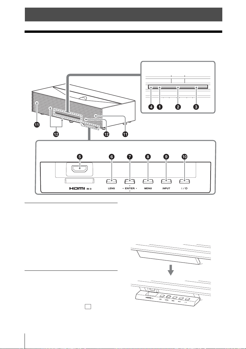
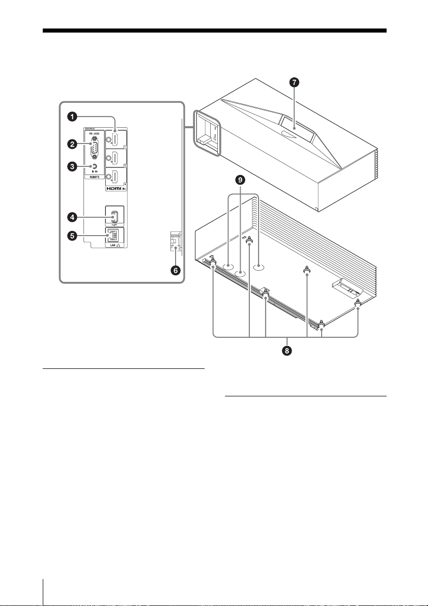
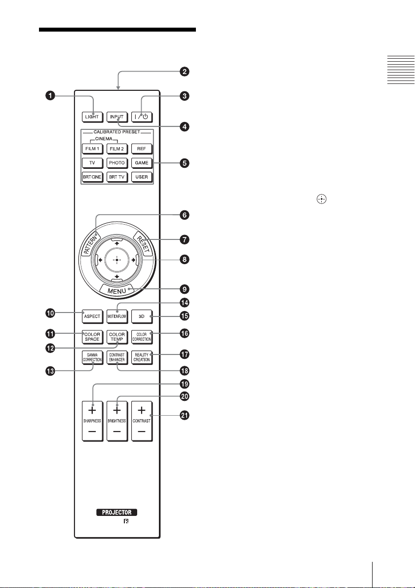
Location of Controls
Front ................................................... 4
Rear/Bottom ....................................... 6
Remote Control .................................. 7
Connections and
Preparations
Installing the Unit .............................. 8
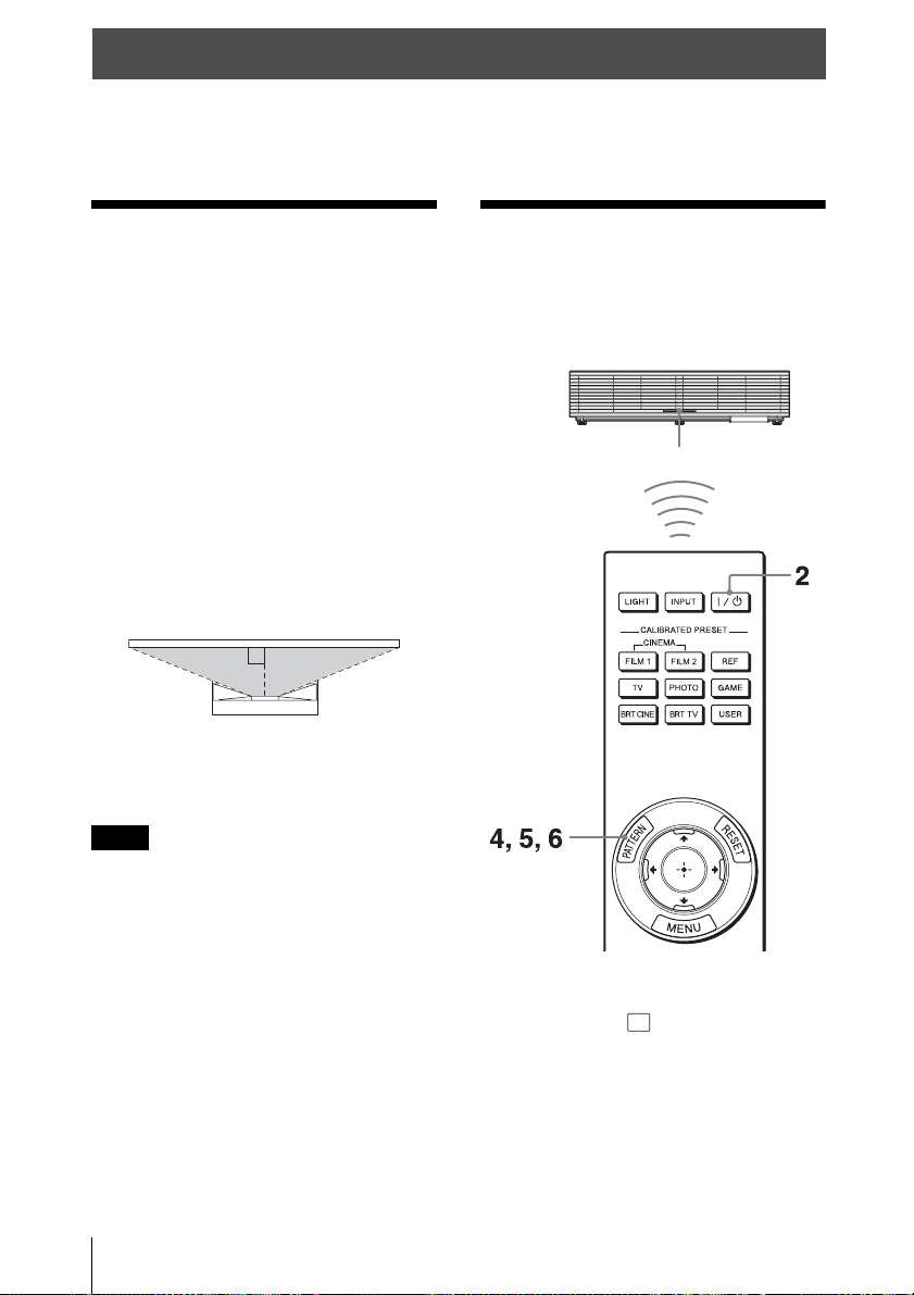
Adjusting the Projection Image .........8
Connecting to Video Equipment or a
Computer ...................................... 14
Projecting
Projecting the Picture ....................... 16
Turning Off the Power ................ 16
Watching 3D Video Images ............. 17
Using the 3D Glasses ................. 17
Using the Picture Position ................ 18
Selecting the Aspect Ratio According to
the Video Signal ........................... 19
Selecting the Picture Viewing
Mode ............................................. 21
Using the Menus
Operation through the Menus .......... 22
Picture Menu .................................... 24
Advanced Picture Menu ................... 29
Screen Menu .................................... 30
Setup Menu ...................................... 32
Function Menu ................................. 34
Installation Menu ............................. 36
Information Menu ............................ 39
About the Preset Memory .......... 39
Using Network Features
Displaying the Control Window of the
Unit with a Web Browser ..............40
Operating the Control Window ........41
Switching the Page ......................41
Setting the Access Limitation .....41
Confirming the Information
Regarding the Unit ..................41
Error Handling
Troubleshooting ................................42
About Indicators ...............................45
Message Lists ...................................46
Others
Updating the Software ......................47
About x.v.Color ................................47
About the Simulated 3D Feature ......48
Cleaning ............................................48
Specifications ...................................49
Preset Signals ..............................50
Input Signals and Adjustment/
Setting Items ............................52
Compatible 3D Signals ...............53
3D Signals and Adjustment/Setting
Items ........................................53
Aspect Mode ...............................55
Storage Conditions of Adjustment/
Setting Items ............................55
Installation Distance and Projection
Image Size .....................................57
Dimensions .......................................60
NOTICES AND LICENCES
FOR SOFTWARE USED IN THIS
PRODUCT ....................................63