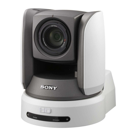
Using the BRC-H700/BRC-Z700 as a Second Camera for the PCS-HG90 Video Conferencing System 3
What is the BRC Series?.............................................4
Product Lineup....................................................................7
Key Features..........................................................................8
System Configuration ...............................................10
4.1 BRC-H700 Simple System ........................................12
4.2 BRC-H700/BRU-H700 System.................................12
4.3 BRC-Z700 Simple System .........................................13
4.4 BRC-Z700/BRU-H700 System..................................13
4.5 BRC-300/300P Simple System..............................13
4.6 BRC-300/300P and BRU-300/300P System ....14
4.7 Daisy-chain System.....................................................14
Location and Function of Parts ......................15
5.1 The BRC Series of Cameras...................................15
5.1.1 BRC-H700.................................................................15
5.1.2 BRC-Z700 .................................................................16
5.1.3 BRC-300/300P ......................................................18
5.2 Optical Multiplex Units .............................................19
5.2.1
BRU-H700 HD Optical Multiplex Unit for use
with the BRC-H700 and BRC-Z700
...................19
5.2.2
BRU-300/300P SD Optical Multiplex Unit for
use with the BRC-300/300P
...............................20
5.3 Optical Multiplex Cards and Optional Video
Cards ...................................................................................20
5.3.1
BRBK-H700 HD Optical Multiplex Card
...........20
5.3.2
HFBK-HD1 HD Interface Board
...........................21
5.3.3
HFBK-SD1 SD Interface Board
............................21
5.3.4
HFBK-XG1 XGA Interface Board
........................21
5.3.5
HFBK-TS1 HDV Interface Board
..........................21
5.3.6
BRBK-MF1 HD Optical Multiplex Card
............22
5.3.7
BRBK-HSD1 HD/SD-SDI Output Card
...............22
5.3.8
BRBK-303 SD Optical Multiplex Card
..............22
5.3.9
BRBK-301 Analog RGB Component Card
.......22
5.3.10
BRBK-302 SDI Card
..............................................22
5.3.11
BRBK-304 i.LINK DV Card
...................................22
Table of contents
1
2
3
4
5
Basic Set-up and Operation..............................23
6.1 Connections ...................................................................23
6.2 Monitor Set-up................................................................23
Remote Operation .......................................................24
7.1 IR Remote Commander Unit.................................24
7.2 RM-BR300 Remote Control Unit...........................25
7.2.1 Features ...................................................................25
7.2.2 Operation ...............................................................26
Operation with the AWS-G500/G500HD
Anycast Station...............................................................33
8.1 Controlling camera with the
AWS-G500/G500HD Any cast station............33
8.2
Controlling the camera with VISCA support
......34
8.3 Operating the PGM and NEXT Selection
buttons from the RM-BR300..................................35
Using the BRC-H700/BRC-Z700 as a Second
Camera for the PCS-XG80 Video
Conferencing System
..................................................36
Specifications...................................................................37
Dimensions ..........................................................................39
Technical Appendix...................................................43
12.1 Color Adjustment......................................................43
12.2 Color Detail ...................................................................43
12.3 Estimated Viewing Angle of BRC Sereis......44
12.4 Sync Lock Setting......................................................48
12.5 Recommended Lighting Conditions............48
12.6
Using the VISCA RS-422 Connector Plug
..........48
12.7 Wiring Diagram of VISCA RS-422
Connection...................................................................49
12.8 CCFC Cable Information.....................................50
Installing the Camera in a High Position
.....51
7
8
9
10
11
12
6
13
