Sony BKPF-L753A User manual

ANALOG AUDIO DISTRIBUTION BOARD
BKPF-L753A
MAINTENANCE MANUAL
1st Edition (Revised 1)
Serial No. 10001 and Higher

!WARNING
This manual is intended for qualified service personnel only.
To reduce the risk of electric shock, fire or injury, do not perform any servicing other than that
contained in the operating instructions unless you are qualified to do so. Refer all servicing to
qualified service personnel.
!WARNUNG
Die Anleitung ist nur für qualifiziertes Fachpersonal bestimmt.
Alle Wartungsarbeiten dürfen nur von qualifiziertem Fachpersonal ausgeführt werden. Um die
Gefahr eines elektrischen Schlages, Feuergefahr und Verletzungen zu vermeiden, sind bei
Wartungsarbeiten strikt die Angaben in der Anleitung zu befolgen.Andere als die angegeben
Wartungsarbeiten dürfen nur von Personen ausgeführt werden, die eine spezielle Befähigung
dazu besitzen.
!AVERTISSEMENT
Ce manual est destiné uniquement aux personnes compétentes en charge de l’entretien.Afin
de réduire les risques de décharge électrique, d’incendie ou de blessure n’effectuer que les
réparations indiquées dans le mode d’emploi à moins d’être qualifié pour en effectuer d’autres.
Pour toute réparation faire appel à une personne compétente uniquement.
BKPF-L753A

1 (E)
BKPF-L753A
Table of Contents
Manual Structure
Purpose of this manual ........................................................................................ 3 (E)
Contents ............................................................................................................... 3 (E)
Related manuals................................................................................................... 3 (E)
1. Service Overview
1-1. Notes on Repair Parts............................................................................1-1 (E)
1-2. IC Link Replacement ............................................................................1-1 (E)
1-3. Shield Case (S/N10001 through S/N17325) .........................................1-1 (E)
1-4. Name and Function of Switch/Indicator/etc. ........................................1-2 (E)
1-5. Unleaded Solder ....................................................................................1-3 (E)
2. Electrical Alignment
2-1. Electrical Alignment Overview.............................................................2-1 (E)
2-1-1. Required Equipment and Tools............................................2-1 (E)
2-1-2. Connection ...........................................................................2-1 (E)
2-2. Preparation of Adjustment ....................................................................2-2 (E)
2-3. Input/Output Gain Adjustment..............................................................2-2 (E)
2-4. CMRR (Common Mode Rejection Ratio) Adjustment.........................2-3 (E)
2-5. Input/Output Gain Adjustment for Customer Setting ...........................2-3 (E)
3. Spare Parts
ADA-55 ..................................................................................................................3-1
CN-1855/1856 ........................................................................................................3-4
DD-36 .....................................................................................................................3-4
4. Semiconductor Pin Assignments
5. Block Diagram
Overall ....................................................................................................................5-1

2 (E) BKPF-L753A
6. Schematic Diagrams
ADA-55 ..................................................................................................................6-2
CN-1855/1856 ........................................................................................................6-3
DD-36 .....................................................................................................................6-4
7. Board Layouts
ADA-55 ..................................................................................................................7-1
DD-36 .....................................................................................................................7-2

3 (E)
BKPF-L753A
Purpose of this manual This manual is the maintenance manual of Analog Audio Distribution Board
BKPF-L753A.
This manual is intended for use by trained system and service engineers, and
describes the information for periodic maintenance and detailed service.
Contents This manual is organized by following sections.
Section 1 Service Overview
This section explains the notes on repair parts and IC link replacement.
Section 2 Electrical Alignment
This section explains the adjustment after replacing part.
Section 3 Spare Parts
This section describes the spare parts.
Section 4 Semiconductor Pin Assignments
This section describes the pin assignments of semiconductor.
Section 5 Block Diagram
This section describes the overall block diagram.
Section 6 Schematic Diagrams
This section describes the schematic diagrams of the ADA-55, DD-36 and
CN-1855/1856 boards.
Section 7 Board Layouts
This section describes the board layouts for the ADA-55 and DD-36 boards.
Related manuals The following manual is prepared for this unit.
..
..
.Installation Manual (Supplied with BKPF-L753A)
This manual describes the information on BKPF-L753A installing.
Manual Structure


1-1 (E)
BKPF-L753A
Section 1
Service Overview
1-2. IC Link Replacement
w
An IC link is critical parts to safe operation.
Replace this component with Sony parts whose part
numbers appear in this manual published by Sony.
If not, this may cause a fire or electric shock.
Be sure to use the specified component in this manual.
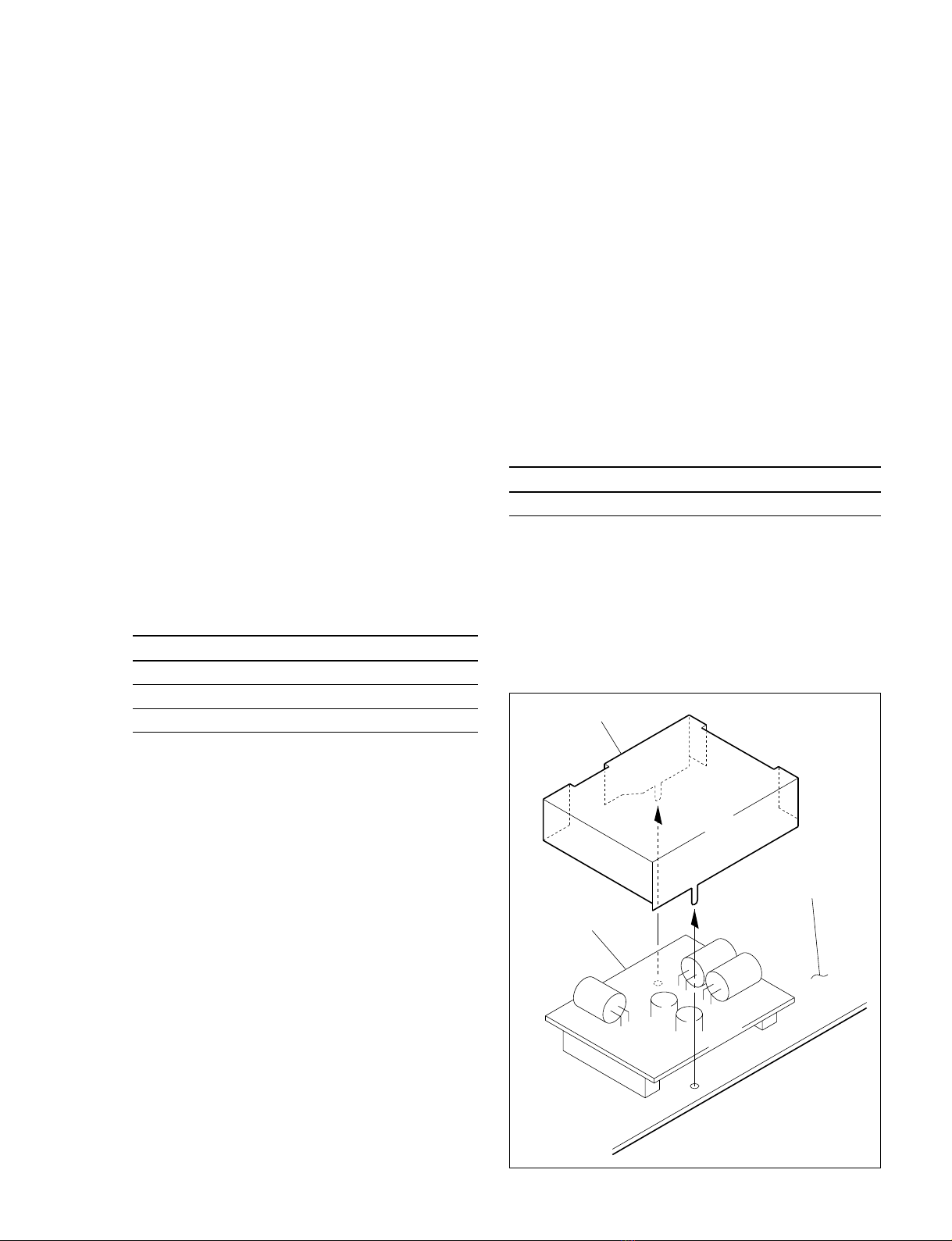
The IC link is mounted on the ADA-55 board. Be sure to
replace with the specified IC link as shown below after
removing the foreign substances that may cause the shorts.
ADA-55 Board
Ref No. (Address) Description Part No.
PS1 (K-3) IC link 2 A !1-533-282-21
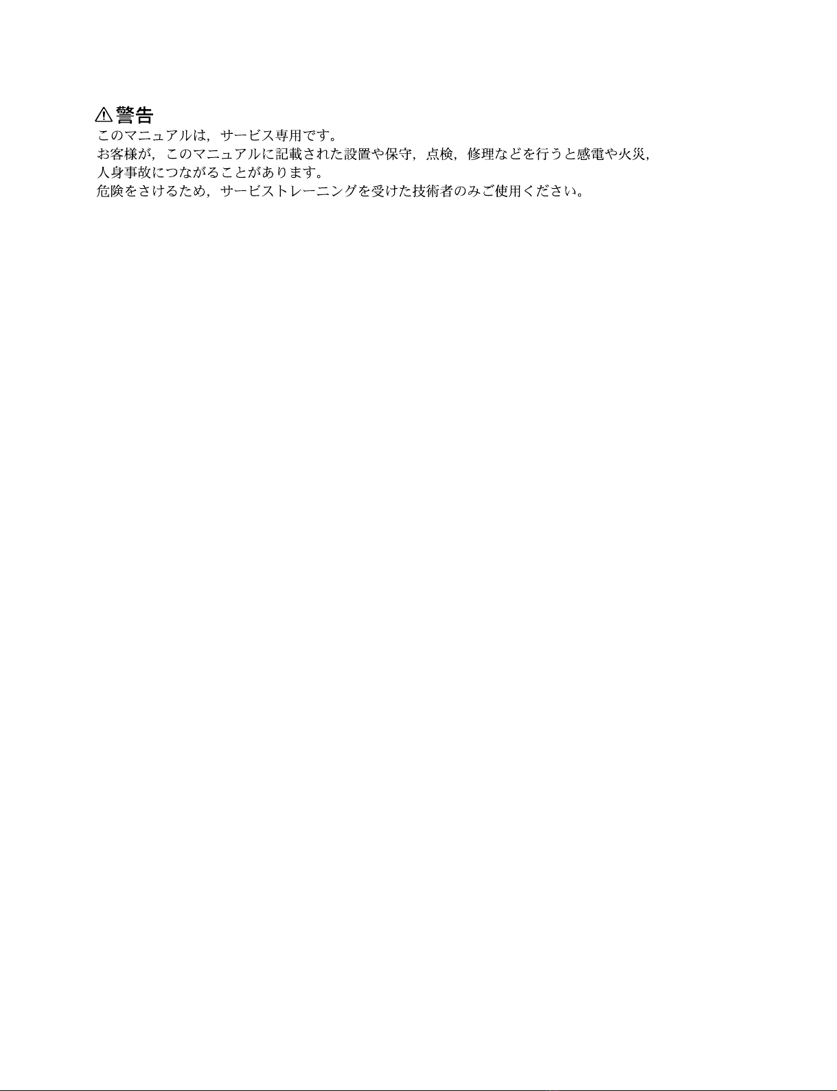
1-3. Shield Case
(S/N10001 through S/N17325)
The shield case is a component to shield the DD-36 board.
Before checking the DD-36 board, unsolder and remove
this shield case.
1-1. Notes on Repair Parts
1. Safety Related Components Warning
w
Components marked !are critical to safe operation.
Therefore, specified parts should be used in the case of
replacement.
2. Standardization of Parts
Some repair parts supplied by Sony differ from those
used for the unit. These are because of parts common-
ality and improvement.
Parts list has the present standardized repair parts.
3. Stock of Parts
Parts marked with “o” at SP (Supply code) column of
the spare parts list may not be stocked. Therefore, the
delivery date will be delayed.
4. Units Representation
The following represented units are changed or
omitted in writing.
Units Representation
Capacitance uFuF
Inductance uHuH
Resistance ZAbbreviation
n
For the replacement of the ADA-55 board, please buy
BKPF-L753A because ADA-55 mounted circuit board is
not prepared for spare parts.
Shield case
DD-36 board
ADA-55 board

1-2 (E) BKPF-L753A
1-4. Name and Function of Switch/Indicator/etc.
Main Board (ADA-55 Board: Side A)
Switches/shorting plugs (Factory default settings are indicated by a \\
\\
\mark)
No. Ref. No. Name Function
7S1 AUDIO 1 600 ZSelects the input impedance of the signal input to the AUDIO 1 connector.
OFF: 20 kZ
\ON: 600 Z
8S2 AUDIO 2 600 ZSelects the input impedance of the signal input to the AUDIO 2 connector.
OFF: 20 kZ
\ON: 600 Z
4COR1 AUDIO 2 GAIN Selects an input/output gain of the signal input to the AUDIO 2 connector.
(Valid only when COR3 is set to ST.)
+8 dB +4 dB \0 dB _4 dB _8 dB
1COR2 AUDIO 1 GAIN Selects an input/output gain of the signal input to the AUDIO 1 connector.
+8 dB +4 dB \0 dB _4 dB _8 dB
6COR3 MONAURAL/STEREO Selects monaural or stereo mode of the analog audio signal input/output.
MO (Monaural): The signal input to the AUDIO 1 connector is distributed to eight outputs
\ST (Stereo): The each signal input to the AUDIO 1 and AUDIO 2 connectors is distributed to
four outputs
Indicator
No. Ref. No. Name Color Function
3D1 POWER Green/red Green: A power supply of ±12 V is normal
Red: A power supply of ±12 V is abnormal
Gain adjusting VR
No. Ref. No. Name Function
5RV3 AUDIO 2 FINE VR Adjusts the gain of the signal input to AUDIO 2 connector within the ±2 dB range.
2RV4 AUDIO 1 FINE VR Adjusts the gain of the signal input to AUDIO 1 connector within the ±2 dB range.
n
At the factory-out, the gain adjusting VRs were adjusted to 0 dB. (the standard level +4 dBm)
3
4
5
S1
S2
6
2
7 8
1
COR2
COR1
MO
RV4
RV3
D1 COR3
ST
+8
+4
0
_4
_8
+8
+4
0
_4
_8
1-4. Name and Function of Switch/Indicator/etc.

1-3 (E)
BKPF-L753A
1-5. Unleaded Solder
Boards requiring use of unleaded solder are printed with a
lead free mark (LF) indicating the solder contains no lead.
(Caution: Some printed circuit boards may not come
printed with the lead free mark due to their particular size.)
: LEAD FREE MARK
m
.Be sure to use the unleaded solder for the printed circuit
board printed with the lead free mark.
.The unleaded solder melts at a temperature about 40 dC
higher than the ordinary solder, therefore, it is recom-
mended to use the soldering iron having a temperature
regulator.
.The ordinary soldering iron can be used but the iron tip
has to be applied to the solder joint for a slightly longer
time. The printed pattern (copper foil) may peel away if
the heated tip is applied for too long, so be careful.
1-5. Unleaded Solder


2-1 (E)
BKPF-L753A
Section 2
Electrical Alignment
2-1. Electrical Alignment Overview
2-1-1. Required Equipment and Tools
Use the equipment listed below or the equivalent.
Item Model Remarks
Extension board EX-731 (Part No. A-8322-598-A)
Audio signal generator *Tektronix SG505 (Option-02)
Audio level meter *—
Interface unit Sony PFV-L1 or PFV-L10
Adjustment screwdriver — Insulation type
Resister (600 Z , within 1 %) with lead
*: Use the equipment after calibration has been completed.
2-1-2. Connection
PFV-L1/L10 (Rear)PFV-L1/L10 (Side)
Extension board EX-731
Audio level mater
Analog audio signal generator
ADA-55 board
600 Z
+
_
INPUT
BKPF-L753A
OUT
AUDIO AUDIO
12
+
IN
_
G
+
_
G
+
+
_
G
_
G
+
_
G
+
_
G
+
+
_
G
_
G
+
_
G
2
3
4
+
IN
_
G
1
2
3
4
1
L753A
OUTPUTOUTPUT
(At CMMR adj.) (At Gain adj.)
+
COMCOM _
+
_

2-2 (E) BKPF-L753A
2-2. Preparation of Adjustment
2-3. Input/Output Gain Adjustment
Measuring equipment: Audio level meter
1. Set the output of the generator to +4.0 dBm, 1 kHz.
(0 dBm =0.775 Vrms)
CH1 adjustment
2. Connect the audio signal generator to the input of CH1
connector.
3. Connect the audio level meter to one output of CH1
connector.
4. Check that COR2 (A-1) is set to 0 dB.
If not, set it to 0 dB.
5. Adjust the CH1 output level on the audio level meter.
Adjustment point: 1RV4/ADA-55 (A-2)
Specification: 4.0 ±0.1 dBm (at 600 Zload)
CH2 adjustment
6. Connect the audio signal generator to the input of CH2
connector.
7. Connect the audio level meter to one output of CH2
connector.
8. Check that COR1 (A-3) is set to 0 dB.
If not, set it to 0 dB.
9. Adjust the CH2 output level on the audio level meter.
Adjustment point: 1RV3/ADA-55 (A-3)
Specification: 4.0 ±0.1 dBm (at 600 Zload)
S1
S2
COR2
COR1
MO
RV4
RV3
D1
RV1
RV2
COR3
ST
+8
+4
0
_4
_8
+8
+4
0
_4
_8
1
1
ADA-55 Board (Side A)
2-2. Preparation of Adjustment
1. Extend the ADA-55 board with a extension board.
2. Write the customer settings of the shorting plugs
(COR1, COR2, and COR3) and switches (S1, and S2)
on the ADA-55 board down in following table.
3. Set their shorting plugs and switches as follows:
Ref. No. (Address) Setting at adj. Customer setting
COR1 (A-3) 0 dB
COR2 (A-1) 0 dB
COR3 (C-2) ST (STEREO)
S1 (D-1) ON (600 Z)
S2 (D-2) ON (600 Z)
4. Turn on the power of equipment (the signal generator,
audio level meter, and interface unit PFV-L1 or
PFV-L10), and warm up them for about ten minutes.
5. Attach the 600 Zresister for termination to the audio
level meter.

2-3 (E)
BKPF-L753A
2-4. CMRR (Common Mode Rejection
Ratio) Adjustment
Measuring equipment: Audio level meter
1. Set the output of the generator to +15.0 dBm, 60 Hz.
CH2 adjustment
2. Connect the audio signal generator to the input of CH2
connector.
3. Connect the audio level meter to one output of CH2
connector.
4. Adjust the CH2 output level on the audio level meter.
Adjustment point: 1RV2/ADA-55 (C-2)
Specification: Less than _65 dBm (at 600 Zload)
CH1 adjustment
5. Connect the audio signal generator to the input of CH1
connector.
6. Connect the audio level meter to one output of CH1
connector.
7. Adjust the CH1 output level on the audio level meter.
Adjustment point: 1RV1/ADA-55 (C-1)
Specification: Less than _65 dBm (at 600 Zload)
2-5. Input/Output Gain Adjustment for
Customer Setting
n
When the audio gain (COR1 or COR2) is not 0 dB, be sure
to perform this adjustment.
Measuring equipment: Audio level meter
1. Reset the shorting plugs (COR1 and COR2) on the
ADA-55 board to customer settings.
CH1 adjustment
2. Set the output of the generator to the customer setting
of COR1 as follows:
COR1/COR2 customer setting Output signal
_8 dB +12.0 dBm, 1 kHz
_4 dB +8.0 dBm, 1 kHz
(0 dB) (+4.0 dBm, 1 kHz)
+4 dB 0.0 dBm, 1 kHz
+8 dB _4.0 dBm, 1 kHz
(0 dBm =0.775 Vrms)
3. Connect the audio signal generator to the input of CH1
connector.
4. Connect the audio level meter to one output of CH1
connector.
5. Adjust the CH1 output level on the audio level meter.
Adjustment point: 1RV4/ADA-55 (A-2)
Specification: 4.0 ±0.1 dBm (at 600 Zload)
CH2 adjustment
6. Set the output of the generator to the customer setting
of COR2. (Refer to table in step 2.)
7. Connect the audio signal generator to the input of CH2
connector.
8. Connect the audio level meter to one output of CH2
connector.
9. Adjust the CH2 output level on the audio level meter.
Adjustment point: 1RV3/ADA-55 (A-3)
Specification: 4.0 ±0.1 dBm (at 600 Zload)
10. After turning off the power, reset the shorting plug
(COR3) and switches (S1 and S2) on the ADA-55
board to the customer settings.
2-4. CMRR (Common Mode Rejection Ratio) Adjustment
2-5. Input/Output Gain Adjustment for Customer Setting


3-1
BKPF-L753A
Section 3
Spare Parts
------------
ADA-55 BOARD
------------
*1:[Board No. suffix -11,12]
*2:[Board No. suffix -14]
Ref. No.
or Q'ty Part No. SP Description
1pc 3-179-084-01 s LEVER (R), PC BOARD
or 3-179-085-01 s LEVER (L), PC BOARD
1pc 3-194-617-01 o HEAT SINK
1pc 3-203-115-01 o CASE, SHIELD (for DD1)
2pcs 7-685-547-14 s SCREW +BTP 3x10
8pcs 7-682-948-01 s SCREW +PSW 3x8
C1 1-164-346-11 s CERAMIC, CHIP 1.0uF 16V (2012)
C2 1-126-391-11 s ELECT, CHIP 47uF 20% 6.3V
C3 1-164-346-11 s CERAMIC, CHIP 1.0uF 16V (2012)
C4 1-126-396-11 s ELECT, CHIP 47uF 20% 16V
C5 1-126-396-11 s ELECT, CHIP 47uF 20% 16V
C6 1-126-396-11 s ELECT, CHIP 47uF 20% 16V
C7 1-126-396-11 s ELECT, CHIP 47uF 20% 16V
C8 1-163-113-00 s CERAMIC, CHIP 68pF 5% 50V (2012)
C9 1-126-396-11 s ELECT, CHIP 47uF 20% 16V
C10 1-126-396-11 s ELECT, CHIP 47uF 20% 16V
C11 1-163-113-00 s CERAMIC, CHIP 68pF 5% 50V (2012)
C12 1-164-346-11 s CERAMIC, CHIP 1.0uF 16V (2012)
C13 1-164-346-11 s CERAMIC, CHIP 1.0uF 16V (2012)
C14 1-164-346-11 s CERAMIC, CHIP 1.0uF 16V (2012)
C15 1-164-346-11 s CERAMIC, CHIP 1.0uF 16V (2012)
C16 *2 1-117-681-11 s CAPACITOR, ELECT 100MF/16V
*1 1-128-397-21 s ELECT 100uF 20% 16V
C17 *2 1-117-681-11 s CAPACITOR, ELECT 100MF/16V
*1 1-128-397-21 s ELECT 100uF 20% 16V
C18 *2 1-117-681-11 s CAPACITOR, ELECT 100MF/16V
*1 1-128-397-21 s ELECT 100uF 20% 16V
C19 *2 1-117-681-11 s CAPACITOR, ELECT 100MF/16V
*1 1-128-397-21 s ELECT 100uF 20% 16V
C20 1-164-346-11 s CERAMIC, CHIP 1.0uF 16V (2012)
C21 1-164-346-11 s CERAMIC, CHIP 1.0uF 16V (2012)
C22 1-164-346-11 s CERAMIC, CHIP 1.0uF 16V (2012)
C23 1-164-346-11 s CERAMIC, CHIP 1.0uF 16V (2012)
C24 1-163-224-11 s CERAMIC, CHIP 7pF 50V (2012)
C25 1-164-346-11 s CERAMIC, CHIP 1.0uF 16V (2012)
C26 1-164-346-11 s CERAMIC, CHIP 1.0uF 16V (2012)
C27 1-126-396-11 s ELECT, CHIP 47uF 20% 16V
C28 1-126-396-11 s ELECT, CHIP 47uF 20% 16V
C29 1-163-235-11 s CERAMIC, CHIP 22pF 5% 50V (2012)
C30 1-126-396-11 s ELECT, CHIP 47uF 20% 16V
C31 1-126-396-11 s ELECT, CHIP 47uF 20% 16V
C32 1-164-346-11 s CERAMIC, CHIP 1.0uF 16V (2012)
C33 1-164-346-11 s CERAMIC, CHIP 1.0uF 16V (2012)
C34 1-126-396-11 s ELECT, CHIP 47uF 20% 16V
C35 1-126-396-11 s ELECT, CHIP 47uF 20% 16V
C36 1-163-224-11 s CERAMIC, CHIP 7pF 50V (2012)
C37 1-164-346-11 s CERAMIC, CHIP 1.0uF 16V (2012)
C38 1-164-346-11 s CERAMIC, CHIP 1.0uF 16V (2012)
C39 1-126-396-11 s ELECT, CHIP 47uF 20% 16V
C40 1-126-396-11 s ELECT, CHIP 47uF 20% 16V
C41 1-163-235-11 s CERAMIC, CHIP 22pF 5% 50V (2012)
C42 1-107-781-11 s ELECT, NONPOLAR 47uF 20% 16V
C43 1-107-781-11 s ELECT, NONPOLAR 47uF 20% 16V
(ADA-55 BOARD)
Ref. No.
or Q'ty Part No. SP Description
C44 1-107-781-11 s ELECT, NONPOLAR 47uF 20% 16V
C45 1-107-781-11 s ELECT, NONPOLAR 47uF 20% 16V
C46 1-163-227-11 s CERAMIC, CHIP 10pF 5% 50V (2012)
C47 1-163-224-11 s CERAMIC, CHIP 7pF 50V (2012)
C48 1-164-346-11 s CERAMIC, CHIP 1.0uF 16V (2012)
C49 1-164-346-11 s CERAMIC, CHIP 1.0uF 16V (2012)
C50 1-163-227-11 s CERAMIC, CHIP 10pF 5% 50V (2012)
C51 1-163-224-11 s CERAMIC, CHIP 7pF 50V (2012)
C52 1-164-346-11 s CERAMIC, CHIP 1.0uF 16V (2012)
C53 1-164-346-11 s CERAMIC, CHIP 1.0uF 16V (2012)
C54 1-163-227-11 s CERAMIC, CHIP 10pF 5% 50V (2012)
C55 1-163-224-11 s CERAMIC, CHIP 7pF 50V (2012)
C56 1-164-346-11 s CERAMIC, CHIP 1.0uF 16V (2012)
C57 1-164-346-11 s CERAMIC, CHIP 1.0uF 16V (2012)
C58 1-163-227-11 s CERAMIC, CHIP 10pF 5% 50V (2012)
C59 1-163-224-11 s CERAMIC, CHIP 7pF 50V (2012)
C60 1-164-346-11 s CERAMIC, CHIP 1.0uF 16V (2012)
C61 1-164-346-11 s CERAMIC, CHIP 1.0uF 16V (2012)
C62 1-126-396-11 s ELECT, CHIP 47uF 20% 16V
C63 1-126-396-11 s ELECT, CHIP 47uF 20% 16V
C64 1-126-396-11 s ELECT, CHIP 47uF 20% 16V
C65 1-126-396-11 s ELECT, CHIP 47uF 20% 16V
C66 1-126-396-11 s ELECT, CHIP 47uF 20% 16V
C67 1-126-396-11 s ELECT, CHIP 47uF 20% 16V
C68 1-126-396-11 s ELECT, CHIP 47uF 20% 16V
C69 1-126-396-11 s ELECT, CHIP 47uF 20% 16V
C70 1-163-235-11 s CERAMIC, CHIP 22pF 5% 50V (2012)
C71 1-163-235-11 s CERAMIC, CHIP 22pF 5% 50V (2012)
C72 1-163-235-11 s CERAMIC, CHIP 22pF 5% 50V (2012)
C73 1-163-235-11 s CERAMIC, CHIP 22pF 5% 50V (2012)
C74 1-107-420-11 s ELECT, CHIP 47uF 20% 35V
C75 1-107-420-11 s ELECT, CHIP 47uF 20% 35V
C76 1-107-420-11 s ELECT, CHIP 47uF 20% 35V
C77 1-107-420-11 s ELECT, CHIP 47uF 20% 35V
C78 1-163-241-11 s CERAMIC, CHIP 39pF 5% 50V (2012)
C79 1-163-241-11 s CERAMIC, CHIP 39pF 5% 50V (2012)
C80 1-163-241-11 s CERAMIC, CHIP 39pF 5% 50V (2012)
C81 1-163-241-11 s CERAMIC, CHIP 39pF 5% 50V (2012)
C82 1-163-241-11 s CERAMIC, CHIP 39pF 5% 50V (2012)
C83 1-163-241-11 s CERAMIC, CHIP 39pF 5% 50V (2012)
C84 1-163-241-11 s CERAMIC, CHIP 39pF 5% 50V (2012)
C85 1-163-241-11 s CERAMIC, CHIP 39pF 5% 50V (2012)
C86 *2 1-117-681-11 s CAPACITOR, ELECT 100MF/16V
*1 1-128-397-21 s ELECT 100uF 20% 16V
C87 *2 1-117-681-11 s CAPACITOR, ELECT 100MF/16V
*1 1-128-397-21 s ELECT 100uF 20% 16V
C88 *2 1-117-681-11 s CAPACITOR, ELECT 100MF/16V
*1 1-128-397-21 s ELECT 100uF 20% 16V
C89 *2 1-117-681-11 s CAPACITOR, ELECT 100MF/16V
*1 1-128-397-21 s ELECT 100uF 20% 16V
C90 1-164-346-11 s CERAMIC, CHIP 1.0uF 16V (2012)
C91 1-164-346-11 s CERAMIC, CHIP 1.0uF 16V (2012)
C92 1-164-346-11 s CERAMIC, CHIP 1.0uF 16V (2012)
C93 1-164-346-11 s CERAMIC, CHIP 1.0uF 16V (2012)
C94 1-164-346-11 s CERAMIC, CHIP 1.0uF 16V (2012)
C95 1-164-346-11 s CERAMIC, CHIP 1.0uF 16V (2012)
C96 1-164-346-11 s CERAMIC, CHIP 1.0uF 16V (2012)

3-2 BKPF-L753A
(ADA-55 BOARD)
Ref. No.
or Q'ty Part No. SP Description
C97 1-164-346-11 s CERAMIC, CHIP 1.0uF 16V (2012)
C98 1-164-346-11 s CERAMIC, CHIP 1.0uF 16V (2012)
(S/N 10001 to 11870)
CN101 1-506-746-11 s CONNECTOR, DIN 48P, MALE
COP1 1-562-579-11 s PLUG, SHORTING
COP2 1-562-579-11 s PLUG, SHORTING
COP3 1-562-579-11 s PLUG, SHORTING
COR1 1-691-506-11 s CONNECTOR, 10P, MALE
COR2 1-691-506-11 s CONNECTOR, 10P, MALE
COR3 1-564-948-11 o CONNECTOR, 3P, MALE
D1 8-719-027-84 s LED CL-155UR/G-D, RED/GRN
DD36 *2 1-475-611-11 s CONVERTER UNIT, DC-DC
IC1 8-759-700-96 s IC NJM5534M
IC2 8-759-700-96 s IC NJM5534M
IC3 8-759-700-96 s IC NJM5534M
IC4 8-759-700-96 s IC NJM5534M
IC5 8-759-700-96 s IC NJM5534M
IC6 8-759-700-96 s IC NJM5534M
IC7 8-759-700-96 s IC NJM5534M
IC8 8-759-700-96 s IC NJM5534M
IC9 8-759-700-96 s IC NJM5534M
IC10 8-759-700-96 s IC NJM5534M
IC11 8-759-990-63 s IC PCF8574AT
(S/N 10001 to 11870)
L1 1-424-643-11 s COIL, CHOKE 10uH
L2 1-424-643-11 s COIL, CHOKE 10uH
L3 1-424-643-11 s COIL, CHOKE 10uH
PS1 !1-533-282-21 s LINK, IC, CHIP 2A
Q1 8-729-120-28 s TRANSISTOR 2SC1623-L5L6
Q2 8-729-120-28 s TRANSISTOR 2SC1623-L5L6
Q3 8-729-216-22 s TRANSISTOR 2SA1162-G
Q4 8-729-120-28 s TRANSISTOR 2SC1623-L5L6
Q5 8-729-120-28 s TRANSISTOR 2SC1623-L5L6
Q6 8-729-216-22 s TRANSISTOR 2SA1162-G
Q7 8-729-120-28 s TRANSISTOR 2SC1623-L5L6
Q8 8-729-216-22 s TRANSISTOR 2SA1162-G
Q9 8-729-120-28 s TRANSISTOR 2SC1623-L5L6
Q10 8-729-216-22 s TRANSISTOR 2SA1162-G
Q11 8-729-120-28 s TRANSISTOR 2SC1623-L5L6
Q12 8-729-216-22 s TRANSISTOR 2SA1162-G
Q13 8-729-120-28 s TRANSISTOR 2SC1623-L5L6
Q14 8-729-216-22 s TRANSISTOR 2SA1162-G
Q15 8-729-120-28 s TRANSISTOR 2SC1623-L5L6
Q16 8-729-216-22 s TRANSISTOR 2SA1162-G
Q17 8-729-120-28 s TRANSISTOR 2SC1623-L5L6
Q18 8-729-216-22 s TRANSISTOR 2SA1162-G
Q19 8-729-120-28 s TRANSISTOR 2SC1623-L5L6
Q20 8-729-216-22 s TRANSISTOR 2SA1162-G
Q21 8-729-120-28 s TRANSISTOR 2SC1623-L5L6
Q22 8-729-216-22 s TRANSISTOR 2SA1162-G
Q23 8-729-120-28 s TRANSISTOR 2SC1623-L5L6
Q24 8-729-216-22 s TRANSISTOR 2SA1162-G
Q25 8-729-120-28 s TRANSISTOR 2SC1623-L5L6
Q26 8-729-216-22 s TRANSISTOR 2SA1162-G
Q27 8-729-120-28 s TRANSISTOR 2SC1623-L5L6
(ADA-55 BOARD)
Ref. No.
or Q'ty Part No. SP Description
Q28 8-729-216-22 s TRANSISTOR 2SA1162-G
Q29 8-729-207-89 s TRANSISTOR 2SA1358-Y
Q30 8-729-207-82 s TRANSISTOR 2SC3421-Y
Q31 8-729-207-89 s TRANSISTOR 2SA1358-Y
Q32 8-729-207-82 s TRANSISTOR 2SC3421-Y
Q33 8-729-207-89 s TRANSISTOR 2SA1358-Y
Q34 8-729-207-82 s TRANSISTOR 2SC3421-Y
Q35 8-729-207-89 s TRANSISTOR 2SA1358-Y
Q36 8-729-207-82 s TRANSISTOR 2SC3421-Y
Q37 8-729-425-05 s TRANSISTOR UN2221
R1 1-216-639-11 s METAL, CHIP 330 0.5% 1/10W (2012)
R2 1-216-623-11 s METAL, CHIP 68 0.5% 1/10W (2012)
R3 1-216-639-11 s METAL, CHIP 330 0.5% 1/10W (2012)
R4 1-216-623-11 s METAL, CHIP 68 0.5% 1/10W (2012)
R5 1-216-687-11 s METAL, CHIP 33K 0.5% 1/10W (2012)
R6 1-216-687-11 s METAL, CHIP 33K 0.5% 1/10W (2012)
R7 1-216-679-11 s METAL, CHIP 15K 0.5% 1/10W (2012)
R8 1-216-635-11 s METAL, CHIP 220 0.5% 1/10W (2012)
R9 1-216-651-11 s METAL, CHIP 1.0K 0.5% 1/10W (2012)
R10 1-216-635-11 s METAL, CHIP 220 0.5% 1/10W (2012)
R11 1-216-678-11 s METAL, CHIP 13K 0.5% 1/10W (2012)
R12 1-216-679-11 s METAL, CHIP 15K 0.5% 1/10W (2012)
R13 1-216-675-11 s METAL, CHIP 10K 0.5% 1/10W (2012)
R14 1-216-675-11 s METAL, CHIP 10K 0.5% 1/10W (2012)
R15 1-218-367-11 s METAL, CHIP 10K 0.1% 1/16W (2012)
R16 1-218-367-11 s METAL, CHIP 10K 0.1% 1/16W (2012)
R17 1-218-367-11 s METAL, CHIP 10K 0.1% 1/16W (2012)
R18 1-218-367-11 s METAL, CHIP 10K 0.1% 1/16W (2012)
R19 1-218-366-11 s METAL, CHIP 3.3K 0.1% 1/10W (2012)
R20 1-218-366-11 s METAL, CHIP 3.3K 0.1% 1/10W (2012)
R21 1-216-659-11 s METAL, CHIP 2.2K 0.5% 1/10W (2012)
R22 1-218-366-11 s METAL, CHIP 3.3K 0.1% 1/10W (2012)
R23 1-218-366-11 s METAL, CHIP 3.3K 0.1% 1/10W (2012)
R24 1-216-659-11 s METAL, CHIP 2.2K 0.5% 1/10W (2012)
R25 1-216-651-11 s METAL, CHIP 1.0K 0.5% 1/10W (2012)
R26 1-216-619-11 s METAL, CHIP 47 0.5% 1/10W (2012)
R27 1-216-619-11 s METAL, CHIP 47 0.5% 1/10W (2012)
R28 1-216-619-11 s METAL, CHIP 47 0.5% 1/10W (2012)
R29 1-216-619-11 s METAL, CHIP 47 0.5% 1/10W (2012)
R30 1-216-659-11 s METAL, CHIP 2.2K 0.5% 1/10W (2012)
R31 1-216-659-11 s METAL, CHIP 2.2K 0.5% 1/10W (2012)
R32 1-216-603-11 s METAL, CHIP 10 0.5% 1/10W (2012)
R33 1-216-603-11 s METAL, CHIP 10 0.5% 1/10W (2012)
R34 1-216-669-11 s METAL, CHIP 5.6K 0.5% 1/10W (2012)
R35 1-216-669-11 s METAL, CHIP 5.6K 0.5% 1/10W (2012)
R36 1-216-686-11 s METAL, CHIP 30K 0.5% 1/10W (2012)
R37 1-216-682-11 s METAL, CHIP 20K 0.5% 1/10W (2012)
R38 1-216-677-11 s METAL, CHIP 12K 0.5% 1/10W (2012)
R39 1-216-668-11 s METAL, CHIP 5.1K 0.5% 1/10W (2012)
R40 1-216-668-11 s METAL, CHIP 5.1K 0.5% 1/10W (2012)
R41 1-216-663-11 s METAL, CHIP 3.3K 0.5% 1/10W (2012)
R42 1-216-655-11 s METAL, CHIP 1.5K 0.5% 1/10W (2012)
R43 1-216-686-11 s METAL, CHIP 30K 0.5% 1/10W (2012)
R44 1-216-682-11 s METAL, CHIP 20K 0.5% 1/10W (2012)
R45 1-216-677-11 s METAL, CHIP 12K 0.5% 1/10W (2012)
R46 1-216-668-11 s METAL, CHIP 5.1K 0.5% 1/10W (2012)
R47 1-216-668-11 s METAL, CHIP 5.1K 0.5% 1/10W (2012)
R48 1-216-611-11 s METAL, CHIP 22 0.5% 1/10W (2012)
R49 1-216-611-11 s METAL, CHIP 22 0.5% 1/10W (2012)
R50 1-216-662-11 s METAL, CHIP 3.0K 0.5% 1/10W (2012)

3-3
BKPF-L753A
(ADA-55 BOARD)
Ref. No.
or Q'ty Part No. SP Description
R51 1-216-662-11 s METAL, CHIP 3.0K 0.5% 1/10W (2012)
R52 1-216-611-11 s METAL, CHIP 22 0.5% 1/10W (2012)
R53 1-216-611-11 s METAL, CHIP 22 0.5% 1/10W (2012)
R54 1-216-663-11 s METAL, CHIP 3.3K 0.5% 1/10W (2012)
R55 1-216-667-11 s METAL, CHIP 4.7K 0.5% 1/10W (2012)
R56 1-216-611-11 s METAL, CHIP 22 0.5% 1/10W (2012)
R57 1-216-611-11 s METAL, CHIP 22 0.5% 1/10W (2012)
R58 1-216-655-11 s METAL, CHIP 1.5K 0.5% 1/10W (2012)
R59 1-216-662-11 s METAL, CHIP 3.0K 0.5% 1/10W (2012)
R60 1-216-662-11 s METAL, CHIP 3.0K 0.5% 1/10W (2012)
R61 1-216-611-11 s METAL, CHIP 22 0.5% 1/10W (2012)
R62 1-216-611-11 s METAL, CHIP 22 0.5% 1/10W (2012)
R63 1-216-667-11 s METAL, CHIP 4.7K 0.5% 1/10W (2012)
R64 1-216-662-11 s METAL, CHIP 3.0K 0.5% 1/10W (2012)
R65 1-216-662-11 s METAL, CHIP 3.0K 0.5% 1/10W (2012)
R66 1-216-662-11 s METAL, CHIP 3.0K 0.5% 1/10W (2012)
R67 1-216-662-11 s METAL, CHIP 3.0K 0.5% 1/10W (2012)
R68 1-216-611-11 s METAL, CHIP 22 0.5% 1/10W (2012)
R69 1-216-611-11 s METAL, CHIP 22 0.5% 1/10W (2012)
R70 1-216-611-11 s METAL, CHIP 22 0.5% 1/10W (2012)
R71 1-216-611-11 s METAL, CHIP 22 0.5% 1/10W (2012)
R72 1-216-611-11 s METAL, CHIP 22 0.5% 1/10W (2012)
R73 1-216-611-11 s METAL, CHIP 22 0.5% 1/10W (2012)
R74 1-216-611-11 s METAL, CHIP 22 0.5% 1/10W (2012)
R75 1-216-611-11 s METAL, CHIP 22 0.5% 1/10W (2012)
R76 1-216-662-11 s METAL, CHIP 3.0K 0.5% 1/10W (2012)
R77 1-216-662-11 s METAL, CHIP 3.0K 0.5% 1/10W (2012)
R78 1-216-662-11 s METAL, CHIP 3.0K 0.5% 1/10W (2012)
R79 1-216-662-11 s METAL, CHIP 3.0K 0.5% 1/10W (2012)
R80 1-216-655-11 s METAL, CHIP 1.5K 0.5% 1/10W (2012)
R81 1-216-655-11 s METAL, CHIP 1.5K 0.5% 1/10W (2012)
R82 1-216-655-11 s METAL, CHIP 1.5K 0.5% 1/10W (2012)
R83 1-216-655-11 s METAL, CHIP 1.5K 0.5% 1/10W (2012)
R84 1-216-629-11 s METAL, CHIP 120 0.5% 1/10W (2012)
R85 1-216-629-11 s METAL, CHIP 120 0.5% 1/10W (2012)
R86 1-216-629-11 s METAL, CHIP 120 0.5% 1/10W (2012)
R87 1-216-629-11 s METAL, CHIP 120 0.5% 1/10W (2012)
R88 1-216-681-11 s METAL, CHIP 18K 0.5% 1/10W (2012)
R89 1-216-681-11 s METAL, CHIP 18K 0.5% 1/10W (2012)
R90 1-216-681-11 s METAL, CHIP 18K 0.5% 1/10W (2012)
R91 1-216-681-11 s METAL, CHIP 18K 0.5% 1/10W (2012)
R92 1-216-681-11 s METAL, CHIP 18K 0.5% 1/10W (2012)
R93 1-216-681-11 s METAL, CHIP 18K 0.5% 1/10W (2012)
R94 1-216-681-11 s METAL, CHIP 18K 0.5% 1/10W (2012)
R95 1-216-681-11 s METAL, CHIP 18K 0.5% 1/10W (2012)
R96 1-216-298-00 s METAL, CHIP 2.2 5% 1/10W (2012)
R97 1-216-298-00 s METAL, CHIP 2.2 5% 1/10W (2012)
R98 1-216-298-00 s METAL, CHIP 2.2 5% 1/10W (2012)
R99 1-216-298-00 s METAL, CHIP 2.2 5% 1/10W (2012)
R100 1-216-651-11 s METAL, CHIP 1.0K 0.5% 1/10W (2012)
R101 1-216-651-11 s METAL, CHIP 1.0K 0.5% 1/10W (2012)
R102 1-216-651-11 s METAL, CHIP 1.0K 0.5% 1/10W (2012)
R103 1-216-651-11 s METAL, CHIP 1.0K 0.5% 1/10W (2012)
R104 1-216-651-11 s METAL, CHIP 1.0K 0.5% 1/10W (2012)
R105 1-216-651-11 s METAL, CHIP 1.0K 0.5% 1/10W (2012)
R106 1-216-651-11 s METAL, CHIP 1.0K 0.5% 1/10W (2012)
R107 1-216-651-11 s METAL, CHIP 1.0K 0.5% 1/10W (2012)
R108 1-216-308-00 s METAL, CHIP 4.7 5% 1/10W (2012)
R109 1-216-308-00 s METAL, CHIP 4.7 5% 1/10W (2012)
R110 1-216-308-00 s METAL, CHIP 4.7 5% 1/10W (2012)
(ADA-55 BOARD)
Ref. No.
or Q'ty Part No. SP Description
R111 1-216-308-00 s METAL, CHIP 4.7 5% 1/10W (2012)
R112 1-216-308-00 s METAL, CHIP 4.7 5% 1/10W (2012)
R113 1-216-308-00 s METAL, CHIP 4.7 5% 1/10W (2012)
R114 1-216-308-00 s METAL, CHIP 4.7 5% 1/10W (2012)
R115 1-216-308-00 s METAL, CHIP 4.7 5% 1/10W (2012)
R116 1-216-308-00 s METAL, CHIP 4.7 5% 1/10W (2012)
R117 1-216-308-00 s METAL, CHIP 4.7 5% 1/10W (2012)
R118 1-216-308-00 s METAL, CHIP 4.7 5% 1/10W (2012)
R119 1-216-308-00 s METAL, CHIP 4.7 5% 1/10W (2012)
R120 1-216-308-00 s METAL, CHIP 4.7 5% 1/10W (2012)
R121 1-216-308-00 s METAL, CHIP 4.7 5% 1/10W (2012)
R122 1-216-308-00 s METAL, CHIP 4.7 5% 1/10W (2012)
R123 1-216-308-00 s METAL, CHIP 4.7 5% 1/10W (2012)
R140 1-216-639-11 s METAL, CHIP 330 0.5% 1/10W (2012)
R141 1-216-662-11 s METAL, CHIP 3.0K 0.5% 1/10W (2012)
R142 1-216-603-11 s METAL, CHIP 10 0.5% 1/10W (2012)
R143 1-216-639-11 s METAL, CHIP 330 0.5% 1/10W (2012)
R144 1-216-662-11 s METAL, CHIP 3.0K 0.5% 1/10W (2012)
R145 1-216-603-11 s METAL, CHIP 10 0.5% 1/10W (2012)
R146 1-216-649-11 s METAL, CHIP 820 0.5% 1/10W (2012)
R147 1-216-649-11 s METAL, CHIP 820 0.5% 1/10W (2012)
R148 1-216-699-11 s METAL, CHIP 100K 0.5% 1/10W (2012)
R149 1-216-699-11 s METAL, CHIP 100K 0.5% 1/10W (2012)
(S/N 10001 to 11870)
R201 1-216-615-11 s METAL, CHIP 33 0.5% 1/10W (2012)
(S/N 10001 to 10290)
R202 1-216-615-11 s METAL, CHIP 33 0.5% 1/10W (2012)
(S/N 10001 to 10290)
RB2 1-236-907-11 s RES, NETWORK, CHIP 100Kx4 (3216)
(S/N 10001 to 11870)
RV1 1-227-144-21 s RES, ADJ, 50
(S/N 10291 and Higher)
1-237-028-11 s RES, ADJ, CERMET 20
(S/N 10001 to 10290)
RV2 1-227-144-21 s RES, ADJ, 50
(S/N 10291 and Higher)
1-237-028-11 s RES, ADJ, CERMET 20
(S/N 10001 to 10290)
RV3 1-230-749-21 s RES, ADJ, CERMET 5K
RV4 1-230-749-21 s RES, ADJ, CERMET 5K
S1 *2 1-771-709-31 s SWITCH, SLIDE
*1 1-553-977-00 s SWITCH, SLIDE
S2 *2 1-771-709-31 s SWITCH, SLIDE
*1 1-553-977-00 s SWITCH, SLIDE

3-4 BKPF-L753A
------------------
CN-1855/1856 BOARD
------------------
Ref. No.
or Q'ty Part No. SP Description
1pc 3-202-610-02 o PANEL (753A), CN
2pcs 3-686-054-02 o STUD, SUPPORT, PC BOARD
4pcs 7-621-775-10 s SCREW +B 2.6x4
2pcs 7-688-002-11 s WASHER 2.6, MIDDLE
The components in the connector panel assembly of
BKPF-L753A are out of spare parts except above.
When component replacement (except above) is required,
replace by assembly (including CN-1855/1856 mounted
circuit boards) below.
A-8322-760-A o CN PANEL (753A) ASSY
------------------------------------
DD-36 BOARD ;For S/N 10001-S/N 17325
------------------------------------
*1:[Board No. suffix -11]
*2:[Board No. suffix -12]
Ref. No.
or Q'ty Part No. SP Description
1pc A-8322-755-A o MOUNTED CIRCUIT BOARD, DD-36
C1 1-115-339-11 s CERAMIC, CHIP 0.1uF 10% 50V (2012)
C2 1-164-182-11 s CERAMIC, CHIP 0.033uF 10% 50V(2012)
C3 1-126-394-11 s ELECT, CHIP 10uF 20% 16V
C4 1-109-982-11 s CERAMIC, CHIP 1.0uF 10% 10V (2012)
C5 1-164-182-11 s CERAMIC, CHIP 0.033uF 10% 50V(2012)
C6 1-109-982-11 s CERAMIC, CHIP 1.0uF 10% 10V (2012)
C7 1-109-982-11 s CERAMIC, CHIP 1.0uF 10% 10V (2012)
C8 1-127-518-11 s ALUMN SOLID 100uF 20% 16V
C10 1-127-518-11 s ALUMN SOLID 100uF 20% 16V
C11 1-127-518-11 s ALUMN SOLID 100uF 20% 16V
C13 1-115-339-11 s CERAMIC, CHIP 0.1uF 10% 50V (2012)
CN1 1-793-560-11 o CONNECTOR, PC BOARD, 7P, MALE
CN2 1-793-561-11 o CONNECTOR, PC BOARD, 9P, MALE
D1 8-719-065-59 s DIODE MBR0530T1
D2 8-719-065-59 s DIODE MBR0530T1
D3 8-719-065-59 s DIODE MBR0530T1
D4 8-719-065-59 s DIODE MBR0530T1
IC1 8-759-466-72 s IC MAX742CWP
L1 1-469-541-11 s COIL, CHOKE 47uH
L2 1-469-541-11 s COIL, CHOKE 47uH
Q1 8-729-045-16 s TRANSISTOR SI4410DY
Q2 8-729-045-53 s TRANSISTOR SI4431DY
R1 *2 1-208-758-11 s RESISTOR,CHIP 100 1/10W (2012)
*1 1-216-627-11 s METAL, CHIP 100 0.5% 1/10W (2012)
R2 1-219-706-11 s METAL, CHIP 0.1 1% 1W (6432)
R3 1-219-706-11 s METAL, CHIP 0.1 1% 1W (6432)

4-1
BKPF-L753A
IC
DIODE Page LED Page
Semiconductors of which functions are equivalent are described
here. For parts replacement, refer to the section of Spare Parts in
this manual. The circuit diagram of each IC is obtained from the
IC data book published by the manufacturer.
TRANSISTOR Page IC Page
Section 4
Semiconductor Pin Assignments
Index
MAX742CWP-TE2 ........... 4-3
NJM5534M....................... 4-3
NJM5534M(TE2).............. 4-3
PCF8574AT...................... 4-3
CL-155UR/G-D ................ 4-2 2SA1162G ....................... 4-2
2SA1358-Y....................... 4-2
2SA812-T1-M5M6............ 4-2
2SC1623 .......................... 4-2
2SC1623-T1-L5L6 ........... 4-2
2SC3421-Y ...................... 4-2
SI4410DY-T1-REVA ......... 4-2
SI4431DY-T1 .................... 4-2
UN2221 ............................ 4-2
UN2221-TX ...................... 4-2
MBR0530T1 ..................... 4-2

4-2 BKPF-L753A
IC
DIODE
Diode, LED, Transistor
MBR0530T1
LED TRANSISTOR
—TOP VIEW—
—TOP VIEW—
3
2
1
4
1234
8765
5687
S
CL-155UR/G-D 2SA1162G
2SA812-T1-M5M6 SI4431DY-T1
RED
GREEN
2SA1358-Y
—TOP VIEW—
2SC1623
2SC1623-T1-L5L6
2SC3421-Y
S
S3
2
S
1
G
DD
1234
8765
D
4
D
5687
SI4410DY-T1-REVA
UN2221
(R1=2.2k,R2=2.2k)
UN2221-TX
R1
R2
—TOP VIEW—
Table of contents
Other Sony Sound Card manuals