www.SteamPoweredRadio.Com
The
SONY
model
STR-6055
is an FM s
tereo
/
FM-AM
Receiver
which
provides
brilliant
sound
and
versatile
operation
in
your
s
tereo
system
.
Before
operating
the
STR-6055,
read
this
instruction
manual
carefully
and
save
it
for
future
reference
.
TABLE OF
CONTENTS
PREPARING FOR USE ..
Unpacking
........
......
System
Connections
..
..
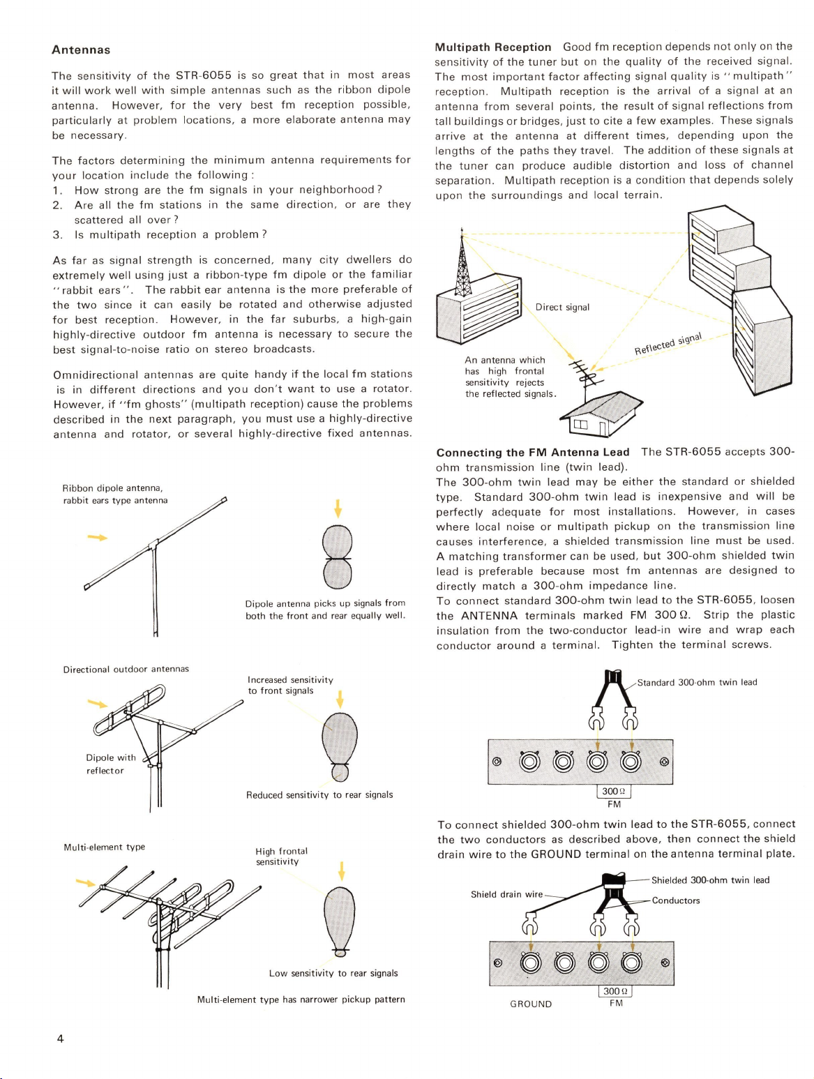
Antennas
Speakers
..........
Record
players
2
2
2
4
5
5
Tape
recorders
. .......... ....
..
..... ....... .........
..
.
.......
.........
..
6
Headphones
....
.....
..
..
.....
.....
..
..
............
......
......... .........
..
6
Ground
connection
Power
connect
ion ... ......
..
......
.........
.
Custom
Mounting
.
.............
......
TAC-5E
cabinet
......
......
.....
.......
Panel
mounting
. .
.......
........
..
.
.....
...
.....
.
OPERATING
INSTRUCTIONS
.........
.
Location
of
Controls
and
Connectors
.. .........
........
...
Function
of
Controls
......................
..
....
How
to
Use
Your
STR-
6055
for
FM
Reception
How
to
Use
Your
STR-6055
for
AM
Reception
Using
Your
STR-6055
with
External
Inputs
..........
..........
6
6
6
6
6
7
7
7
9
9
9
With
a
record
player
................................................... 9
With
a
tape
recorder
.......
..
....... ...................
.......
....
..... 9
Balancing
the
Stereo
System
.. ......................... ... ............
10
Stereo
balance
.
....................
............
.......
... .....
.....
..
.....
10
Speaker
phasing
check
....
..
...........
....
...........................
10
CARE
OF
YOUR
EQUIPMENT
. .........
.....
..
.. ..
..................
.....
10
Cleaning
..................
...... ...
......
.............................
10
Trouble
Checks
.......
... .................................
..
...
..............
10
Repacking
for
Shipment.
..................................... ............
11
TECHNICAL
DATA
..
..
.. .
..
. ......
.....
.............
..
....
........
11
Technical
Specifications
.....
..
..
........................
..
................ 11
Block
Diagram
....
..
...........
...
..
..........
........
...................... .
12