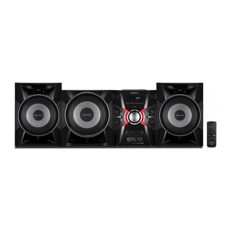
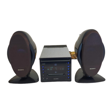
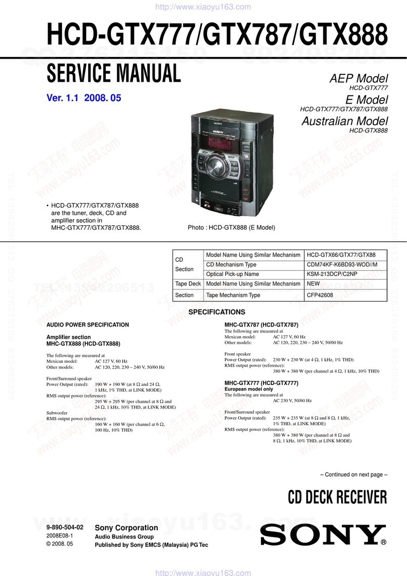
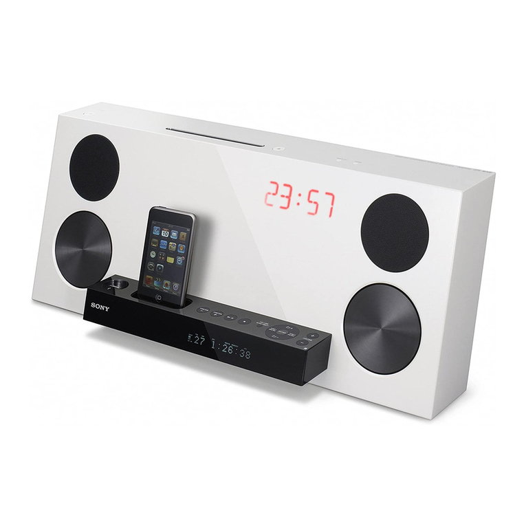
Sony CMT-DF1 User manual

SERVICE MANUAL
ACCESSORIES
Part No. Description Remark
MICRO HI-FI COMPONENT SYSTEM
AEP Model
E Model
Australian Model
CMT-DF1
Ver. 1.2 2007.06
9-887-490-03
2007F05-1
© 2007.06
Sony Corporation
Personal Audio Division
Published by SonyTechno Create Corporation
CMT-DF1
DVD Deck Receiver HCD-DF1
Speaker System SS-CDF1
•CMT-DF1 is composed of following models.
As service manuals are issued for each component model,
please refer to them.
COMPONENT MODEL NAME
1-480-286-11 COMMANDER, STANDARD (RM-SDF1)
1-751-619-13 CORD, CONNECTION (Video cord)
1-754-102-41 ANTENNA, LOOP (LW.MW) (AM loop antenna)
1-754-243-11 ANTENNA (FM lead antenna)
3-272-961-11 MANUAL, INSTRUCTION (ENGLISH)
(AEP, RU, E, HK, SP, TW, AUS)
3-272-961-21 MANUAL, INSTRUCTION (FRENCH, SPANISH) (AEP, E, SP)
3-272-961-31 MANUAL, INSTRUCTION (TRADITIONAL CHINESE)
(HK, SP, TW)
3-272-961-51 MANUAL, INSTRUCTION (KOREAN) (KR)
3-272-961-61 MANUAL, INSTRUCTION (ARABIC) (E)
3-272-961-71 MANUAL, INSTRUCTION (GERMAN, DUTCH) (AEP)
3-272-961-81 MANUAL, INSTRUCTION (SWEDISH, POLISH) (AEP)
3-272-961-91 MANUAL, INSTRUCTION (RUSSIAN) (RU)
3-272-962-11 MANUAL, INSTRUCTION (ITALIAN) (AEP)
•Abbreviation:
AUS:Australian model
HK : Hong Kong model
KR : Korean model
RU : Russian model
SP : Singapore model
TW : Taiwan model
SPECIFICATIONS
Power requirements
European and Russian models:230 V AC, 50/60 Hz
Australian model: 230 – 240 V AC, 50/60 Hz
Korean model: 220 VAC, 60 Hz
Taiwan model: 120 VAC, 50/60 Hz
Other models: 120 V, 220 V, 230 – 240V
AC, 50/60 Hz
Adjustable with voltage
selector
Power consumption: 30 watts
Dimensions (w/h/d) (excl. speakers):
Approx. 169 × 218 ×
201 mm
Mass (excl. speakers) Approx. 2.6 kg
Supplied accessories: Remote Commander (1)
R6 (size AA) batteries (2)
AM loop antenna (1)
FM lead antenna (1)
Video cord (1)
Design and specifications are subject to change
without notice.

CMT-DF1
REVISION HISTORY
Clicking the version allows you to jump to the revised page.
Also, clicking the version at the top of the revised page allows you to jump to the next revised page.
Ver. Date Description of Revision
1.0 2006.11 New
1.1 2007.01 Addition of AEP and Russian models
1.2 2007.06 Addition of detailed content according to servicing form change
(ENG-07003)

SERVICE MANUAL
DVD DECK RECEIVER
HCD-DF1
SPECIFICATIONS
9-887-738-02
2007J05-1
© 2007.10
Sony Corporation
Audio Business Group
Published by Sony Techno Create Corporation
•HCD-DF1 is the amplifier, disc player, tape deck
and tuner section in CMT-DF1.
DVD Model Name Using Similar Mechanism NEW
Section Optical Pick-up Block Name KHM-313AHC
Tape deck Model Name Using Similar Mechanism NEW
Section Tape Transport Mechanism Type H-21
– Continued on next page –
• This system incorporates Dolby1) Digital and DTS2)
Surround System.
1) Manufactured under license from Dolby Laboratories.
“Dolby” and the double-D symbol are trademarks of Dolby
Laboratories.
2) Manufactured under license from Digital Theater Systems, Inc.
“DTS” and “DTS 2.0 + Digital Out” are trademarks of Digital
Theater Systems, Inc.
• MPEG Layer-3 audio coding technology and patents licensed
from Fraunhofer IIS and Thomson.
• DivX is a video file compression technology, developed by
®
developed by DivX, Inc.
DivX, DivX Certified, and associated logos are trademarks of
DivX, Inc. and are used under license.
Digital
Amplifier section
European and Russian models:
DIN power output (rated): 3.6 + 3.6 watts (4 ohms
at 1kHz, DIN)
Continuous RMS power output (reference):
5 + 5 watts (4 ohms at
1 kHz, 10% THD)
Music power output (reference):
8 + 8 watts (4 ohms at
1 kHz, 10% THD)
Other models:
The following measured at AC 120 V, 220 V,
240 V, 50/60 Hz
DIN power output (rated): 3.6 + 3.6 watts
(4 ohms at 1 kHz, DIN)
Continuous RMS power output (reference):
5 + 5 watts
(4 ohms at 1 kHz, 10%
THD)
Inputs
MIC (monaural mini jack): sensitivity 1.5 mV,
impedance 10 kilohms
Outputs
VIDEO OUT (phono jack):max. output level
1 Vp-p, unbalanced,
Sync negative, load
impedance 75 ohms
S VIDEO OUT (4-pin/mini-DIN jack):
Y: 1 Vp-p, unbalanced,
Sync negative,
C: 0.286 Vp-p, load
impedance 75 ohms
COMPONENT VIDEO OUT:
Y: 1 Vp-p, 75 ohms
P
B
, P
R
: 0.7 Vp-p,
75 ohms
DIGITAL OUT (OPTICAL) (Square optical
connector jack, rear panel)
Wavelength 660 nm
PHONES (stereo mini jack):
accepts headphones of
8 ohms or more
SPEAKER: accepts impedance of
4 ohms
Disc player section
System Compact disc and
digital audio and video
system
Laser Laser Diode Properties
•Emission duration:
continuous
•Laser Output*:
Less than 1,000 µW
* This output is the
value measurement
at a distance of
200mm from the
objective lens surface
on the Optical Pick-up
Block with 7mm
aperture.
Semiconductor laser
(DVD: λ=650 nm,
CD: λ=790 nm)
Ver. 1.3 2007.10
AEP Model
E Model
Australian Model

2
HCD-DF1
TABLE OF CONTENTS
1. SERVICING NOTES ............................................... 3
2. GENERAL ................................................................... 5
3. DISASSEMBLY
3-1. Disassembly Flow ........................................................... 6
3-2. Panel Left, Panel Right.................................................... 6
3-3. Cabinet Rear Block ......................................................... 7
3-4. Cabinet Front Block ........................................................ 7
3-5. Mech Deck (H-21), DECK Board ................................... 8
3-6. MAIN Board.................................................................... 8
3-7. OP Assy (KHM-313AHC) .............................................. 9
4. TEST MODE.............................................................. 10
5. MECHANICAL ADJUSTMENTS ....................... 10
6. ELECTRICAL ADJUSTMENT ............................ 11
7. DIAGRAMS
7-1. Block Diagram – MAIN Section – .................................. 13
7-2. Block Diagram
– PANEL/POWER SUPPLY Section – ........................... 14
7-3. Printed Wiring Board – DECK Board – .......................... 16
7-4. Schematic Diagram – DECK Board –............................. 17
7-5. Printed Wiring Board – MICROPHONE Board –........... 18
7-6. Schematic Diagram – MICROPHONE Board – ............. 18
7-7. Printed Wiring Board – MAIN Board – .......................... 19
7-8. Schematic Diagram – MAIN Board (1/4) – .................... 20
7-9. Schematic Diagram – MAIN Board (2/4) – .................... 21
7-10. Schematic Diagram – MAIN Board (3/4) – .................... 22
7-11. Schematic Diagram – MAIN Board (4/4) – .................... 23
7-12. Printed Wiring Board – PANEL Board – ........................ 24
7-13. Schematic Diagram – PANEL Board – ........................... 25
7-14. Printed Wiring Boards – POWER SUPPLY Section –.... 26
7-15. Schematic Diagram – POWER SUPPLY Section – ........ 27
8. EXPLODED VIEWS
8-1. PANEL Section ............................................................... 31
8-2. PANEL Board Section..................................................... 32
8-3. Tape Deck Section ........................................................... 33
8-4. DVD Section ................................................................... 34
8-5. Cabinet Rear Section ....................................................... 35
9. ELECTRICAL PARTS LIST................................ 36
Notes on chip component replacement
•Never reuse a disconnected chip component.
•Notice that the minus side of a tantalum capacitor may be
damaged by heat.
Flexible Circuit Board Repairing
•Keep the temperature of the soldering iron around 270 ˚C
during repairing.
•Do not touch the soldering iron on the same conductor of the
circuit board (within 3 times).
•Be careful not to apply force on the conductor when soldering
or unsoldering.
CAUTION
Use of controls or adjustments or performance of procedures
otherthan thosespecifiedhereinmay resultinhazardous radiation
exposure.
SAFETY-RELATED COMPONENT WARNING!!
COMPONENTS IDENTIFIED BY MARK 0 OR DOTTED LINE
WITH MARK 0ON THE SCHEMATIC DIAGRAMS AND IN
THE PARTS LIST ARE CRITICAL TO SAFE OPERATION.
REPLACE THESE COMPONENTS WITH SONY PARTS WHOSE
PART NUMBERS APPEAR AS SHOWN IN THIS MANUAL OR
IN SUPPLEMENTS PUBLISHED BY SONY.
Frequency response DVD (PCM 48 kHz):
2 Hz −22 kHz (±1 dB)
CD: 2 Hz −20 kHz (±1 dB)
Tape deck section
Recording system 4-track 2-channel stereo
Tuner section
FM stereo, FM/AM superheterodyne tuner
FM tuner section
Tuning range 87.5 −108.0 MHz (50 kHz step)
Antenna FM lead antenna
Antenna terminals 75 ohms unbalanced
Intermediate frequency 10.7 MHz
AM tuner section
Tuning range
Canadian model: 530 −1,710 kHz
Other models: 531 −1,602 kHz
Antenna AM loop antenna
Antenna terminals External antenna terminal
Intermediate frequency 450 kHz
General
Power requirements
European and Russian models:
230 V AC, 50/60 Hz
Australian model: 230 −240 V AC, 50/60 Hz
Korean model: 220 V AC, 60 Hz
Taiwan model: 120 V AC, 50/60 Hz
Other models: 120 V, 220 V, 230 −240V
AC, 50/60 Hz
Adjustable with voltage selector
Power consumption: 30 watts
Dimensions (w/h/d) (excl. speakers):
Approx. 169 ×218 ×201 mm
Mass (excl. speakers) Approx. 2.6 kg
Design and specifications are subject to change
without notice.
This appliance is
classified as a CLASS 1
LASER product. This
marking is located on the
rear exterior.

3
HCD-DF1
MODEL IDENTIFICATION
– Back Panel –
Part No. Model
2-896-838-0[] SP2 Singapore model
2-898-848-0[] CEL AEP model
2-898-850-0[] AU1 Australian model
2-898-852-0[] HK2 Hong Kong model
2-898-853-0[] TW2 Taiwan model
2-898-854-0[] E3 E model
3-217-804-0[] KR2 Korean model
3-268-765-0[] RU1 Russian model
SECTION 1
SERVICING NOTES
NOTES ON HANDLING THE OPTICAL PICK-UP
BLOCK OR BASE UNIT
The laser diode in the optical pick-up block may suffer electrostatic
break-down because of the potential difference generated by the
charged electrostatic load, etc. on clothing and the human body.
During repair, pay attention to electrostatic break-down and also
use the procedure in the printed matter which is included in the
repair parts.
The flexible board is easily damaged and should be handled with
care.
NOTES ON LASER DIODE EMISSION CHECK
The laser beam on this model is concentrated so as to be focused on
the disc reflective surface by the objective lens in the optical pick-
up block. Therefore, when checking the laser diode emission,
observe from more than 30 cm away from the objective lens.
UNLEADED SOLDER
Boards requiring use of unleaded solder are printed with the lead-
free mark (LF) indicating the solder contains no lead.
(Caution: Some printed circuit boards may not come printed with
the lead free mark due to their particular size)
: LEAD FREE MARK
Unleaded solder has the following characteristics.
•Unleaded solder melts at a temperature about 40 °C higher
than ordinary solder.
Ordinary soldering irons can be used but the iron tip has to be
applied to the solder joint for a slightly longer time.
Soldering irons using a temperature regulator should be set to
about 350 °C.
Caution: The printed pattern (copper foil) may peel away if
the heated tip is applied for too long, so be careful!
•Strong viscosity
Unleaded solder is more viscou-s (sticky, less prone to flow)
than ordinary solder so use caution not to let solder bridges
occur such as on IC pins, etc.
•Usable with ordinary solder
It is best to use only unleaded solder but unleaded solder may
also be added to ordinary solder.
PART No.

4
HCD-DF1
You can play back the following discs on this
system. Other discs cannot be played back.
List of playable discs
“DVD VIDEO,” “DVD-R” and “DVD-RW” logos are
trademarks.
Playable discs
Format of discs Disc logo
DVD VIDEOs
DVD-RWs/
DVD-Rs
DVD+RWs/
DVD+Rs
VIDEO CDs
Audio CDs
CD-Rs/CD-RWs
Region code of DVDs you can
play on this system
Your system has a region code printed on the
back of the unit and will only play DVDs labeled
with identical region code.
DVDs labeled will also be played on this
system.
If you try to play any other DVD, the message
“Wrong Region” will appear on the TV screen.
Depending on the DVD, no region code
indication may be labeled even though playing
the DVD is prohibited by area restrictions.
Discs that this system cannot
play
• CD-ROMs (except for extension “.MP3”,
“.JPG” or “.JPEG”)
• CD-Rs/CD-RWs other than those recorded in
the following formats:
−music CD format
−video CD format
−MP3 (MPEG1 Audio Layer-3)/JPEG/DivX
format that conforms to ISO9660*Level 1/
Level 2 or Joliet
• CD-ROMs recorded in PHOTO CD format.
• Data part of CD-Extras
• Super Audio CDs
• DVD-ROMs/DVD-Rs/DVD-RWs/DVD+Rs/
DVD+RWs other than those recorded in
DivX format conforming to Universal Disk
Format (UDF).
• DVD-ROMs/DVD-Rs/DVD-RWs/DVD+Rs/
DVD+RWs recorded in Multi Session
• DVD-RAMs
• DVD Audio discs
• A DVD with a different region code.
• DVD+R DL (Double layer) discs
• DVD+Rs/DVD+RWs recorded in VR (Video
Recording) mode
• Photo-movies created after shooting on a
DVD camcorder in VR (Video Recording
format) mode
• Discs with non-standard shapes (e.g., heart,
square, star) cannot be played on this unit.
Attempting to do so may damage the unit. Do
not use such discs.
• A disc with paper or stickers on it.
• A disc that has the adhesive, cellophane tape,
or a sticker still left on it.
* A logical format of files and folders on a
CD-ROMs, defined by ISO (International
Organization for standardization).
Notes about CD-R/CD-RW/
DVD-R/DVD-RW (Video mode)/
DVD+R/DVD+RW
• In some cases, CD-Rs, CD-RWs, DVD-Rs,
DVD-RWs (Video mode) (DVD-RWs
created in video mode have the same format
as a DVD VIDEO), DVD+R or DVD+RW
cannot be played on this system depending
upon the recording quality or physical
condition of the disc, or the characteristics of
the recording device. Furthermore, the disc
will not play if it has not been correctly
finalized. For more information, see the
operating instructions for the recording
device. Note that some playback functions
may not work with some DVD+RWs/
DVD+Rs, even if they have been correctly
finalized.
• A disc recorded in packet write format cannot
be played.
Note on playback operations
of DVDs and VIDEO CDs
Some playback operations of DVDs and VIDEO
CDs may be intentionally set by software
producers. Since this system plays DVDs and
VIDEO CDs according to the disc contents the
software producers designed, some playback
features may not be available. Also, refer to the
instructions supplied with the DVDs or VIDEO
CDs.
ALL
Music discs encoded with
copyright protection
technologies
This product is designed to playback discs that
conform to the Compact Disc (CD) standard.
Recently, various music discs encoded with
copyright protection technologies are marketed
by some record companies. Please be aware that
among those discs, there are some that do not
conform to the CD standard and may not be
playable by this product.
Note on DualDiscs
A DualDisc is a two sided disc product which
mates DVD recorded material on one side with
digital audio material on the other side.
However, since the audio material side does not
conform to the Compact Disc (CD) standard,
playback on this product is not guaranteed.
Cautions when playing a disc
that is recorded in Multi
Session
• This system can play Multi Session CDs
when an M P3 file (J PEG file ) is contained in
the first session. Any subsequent MP3 files
(JPEG files) recorded in later sessions can
also be played back.
• If audio tracks and images in music CD
format or video CD format are recorded in the
first session, only the first session will be
played back.
• When playing a disc which contains audio
tracks in music CD format, MP3 files and
JPEG files, only the audio tracks in music CD
format can be played back.
• CD-R and CD-RW discs recorded in multi-
session that have not ended by “closing the
session” are not supported.
• With CD-ROMs/CD-Rs/CD-RWs that
contain DivX files in addition to MP3 files or
JPEG files, the system plays only the DivX
files.

5
HCD-DF1
SECTION 2
GENERAL This section is extracted from
instruction manual.
LOCATION OF CONTROLS
Main unit
Cassette compartment qg
Disc compartment 7
DISPLAY qs
Display window 6
DSGX 0
FUNCTION wf
MIC jack 4
MICLEVEL 2
PHONES jack 5
POWER (on/off) 1
PROGRESSIVE qa
Remote sensor 9
STANDBY indicator 3
TUNER/BAND wd
TUNING +/−qf
VOLUME +/−qd
Disc operation buttons
ZOPEN 8
m/M (rewind/fast forward) qf
l/L (go back/forward) qf
x(stop) wa
NX (play/pause) ws
Tape operation button
xZ (stop/eject) qh
X(pause) qj
m/M (rewind/fast forward) qk
N(play) ql
z(record)* w;
* You cannot press zalone.
When you press this button, N
is also pressed.
ALPHABETICAL ORDER
A – O
P – Z
BUTTON DESCRIPTIONS
Remote control
ANGLE 5
AUDIO 4
CLEAR ef
DSGX wf
DVD eh
ENTER qs wg
FM MODE eg
FUNCTION +/−2
MENU/PBC 6
MUTING wh
Number buttons* qf
PAL/NTSC ek
PRESET + wk
PRESET −es
RANDOM qj
REPEAT qg
SEARCH 3
SETUP w;
SUBTITLE wd
TAPE qh
THEATRE SYNC ql
TOP MENU qd
TUNER/BAND wa
TUNER MEMORY ws
TUNING + 9
TUNING −qa
TV e;
TV CH + wk
TV CH −es
TV/VIDEO qk
TV VOL +/−* 7
VOLUME +/−* 7
ZOOM ej
?/1 (on/standby) 1
TV ?/1 1
SLOW/SLOW y8
M(fast forward) 9
X(pause) 0
m(rewind) qa
M/m/</,qs
DISPLAY wj
>(go forward) wk
x(stop) wl
H(play)* ea
.(go back) es
ORETURN ed
-/-- ef
* The H, number 5 and
VOLUME + (TV VOL +)
buttons have tactile dots. Use
the tactile dots as references
when operating the system.
ALPHABETICAL ORDER
A – R
S – Z
BUTTON DESCRIPTIONS

6
HCD-DF1
Note: Follow the disassembly procedure in the numerical order given.
3-2. PANEL LEFT, PANEL RIGHT
SECTION 3
DISASSEMBLY
•This set can be disassembled in the order shown below.
3-1. DISASSEMBLY FLOW
7
two screws
(P2.6
×
8)
8
two screws
(KTP2 3
×
8)
q;
claw
9
claw
qa
claw
qs
panel right
1
two screws
(P2.6
×
8)
3
claw
5
claw
6
panel left
2
two screws
(KTP2 3
×
8)
4
claw
3-2. PANEL LEFT,
PANEL RIGHT
(Page 6)
3-5. MECH DECK (H-21),
DECK BOARD
(Page 8)
3-3. CABINET REAR BLOCK
(Page 7)
3-4. CABINET FRONT BLOCK
(Page 7)
3-7. OP ASSY (KHM-313AHC)
(Page 9)
3-6. MAIN BOARD
(Page 8)
SET

7
HCD-DF1
3-3. CABINET REAR BLOCK
9
cabinet rear block
8
DVD/front cabinet block
6
connector
(CN14)
2
two screws
(KTP2.6
×
6)
3
five screws
(KTP2 3
×
8)
5
connector
(CON10: AEP, RU, E, HK, SP,TW and KR models,
CON501: AUS model)
1
two screws
(P2.6
×
8)
7
connector
(CON5)
4
two screws
(P2.6
×
8)
3-4. CABINET FRONT BLOCK
6
holder (PWB)
7
claw
5
flexible flat cable
(12 core) (CON12)
2
two connectors
(CON2, CON100)
3
connector
(CON9)
q;
cabinet front block
4
connector
(CON1)
1
Remove the solder.
8
claw
9
Push the button (power).
•Abbreviation
AUS:Australian model
HK : Hong Kong model
KR : Korean model
RU : Russian model
SP : Singapore model
TW : Taiwan model

8
HCD-DF1
3
DVD block
7
MAIN board
1
four
connectors
5
flat type wire (9 core)
(MAIN board (CN901), tuner (FM/AM))
4
2
two
screws
(BVTP3
×
8)
6
tune
r
(FM/AM)
3-6. MAIN BOARD
3-5. MECH DECK (H-21), DECK BOARD
q;
holder (PWB)
9
two
screws
(BVTP3
×
8)
2
Cut the clamp.
8
ground lead wire
7
s
crew
(BVTP3
×
8)
4
connector
(CON101)
6
DECK board
5
three
screws
(BVTP2.6)
1
Remove the solder.
3
Cut the clamp.
qa
two
screws
(BVTP3
×
8)
qs
qd
mech deck (H-21)

9
HCD-DF1
5
two screws
(BVTP2.6)
qd
two insulators
qf
OP assy
(KHM-313AHC)
4
flat type wire (24 core
)
(DVD board)
qa
connector
qs
flat type wire (24 core)
(OP assy)
3
sheet
(DVD FFC)
6
DVD board
9
5
two screws
(BVTP2.6)
q;
plate DVD
qd
two
insulators
8
four
screws
(P2
×
10)
1
connector
7
sheet
(DVD wire)
2
connector
3-7. OP ASSY (KHM-313AHC)

10
HCD-DF1
INITIAL MODE SETTING
Procedure:
1. Pressthreebuttonsof[VOLUME +],[DISPLAY] and I/1simultaneously.
2. The system is initialized and turn the power on.
(The function becomes tuner mode and the volume become
16)
SECTION 4
TEST MODE SECTION 5
MECHANICAL ADJUSTMENTS
PRECAUTION
1. Clean the following parts with a denatured-alcohol-moistened
swab :
record/playback head pinch roller
erase head rubber belts
capstan idlers
2. Demagnetize the record/playback head with a head
demagnetizer. (Do not bring the head magnetizer close to the
erase head.)
3. Do not use a magnetized screwdriver for the adjustments.
4. After the adjustments, appiy suitable locking compound to
the parts adjusted.
5. The adjustments should be performed with the rated power
supply voltage unless otherwise noted.
TORQUE MEASUREMENT
Mode Torque Meter Meter Reading
2.0 – 8.0 mN⋅m
FWD CQ-102AS (20 – 80 g⋅cm)
(0.28 – 1.12 oz⋅inch)
FWD 0.15 – 0.6 mN⋅m
Back Tension CQ-102C (1.5 – 6.0 g⋅cm)
(0.021 – 0.083 oz⋅inch)
5.0 – 17.7 mN⋅m
FF CQ-201AS (50 – 177 g⋅cm)
(0.7 – 2.48 oz⋅inch)
5.0 – 17.7 mN⋅m
REW CQ-201B (50 – 177 g⋅cm)
(0.7 – 2.48 oz⋅inch)
TAPE TENSION MEASUREMENT
Mode Tension Meter Meter Reading
FWD CQ-403A more than 80 g
(more than 2.82 oz)

11
HCD-DF1
SECTION 6
ELECTRICAL ADJUSTMENT
0 dB=0.775 VDECK SECTION
1. Demagnetize the record/playback head with a head
demagnetizer.
2. Do not use a magnetized screwdriver for the adjustments.
TEST TAPE
Tape Signal Used for
P-4-A063 6.3 kHz, -10 dB Azimuth Adjustment
RECORD/PLAYBACK HEAD AZIMUTH ADJUSTMENT
Note: Remove the sheet (azimuth) before this adjustment.
After the end of adjustment, try to paste sheet (azimuth) peeled off
to be the same position.
Procedure:
1. Mode: Playback
2. Turn theadjustment screw andcheck outputpeaks. Ifthe peaks
do not match for L-CH and R-CH, turn the adjustment screw
so that outputs match within 1dB of peak.
3. Mode: Playback
set
test tape
P-4-A063
(6.3 kHz, –10 dB) oscilloscope
VH
waveform of oscilloscope
in phase 45
°
90
°
135
°
180
°
good wrong
MICROPHONE board
PHONES jack
(JA302)
Screw
position
L-CH
peak
within
1dB
Output
level
L-CH
peak R-CH
peak
within
1dB
Screw
position
R-CH
peak
set
MICROPHONE board
PHONES jack
(JA302)
+
–
level mete
r
test tape
P-4-A063
(6.3 kHz, –10 dB)
4. After the adjustments, apply suitable locking compound to
the pats adjusted.
Adjustment Location: Record/Playback/Erase Head

12
HCD-DF1
MEMO

1313
HCD-DF1
HCD-DF1
7-1. BLOCK DIAGRAM – MAIN Section –
JAC5
SPEAKER
L
R
T101
BIAS OSC
R-CH
BIAS OSC
Q25, 27
: AUDIO
: VIDEO
SIGNAL PATH
R-ch is omitted due to same as L-ch.
: Y
: CHROMA
: COMPONENT VIDEO
: DIGITAL OUT
: TUNER (FM/AM)
: TAPE PLAY
: REC
: MIC INPUT
TAPE MECHA
DECK BLOCK
DVD BOARD
VIDEO OUT
JAC1
DIGITAL OUT
OPTICAL
S VIDEO OUT
JAC2
JAC3
COMPONENT
VIDEO OUT
Y
P
B
/C
B
P
R
/C
R
CY
PB
REC
SW5 (5/9)
(REC/PB)
PB
REC
SW5 (4/9)
(REC/PB)
PB
REC
SW5 (3/9)
(REC/PB)
PB
REC
SW5 (2/9)
(REC/PB)
PB
REC
SW5 (1/9)
(REC/PB)
5 2
MUTING
Q301
IN1 OUT1
7
ALC_IN
6ALCOUT1
MUTING
Q26
BIAS
TRAP
R-CH
R-CH
PB
REC
SW5 (8/9)
(REC/PB)
B+ SWITCH
Q23, 24 +9V
D10
D9
D18D19
FAN MOTOR A
POWER MUTING B
D31
D12
D301
D11
REC/PB AMP, ALC
IC4
5SDA
6SCL
EEPROM
U2
+
TUNER (FM/AM)
AM
FM ANT
AM ANT
TU-L
TU-R
TU-DO
R-CH
TU-DATA
TU-CLK
TU-CE
FM 75Ω
COAXIAL
ANTENNA
6 DVD_STB/TU_DO
14
18
DVD-L
17 LINLOUT
23MUTE
24O-LCH13 TU-L
15
26
TA-L
DATA
27
27 26
CLK
FILTER
STANDBY
VCC_CTRL C
5 7
29 OP/CL
12 PROTECT
10 DVD_IR/TU_DI
24C01_DATA/7314_DATA
24C01_CLK/7314_CLK
9DVD_CLK/TU_CLK
11 DVD_DATA/TU_CE
OPTICAL
TRANSCEIVER
JAC4
MUTING
CONTROL SWITCH
Q3
MUTING
SWITCH
Q4
LINE AMP
Q16
VR301
MIC LEVEL
JA303
MIC
MIC AMP
IC301 (2/2)
R-CH
R-CH
MIC AMP
IC301 (1/2)
MUTING
Q13
STANDBY
SWITCH
Q11
10 IN1
POWER AMP
IC101
1OUT1 JA302
PHONES
SYSTEM CONTROLLER
U1 (1/2)
INPUT SELECTOR, ELECTRICAL VOLUME
IC102
SECTION 7
DIAGRAMS
(Page 14)
(Page 14)
(Page 14)

1414
HCD-DF1
HCD-DF1
7-2. BLOCK DIAGRAM – PANEL/POWER SUPPLY Section –
REMOTE CONTROL
RECEIVER
IC5
LCD1
LIQUID
CRYSTAL
DISPLAY
LIQUID CRYSTAL
DISPLAY DRIVER
IC2
SYSTEM CONTROLLER
U1 (2/2)
RESET SWITCH
Q1
B+ SWITCH
Q5, 7
7RESET
25POWER_CTRL
28DVD_VCC_CTRL
SEG1 –
SEG30
12 – 15 17 – 46
KEY_IN0 –
KEY_IN2
13 – 15
COM1 –
COM4
30 STAND_BY
5 REMOTE
LED3
STANDBY
LED1, 2
(LCD BACK LIGHT)
2
XOUT
3
XIN
XT1
4.19MHz
SD_DATA BU9728_DATA9 21
SCK BU9728_CLK8 18
CS BU9728_CE10 20
C/D_STB BU9728_C/D_STB11 22
RESET +4V
OPTION_IN
16
17
16 KEY_OUT
KEY1 – KEY11
(AC IN)
D4
D39
D36, 37
D17
D34
F2
RECT
D24 – 27
F3
RECT
D20 – 23
F1
DVD+5V
T1
POWER
TRANSFORMER
Abbrivation
: Hong Kong modelHK
: Singapore modelSP
: Australian modelAUS
D1
SW1
POWER
SW1
POWER
(EXCEPT AUS)
(AUS)
(E, HK, SP)
(EXCEPT E, HK, SP)
(AUS)
VOLTAGE
SELECTOR
SW2
+4V
+9V
DVD+9V B+ SWITCH
Q21
SWITCHING
REGULATOR
U3
+9V
REGULATOR
IC1
+4V
REGULATOR
Q8
POWER OFF
MUTING
Q6
POWER OFF
MUTING
Q19
FAN MOTOR
A
POWER
CONTROL
Q9
24TU_VCC_CTRL VCC_CTRL
C
POWER MUTING
B
POWER
CONTROL
Q20
FAN MOTOR
DRIVE
QT2, QT4
M1
(FAN)
M
FAN MOTOR
DETECT
QT3
Q2
B+ SWITCH
Q22
(Page 13)
(Page 13)
(Page 13)

1515
HCD-DF1
HCD-DF1
MICROPHONE board
PANEL board
DECK board
POWER SWITCH board
MAIN board
TUNER (FM/AM)
DVD board
POWER board
•Note for PrintedWiring Boards and Schematic Diagrams
C
BThese are omitted.
E
Q
Note on Schematic Diagram:
•All capacitors are in µF unless otherwise noted. (p: pF)
50 WV or less are not indicated except for electrolytics
and tantalums.
•All resistors are in Ωand 1/4W or less unless otherwise
specified.
•C: panel designation.
•A: B+ Line.
•Voltages and waveforms are dc with respect to ground
under no-signal (detuned) conditions.
no mark :TUNER (FM/AM)
():DVD PLAY
[]: TAPE PLAY
〈〈 〉〉 : REC
∗: Impossible to measure
•Voltagesare takenwithaVOM (Inputimpedance 10MΩ).
Voltage variations may be noted due to normal produc-
tion tolerances.
•Waveforms are taken with a oscilloscope.
Voltage variations may be noted due to normal produc-
tion tolerances.
•Circled numbers refer to waveforms.
•Signal path.
F: AUDIO
L: VIDEO
E:Y
a: CHROMA
r: COMPONENT VIDEO
J: DIGITAL OUT
f: TUNER (FM/AM)
d: TAPE PLAY
G: REC
N: MIC INPUT
•Abbreviation
AUS:Australian model
HK : Hong Kong model
KR : Korean model
RU : Russian model
SP : Singapore model
TW :Taiwan model
•Circuit Boards Location
Note on PrintedWiring Board:
•X: parts extracted from the component side.
•Y: parts extracted from the conductor side.
•x: parts mounted on the conductor side.
•: Pattern from the side which enables seeing.
(The other layers' patterns are not indicated.)
•Indication of transistor
Note: The components identified by mark 0or dotted line
with mark 0are critical for safety.
Replace only with part number specified.
B
These are omitted.
CE
Q

1616
HCD-DF1
HCD-DF1
7-3. PRINTED WIRING BOARD – DECK Board – •See page 15 for Circuit Boards Location. : Uses unleaded solder.
•Semiconductor
Location
Ref. No. Location
D11 C-2
D12 C-2
D13 D-5
D14 D-5
D15 B-5
D16 B-5
IC4 C-4
Q23 A-2
Q24 B-2
Q25 E-4
Q27 E-4
ZD5 B-5
(Page 19)
J101
J102
J103
R184
R177
J111
R193
C197
W2
J112
J113
R165
J109
L101
J108
J107
C173
J106
CON101
C192
J105 J104
C178
L102
C176
C174
C172
C193
C180
C188
J110
ZD5
C194
C195
IC4
C175
C191
C177
C187
C179
J114
C230
C233
C234
C235 J115
T101
C171
R194
Q23
R195
R196
Q24
C198
R197
R188
D11
D12
R178
R186
R185
R187
R139
C237
C232
R168
Q27
R169
R181
R179
C189
RJ100
R182
C190
R176
R180
C169
R172
C203
R174
C184
C186
R183
D15
D16
C170
C183
R173 C185
R171
R175
D14
D13
R170
C231
R167
R166
Q25
C238
C9
DECK BOARD
E
E
E
E
1-874-332-
11
(11)
A
MAIN
BOARD
CON1
1
1
3
7
148
-1
-2
-3
-4
-5
-6
-7
-8
-9
SW5
(REC/PB)
REC
PB
1
11
(CHASSIS)
BIAS
OSC
TAPE MECHA
DECK BLOCK
(1/2)
A
B
C
D
E
F
1 2 3 4 5

1717
HCD-DF1
HCD-DF1
(Page 20)
7-4. SCHEMATIC DIAGRAM – DECK Board – •See page 28 for IC Block Diagrams.
C183 C185
C171
R173
C175
C170
C173
C193
R183
C184
R174
C172
C169
C176
R176
C180
C9
C174
C194
C186
C195
C192
R182
C190
L102
RJ100
R181
C189
R169
C237
C231 C230
R188
C197
ZD5
D11
C234
C233 R167
R166
C232
Q25
Q27
R184
R186
R185
R139
R195
R196
Q23
R194
CON101
IC4
T101
R172
R180
C188
R197
C198
SW5(4/9)
SW5(5/9)
SW5(6/9)
SW5(7/9)
R177
R168C191
C187
R187
C179
R171 R175 C177
D13 D14
L101
D15
C178
R170
C238
R179
D16
C235
R165
R193
R178
SW5(8/9)
SW5(1/9)
SW5(3/9)
SW5(2/9)
SW5(9/9)
Q24
W2
C203
D12
20p 100p
4.7
50V
56k
100
16V
100p
0.0033
47
16V220k
20p
56k
4.7
50V
100p
100
16V
6.8k
10
50V
100p
0.0033
220
16V
100p
470
16V
0.0033
8.2k
390p
0
8.2k
390p
5.6k
100p
0.022 220
16V
1.5k
47
16V
MTZJ-T-77-6.8B
RLS4148
0.022
0.01 12k
33k
470p
2SC3052
2SC3052
47
220k
220k
560
22k
2.2k
2SC3052
4.7k
3P
LA3220
33
47k
4.7
50V
2.2k
0.1
10.0033
4.7
50V
1.5k
10
50V
33 6.8k 0.022
RLS4148 RLS4148
RLS4148
0.022
5.6k
100p
47k
RLS4148
330p
22
1k
0
ISA1235
100p
RLS4148
MUTE
VCC CONT
9V
AGND
PLAY-R
REC-R
REC-L
PLAY-L
SW
MUTE
PROT
ALC_IN
DC
ALC_OUT
ALC_OUT2
IN1
NF1
PC1
OUT1
GND
VCC
OUT2
PC2
NF2
IN2
BIAS OSC
BIAS OSC
Q25,27
REC/PB AMP,ALC
(REC/PB)
REC
PB
REC
PB
(REC/PB)
REC
PB
(REC/PB)
REC
PB
(REC/PB)
REC
PB
(REC/PB)
REC
PB
(REC/PB)
REC
PB
(REC/PB)
REC
PB
(REC/PB)
REC
PB
(REC/PB)
Q23,24
B+ SWITCH
(CHASSIS)
TAPE MECHA
DECK BLOCK
(1/2)
1
11
10µH
10µH
J107
100

1818
HCD-DF1
HCD-DF1
7-6. SCHEMATIC DIAGRAM – MICROPHONE Board –
JA302
CE304
CE302
J303 CE303
CE301
VR301
JA303
J301
J302
R301
C309
C310
R302
C305
C311
R308
R313
Q301
R305
C307
C302
R303
R304
R306
C301
C303
R307
D301
R317
R316
C306
IC301
R309
C304
R315
R310
R314
R311
E
1-874-333-
11
(11)
C
MAIN BOARD
CON2
B
MAIN
BOARD
CON100
MICROPHONE BOARD
PHONES MIC
MIC LEVEL
15
1
5
A
B
C
1 2 3 4 5
R304Q301 C302
CE303
R313
CE301
R308
CE304
R317
IC301(1/2)
C306 CE302 R316
C303
C301R306
R309
C305
C304
IC301(2/2)
R305 C307 R303
D301
R310
R311
R314
R307
R301
R302
JA303
JA302
C310
C309
C311
VR301
R315
100k2SC3052 0.0022
10
16V
100k
10
16V
2.2k
100
10k
NJM14558M
0.1 100
16V 8.2k
1
82p100k
100k
1
470p
NJM14558M
4.7k 0.47 4.7k
RLS4148
22k
27k
470
270
270
270
20K
100
0.01
0.01
1000p
GND
SP-L
SP-R
PH-L
PH-R
MIC-VCC
MIC-IN
GND
MIC
MIC AMP
1
4
7
8
5
6
3
2
PHONES
MUTING
MIC LEVEL
M-MUTE
M-MUTE
1
1
5
5
: Uses unleaded solder.
7-5. PRINTED WIRING BOARD – MICROPHONE Board –
•See page 15 for Circuit Boards Location.
(Page 21)
(Page 19)
(Page 20)
(Page 19)
Other manuals for CMT-DF1
2
Table of contents
Other Sony Stereo System manuals

Sony
Sony GTK-X1BT User manual

Sony
Sony HCD-VX777 User manual

Sony
Sony ZS-S10CP User manual

Sony
Sony MAP-S1 User manual

Sony
Sony HCD-EC55 - Receiver System User manual

Sony
Sony ZS-XN30 - Cd Boombox User manual

Sony
Sony SRS-X2 User manual

Sony
Sony CMT-EP315 User manual

Sony
Sony ZS-X3CP Marketing Specifications & Features User manual

Sony
Sony MHC-G100 User manual

Sony
Sony CHC-TB10 User manual

Sony
Sony MHC-RXD9 - 3 Cd Mini System User manual

Sony
Sony MHC-DX3 User manual

Sony
Sony DHC-MD5 User manual

Sony
Sony HCD-EX1 User manual

Sony
Sony MHC-V42D User manual

Sony
Sony HCD-H991AV User manual

Sony
Sony MHC-VX55 User manual

Sony
Sony HCD-ZX70DVD User manual

Sony
Sony HCD-441 User manual