Amplifier
section
Peak
music
power
output
1000
W
Continuous
RMS
power
output
68
+
68
W
(6
ohms
at
1
kHz,
5%
THD)
Inputs
AUX
IN:
Sensitivity
450
mV,
impedance
47
kilohms
Outputs
PHONES
(stereo
phone
jack):
accept
headphones
of
8
ohms
or
more.
SPEAKER:
accept
impedance
of
6
to
16
ohms.
SURROUND
SPEAKER:
accept
impedance
of
16
ohms.
(Singapore,
Malaysia,
Mexican
model)
accept
impedance
of
8
to
16
ohms.
(EXCEPT
Singapore,
Malaysia,
Mexican
model)
Speaker
section
Speaker
system
3-way
system
Speaker
units
Woofer:
15
cm
dia.,
cone
ae
Dimensions;
Frequency
range
60
Hz
-
20
kHz
Sensitivity
87
dB/W/m
Rated
impedance
6
ohms
Dimensions
Approx.
210
x
325
x
250
mm
(w/h/d)
Mass
Approx.
3.6
kg
net
per
speaker
Supplied
accessories
AM
loop
aerial
(1)
Remote
(1)
Sony
SUM-3
(NS)
batteries
(2)
FM
lead
aerial
(1)
Speaker
cables
(2)
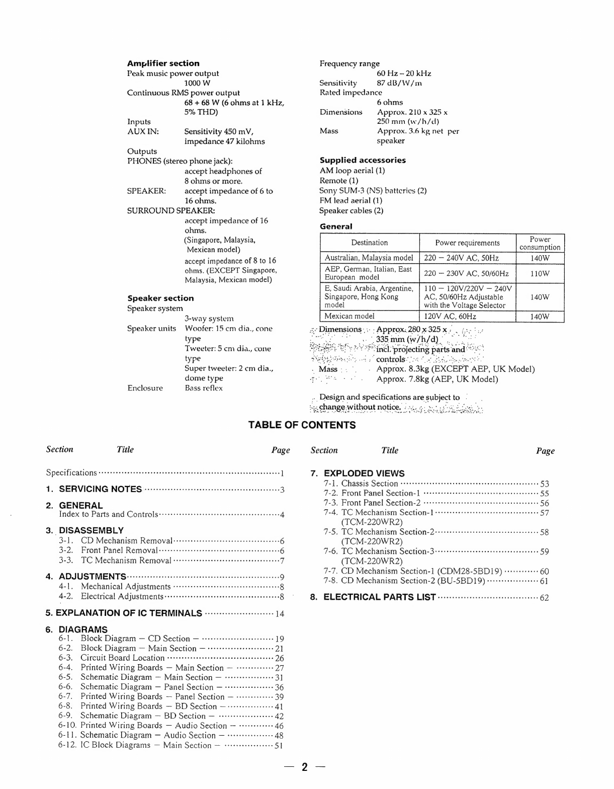
General
.
Power
Destination
Power
requirements
.
q
consumption
Australian,
Malaysia
model
|
220
—
240V
AC,
50Hz
140W
AEP,
German,
Italian,
East
—
230V
AC,
50/60Hz
LOW
European
model
E,
Saudi
Arabia,
Argentine,
|
110
—
120V/220V
—
240V
Singapore,
Hong
Kong
AC,
50/60Hz
Adjustable
140W
model
with
the
Voltage
Selector
120V
AC,
60Hz
140W
-;
Approx..280
x
325
x
;
type
i
(335
mm
(w/h/d)
|
Tweeter:
5
cm
dia.,
cone
YP
ined:
Piejecing
parts
and’
ae
type
Seitetee
sts”
controls.
Super
tweeter:
2
cm
dia.,
.
Mass:.°.
-
Approx.
8.
3kg
(EXCEPT
‘AEP,
UK
Model)
dome
type
“ss
4°.
Approx.
7.8kg
(AEP,
UK
Model)
Enclosure
Bass
reflex
.
Design
and
Leis
are
vee
to
2
4.
change-without
notice.
¢s4.6:
eu
Shiva
TABLE
OF
CONTENTS
Section
Title
Page
Section
Title
Page
Specifications
*+++++-2+cesssecccerseenvervsvesovsensnnsccsensnosaasveneseness
l
7.
EXPLODED
VIEWS
ey
rae
SE
st
ao
aaa
ad
odode
aa
aa
alee
hsneza
SSulese
Weds
$3
1:
SERVICING
NOTES
&
0m
.sseevecteeceeev
eens
vcceseesastesereneonss
3
WD
Fane Rael
SE
toil
wae
se
Sela
aheousstseeasadopedsccd
55
7-3.
Front
Panel
Section-2
Pome
merece
eee
e
eee
ee
ee
es
ee
eeeeseeeeeese
56
.
Macnee
Aue
COLES
LSKe
ee
roneria
Aehe
enon
nae
4
TAo
TC
Mechanism
Secon
|
-ettatwatetieesrentecdscacapetss
57
(TCM-220WR2)
3.
DISASSEMBLY
7-5.
TC
Mechanism
Section-2:etrrerssesetereeeeereeeceeeseeeenes
58
CME
BIEMU
(rc
er
Cr
wot
ite
Ror
reer
reer
eer
eee
6
(TCM-220WR2)
3-9
“Front
Panel
Renrvoval
esnxtsscavenvssgass
anenararsraiersacens
6
9.6
TC
Mechanisin:
SEGHOIe
3818)
oie
end
Aiton
sasencadocceaerebecn
59
3-3
"TOC
Mechanisin
Removal
os
errsavmnon
eaves
ees
tecdeenes
a
(TCM-220WR2)
7-7.
CD
Mechanism
Section-1
(CDM28-5BD19)
+1+++++++++
60
4.
ADJUSTMENTS
:---
ede’
ya
Wh
acne
onmeaoes
sada
Ba
Ghua
le
se
Seameoeesas
Fi
9
7-8.
CD
Mechanism
Section:
24
BU-SBDI9)
es
cuewnes
61
4-1.
Mechanical
Adjustments
eee
eee
cece
ene
n
erect
reece
ee
eereseeeees
8
4-2.
Electrical
Adjustments++++++++++++ssessereseceeceseesenennees
8
8.
ELECTRICAL
PARTS
LIST
--:-:::ccccecsecececeentenee
enter
es
62
5.
EXPLANATION
OF
IC
TERMINALS
------+-+----+-esseeee
14
6.
DIAGRAMS
6-1.
Block
Digeram==
CD
Séetion
=
sesieaeteictintians
19
6-2.
Block
Diagram
—
Main
Section
—
:rrrrrrrersereeee
seen
21
6-
3
Circuit
Board
Location
Pee
mere
rene
recor
oeseeeereeessessene
26
6-4.
Printed
Wiring
Boards
—
Main
Section
—
-+++++++++++-
27
6-5.
Schematic
Diagram
—
Main
Section
—
srrrre+eseeeeee
ee
3]
6-6.
Schematic
Diagram
—
Panel
Section
—
-+r++++ereeeeee
ee
36
6-7.
Printed
Wiring
Boards
—
Panel
Section
—
-+++++++++++-
39
6-8.
Printed
Wiring
Boards
—
BD
Section
—-+++++++++eeeeee
41
6-9.
Schematic
Diagram
—
BD
Section
—
-rrrrseeeee
eres
eee
42
6-10.
Printed
Wiring
Boards
—
Audio
pechery
Fe
Meese
NSN
eS
46
6-L1.
Schematic
Diagram
—
Audio
Section
—
++++rrrereereee
48
6-12.
IC
Block
Diagrams
—
Main
Section
—
-++++e+eeeeeeeee
|