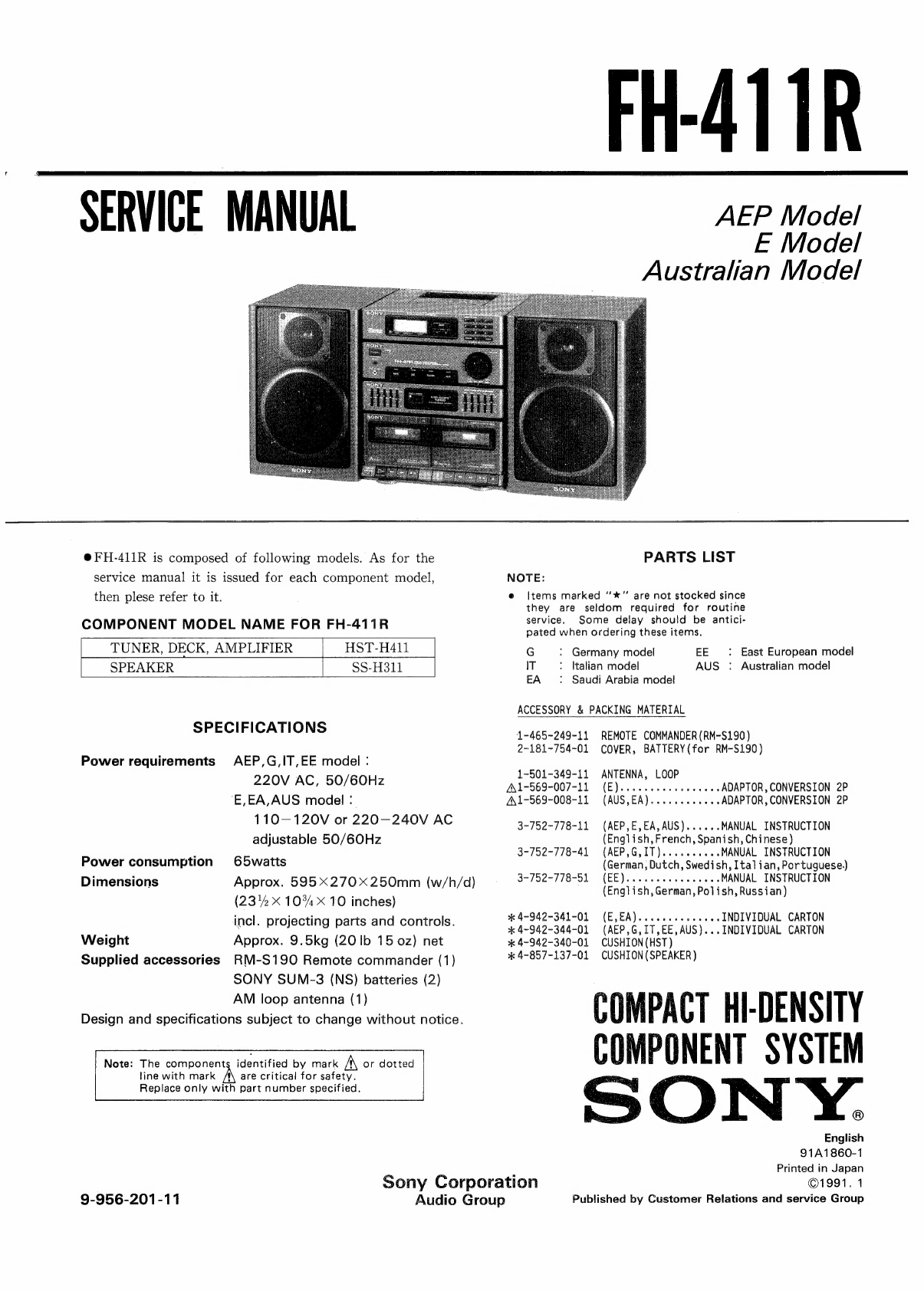
Sony FH-411R User manual
Other Sony Stereo System manuals

Sony
Sony CMT-M70 Primary User manual

Sony
Sony CMT-HP7 - Executive Microsystem User manual

Sony
Sony LBT-XGV10AV User manual

Sony
Sony HCD-H881 User manual
 User manual")
Sony
Sony 3-287-077-14(2) User manual

Sony
Sony HCD-V808 User manual

Sony
Sony ZS-RS60BT User manual

Sony
Sony HCD-DX10 User manual

Sony
Sony HCD-VX33 User manual

Sony
Sony CMT-EH45DAB User manual

Sony
Sony LBT-D107 User manual

Sony
Sony CMT-CP555 User manual

Sony
Sony LBT-D260 User manual

Sony
Sony CMT-MD1 - Micro Hi Fi Component System User manual

Sony
Sony WHG-SLK1i - Audio System Component User manual

Sony
Sony SA-VE702 User manual

Sony
Sony LBT-G2000 User manual

Sony
Sony MHC-3500 - Mini Hi-fi Bookshelf System User manual

Sony
Sony ZS-X7 Primary User manual

Sony
Sony CMT-NEZ30 User manual