– 3 –
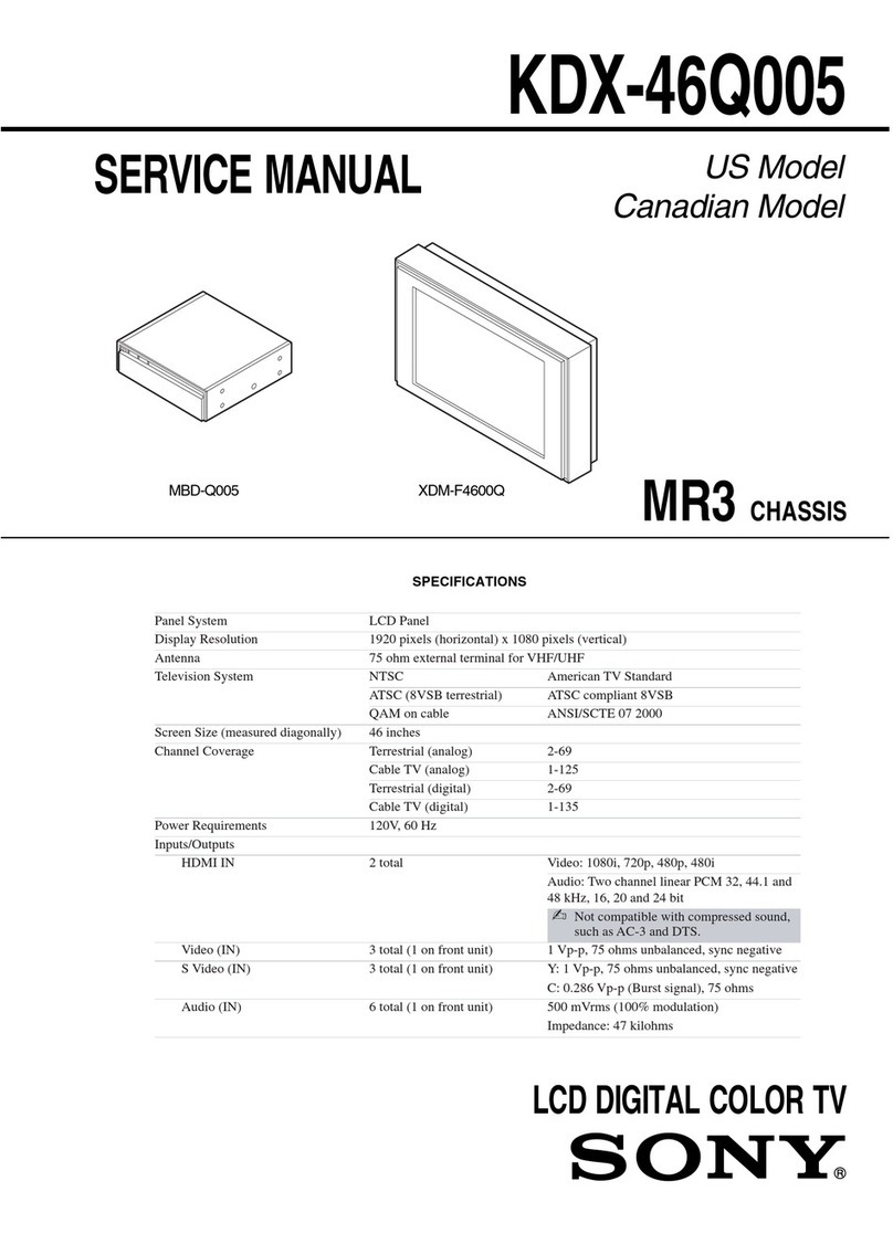
KV-EF29M31/EF29M61/EF29M80/RM-881
EF29M90/EF29M91/EF29M80/RM-881
1. GENERAL ................................................................. 4
2. DISASSEMBLY
2-1. Rear Cover Removal ......................................... 22
2-2. Speaker Box Assy Removal .............................. 22
2-3. Chassis Assy Removal ...................................... 22
2-4. Service Position ................................................. 22
2-5. Terminal Bracket, Power Holder,
DH Bracket Removal ........................................ 23
2-6. Picture Tube Removal ........................................ 24
2-7. Wiring Harness Layout ...................................... 25
3. SET-UP ADJUSTMENTS................................... 26
3-1. Beam Landing ................................................... 26
3-2. Convergence ...................................................... 27
3-3. Focus Adjustment .............................................. 30
3-4. G2 (Screen) and White Balance Adjustments ... 31
4. SELF DIAGNOSIS FUNCTION ..................... 32
5. CIRCUIT ADJUSTMENTS ................................ 33
5-1. Adjustments with Commander ......................... 33
5-2. Adjustment Method ........................................... 34
5-3. Picture Quality Adjustments ............................. 39
5-4. Display Position Adjustments ........................... 39
5-5. A Board Adjustment After IC003
(MEMORY) Replacement ................................ 40
TABLE OF CONTENTS
6. DIAGRAMS
6-1. Block Diagrams .................................................. 41
6-2. Circuit Boards Location ..................................... 54
6-3. Schematic Diagrams and Printed Wiring
Boards ................................................................. 55
(1) Schematic Diagram of A Board ........................ 59
(2) Schematic Diagrams of H7, J, P3 and
P4 Boards ........................................................... 64
(3) Schematic Diagrams of B3, C1, V3 and
VM Boards ........................................................ 75
(4) Schematic Diagrams of D, D2 and
DH Boards ......................................................... 80
(5) Schematic Diagrams of A3, A5 and
S1 Boards ........................................................... 88
6-4. Semiconductors ................................................. 93
7. EXPLODED VIEWS
7-1. Speaker Box ...................................................... 95
7-2. Chassis ............................................................... 96
7-3. Picture Tube ...................................................... 97
8. ELECTRICAL PARTS LIST ............................ 98
Section Title PageSection Title Page
