TABLE
OF
CONTENTS
1.
GENERAL
{ef2.
“Gerierals.
66.4
Sia
Sree
Seah
th
el
ee
Beard
Saas
1-2.
Connections.
..
2...
ee
eee
ee
ee
es
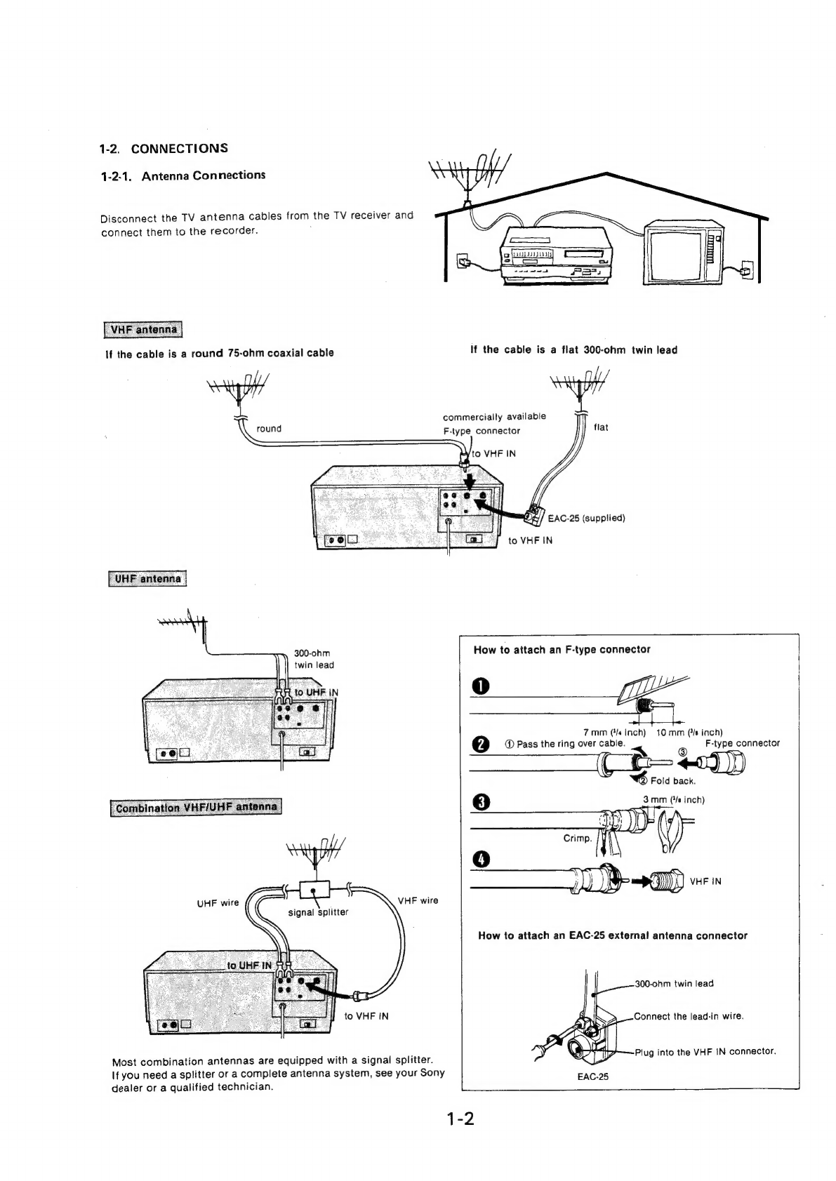
1-2-1.
Antenna
Connections............-....2005.
1-2-2.
Connecting
the
TV
Receiver...
..........----
1-2-3.
Connections
to
a
Cable
TV
(CATV)
System.
.......
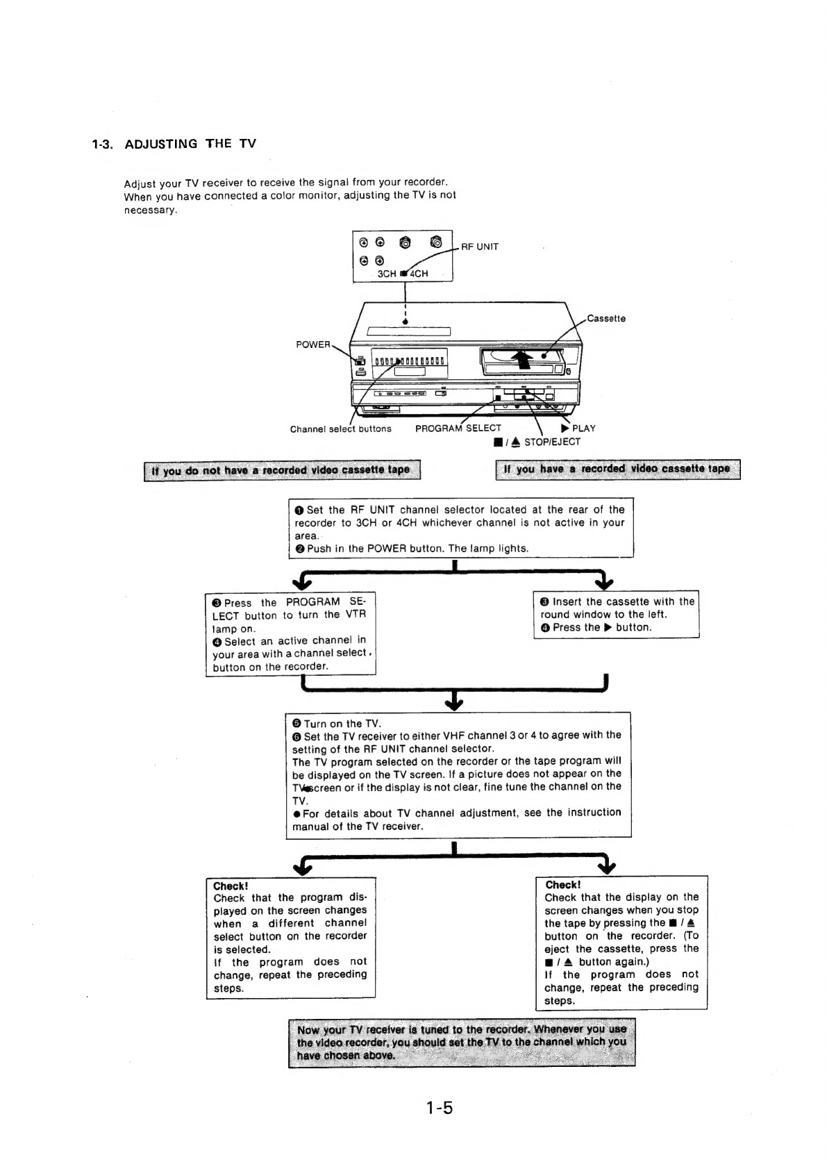
1-3.
Adjusting
the
TV...
2.0...
2.
ee
eee
eee
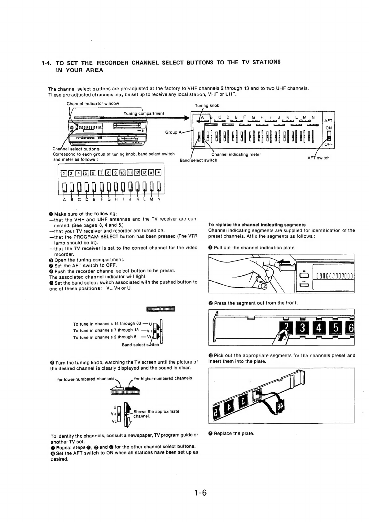
1-4.
To
Set
the
Recorder
Channel
Select
Buttons
to
the
TV
Stationsin
Your
Area...
2...
....000
002005
1-5.
Disassembly
.-.-
2-2.
ee
ee
ee
ee
.
Cabinet
Removal...
2.0...
2.0...
eee
ees
1-5-2.
Timer/Tuner
Block
Removal
..............-..
.
Check
of
VA-1
and
SS-9
Boards...
2.2...
ee
ee
.
Upper
Drum
Removal...
2...
20-02-0000
0-005
1-6.
Location
of
PartsandControls.............-.
BLOCK
DIAGRAMS
Overall
Block
Diagram
Video
System
Block
Diagram
........6..2005
Servo
System
Block
Diagram
.............--.-
Drum
Servo
Timing
Chart
.........-.-.....-..
Capstan
Servo
Timing
Chart
(61)
Capstan
Servo
Timing
Chart
(@M)
...........--
Capstan
Servo
Timing
Chart
(GMI)
............-
Tape
Speed
Auto
Matic
Timing
Chart
(1)
.........
Tape
Speed
Auto
Matic
Timing
Chart
(2)
System
Control
Block
Diagram
System
Control
Timing
Chart
............0--
Audio
Block
Diagram
...............0006.
Audio
Level
Diagram
............
02000005
Timer
&
Power
Supply
Block
Diagram
Tuner
IF
Block
Diagram
SAFETY-RELATED
COMPONENT
WARNING
!!
COMPONENTS
IDENTIFIED
BY
SHADING
AND
MARK
A
ON
THE
SCHEMATIC
DIAGRAMS,
EXPLODED
VIEWS
AND
IN
THE
PARTS
LIST
ARE
CRITICAL
TO
SAFE
OPERATION.
REPLACE
THESE
COMPONENTS
WITH
SONY
PARTS
WHOSE
PART
NUMBERS
APPEAR
AS
SHOWN
IN
THIS
MANUAL
OR
IN
SUPPLEMENTS
PUBLISHED
BY
SONY.
CIRCUIT
ADJUSTMENTS
THAT
ARE
CRITICAL
TO
SAFE
OPERATION
ARE
IDENTI-
FIED
IN
THIS
MANUAL.
FOLLOW
THESE
PRO-
CEDURES
WHENEVER
CRITICAL
COMPONENTS
ARE
REPLACED
OR
IMPROPER
OPERATION
IS
SUSPECTED.
DIAGRAMS
Frame
Schematic
Diagram...
2...
2...
....008.
VAT?
RP-5:
Boards:
«3.4.3
esis
Se3
ere
ed
ao
Serene
SS-9,
FG-2,
DR-1, DR-2,
DR-3, DR-4, DR-5,
DR-6,
DR-7, DR-8,
DR-9,
DR-10,
FS-11,
FS-12,
FL-2,
TT-2,
TT-3,
TT-4,
TT-5,
SL-1,
CP-6
Boards
LF-21,
TP-2,
TP-3,
TP-4,
TP-6
Boards
IF-16,
TU-23
Boards
.......-.
00000002
eee
RM-59W
Remote
Control
Unit
EXPLODED
VIEWS
Front
Assembly
Cabinet
Assembly
...........
200000
eee
eee
Cassette
Loading
Assembly
(1)
Cassette
Loading
Assembly
(2)
Function
Assembly
.........
0000002
ee
ree
Tuner/Timer
Assembly
........-....00+
0005
Tuner/Power
Assembly
........-...0
00000
Drum
Assembly.
=
6
sa.
%
s0
kB
ee
Oe
Chassis
Assembly
(1)
Chassis
Assembly
(2)
Chassis
Assembly
(3)
Chassis
Assembly
(4)
Chassis
Assembly
(5)
2...
eee
ee
ee
es
Lower
Frame
Assembly
..........-..0-
00005
Remote
Control
Unit
ELECTRICAL
PARTS
LIST
ATTENTION
AU
COMPOSANT
AYANT
RAPPORT
A
LA
SECURITE!!
LES
COMPOSANTS
IDENTIFIES
PAR
UN
TRAME
ET
UNE
MARQUE
A\
SUR
LES
DIAGRAMMES
SCHEMA-
TIQUES,
LES
VUES
EXPLOSEES
ET
LA
LISTE
DES
PIECES
SONT
CRITIQUES
POUR
LA
SECURITE
DE
FONCTIONNEMENT.
NE
REMPLACER
CES
COMPO-
SANTS
QUE
PAR
DES
PIECES
SONY
DONT
LES
NUMEROS
SONT
DONNES
DANS
CE
MANUEL
OU
DES
SUPPLEMENTS
PUBLIES
PAR
SONY.
LES
REGLAGES
DU
CIRCUIT
QUI
SONT
CRITIQUES
POUR
LA
SECURITE
DE
FONCTIONNMENT
SONT
IDENTIFIES
DANS
CE
MANUEL.
SUIVRE
LES
PROCEDURES
QUAND
LES
COMPOSANTS
CRITIQUES
SONT
REMPLACES
OU
LE
FONCTIONNEMENT
IMPROPRE
EST
SUSPECTE.