manuals.online logo
Brands
  1. Home
  2. •
  3. Brands
  4. •
  5. Sony
  6. •
  7. VCR System
  8. •
  9. Sony SLV-789HF - Video Cassette Recorder User manual

Sony SLV-789HF - Video Cassette Recorder User manual

SLV-789HF/792HF/799HF
RMT-V267A
SERVICE MANUAL
c
Photo: SLV-799HF
RMT-V267A
US Model
SLV-789HF/799HF
Canadian Model
SLV- 789HF/792HF/799HF
Refer to the SERVICE MANUAL of VHS
MECHANICAL ADJUSTMENT VI for
MECHANICAL ADJUSTMENTS. (9-921-647-11)
SPECIFICATIONS
CM
tvhs
SMECHANISM
i
v
System
Format
VHS NTSC standard
Video recording system
Rotary head helical scanning FM system
Video heads
Double azimuth four heads
Video s;ignal
NTSC color, EIA standards
Tape speed
SP: 3335 mm/s (1 7» inches/s)
EP: 11.11 mm/s (Vis inches/s)
IP: 16.67 mm/s ("A* inches/s),
playback only
Maximum recording/playback time
8hrs. in EP mode (with T-160 tape)
Fasl:-forward and rewind rime
Approx. 3min. (with T-120 tape)
Tuner section
Channel coverage
VHF 2to 13
UHF 14 to 69
CATV A-8 to A-l, Ato W, W+l to W+84
Antenna
re-ohm antenna terminal for VHP/UHF
Inputs and outputs
LINE-1 IN and -2 IN
VIDEO IN, phono jack (1 each)
Input signal: 1Vp-p, 75 ohms, unbalanced,
sync negative
AUDIO DM, phono jacks (2 each)
Input level: 327 mVrms
Input impedance: more than 47 kilohms
LINE OUT
VIDEO OUT, phono jack (1)
Output signal: 1Vp-p, 75 ohms, unbalanced,
sync negative
AUDIO OUT, phono jacks (2)
Standard output: 327 mVrms
Load impedance: 47 kilohms
Output impedance: less than 10 kilohms
S-LDMK (CONTROL SIN)( SLV-792HP7799HF)
Mini jack (1)
CABLE BOX CONTROL (CONTROL SOUT)
Stereo mini jack (plug in power) (1)
Timer section
Clock
Quartz locked
Timer indication
12-hour cycle
Timer setting
8programs per month (max.)
Power back-up
Built-in self-charging capacitor
Back-up duration: up to 1hour at atime
General
Power requirements
120 VAC, 60 Hz
Power consumption
24 W
Operating temperature
5oCto40°C(41°Ftol04°F)
Storage temperature
-20°C to 60°C H°F to 140°F)
Dimensions
Approx. 430 x100 x292.5 mm (w/h/d)
(Approx. 17 X4X11 5/« inches) including
projecting parts and controls
Mass
Approx. 4.1 kg (9 lb 1oz)
Supplied accessories
Remote commander (1)
Size AA (R6) batteries (2)
75-ohm coaxial cable with F-type connectors (1)
Audio/video cable (3-phono, 1-mini to 3-phono,
1-mini) (1) (SLV-792HF7799HF)
Cable Mouse (cable box controller) (1)
(SLV-797HF/799HF)
Design and specifications are subject to change
without notice.
ENERGY STAR Is aUS. registered mark.
As an ENERGY STAR Partner, Sony Corporation
has determined that this product meets the
ENERGY STAR guidelines for energy efficiency.
VIDEO CASSETTE RECORDER
TABLE
SERVICE NOTE
1.ERROR CODE INDICATION •
1. GENERAL
Getting Started
Unpacking
Selling up the remote commander
Hookups
Selecting alanguage
Setting the clock
Setting up the cable box control I
Presetting channels 1
Setting up the VCR Plus+ GOLD system 1
Basic Operations
Playing atape 1
Recording TV programs 1
Locating achannel by Station ID 1
Recording TV programs using
the VCR Plus+ GOLD system 1
Setting the timer manually I
Additional Operations
Playing/searching at various speeds I
Searching for aselected point on the tape I
Skip-searching automatically 1
Creating afavorite channel list with Station ID 1
Recording TV programs using the dial timer 1
Setting the recording duration time 1
Checking/changing/eanceling timer settings I
Recording stereo and bilingual programs I
Searching using the index function 1
Adjusting the picture 1
Changing menu options 1
Editing with another VCR 1
Additional information
General setup information 1
Index to parts and controls 1
I-I
1-2
1-9
1-9
11
12
14
16
17
18
-18
-19
-20
-20
-21
-21
-22
-23
-2 i
-23
-24
-24
-25
-25
-26
-26
2.
2-1.
2-2.
2-3.
2-4.
2-5.
2-6.
2- 7.
3.
3- 1.
3-2.
3-3.
3-4.
3-5.
41.
4-2.
DISASSEMBLY
CASE. FRONT PANEL BLOCK ASSEMBLY
ME-316 BOARD. DM-84 BOARD, DI-71 BOARD
REAR PANEL
MA-342 BOARD
MECHANISM DECK
INTERNAL VIEWS
CIRCUIT BOARDS LOCATION
•2-1
•2-1
.2-2
2-2
2-3
2-4
•2-5
BLOCK DIAGRAMS
OVERALL BLOCK DIAGRAM
VIDEO BLOCK DIAGRAM
SERVO/SYSTEM CONTROL/TUNER
BLOCK DIAGRAM
AUDIO BLOCK DIAGRAM
POWER BLOCK DIAGRAM
3-1
3-3
•3-5
3-7
3-9
PRINTED WIRING BOARDS AND
SCHEMATIC DIAGRAMS
FRAME SCHEMATIC DIAGRAM
PRINTED WIRING BOARDS AND SCHEMATIC
DIAGRAMS
•MA-342 (VIDEO. AUDIO. SERVO/SYSTEM
CONTROL/TUNER) PRINTED WIRING BOARD
•MA-342 (1/8) (REC7PB AMP) SCHEMATIC
DIAGRAM
•MA-342 (2/8) (VIDEO/AUDIO) SCHEMATIC
DIAGRAM
•MA-342 (3/8) (SERVO/SYSTEM CONTROL)
cn 11:\iATir 'hi \/—n \\1
4-3
4-5
4-5
4-7
49
OF CONTENTS
•MA-342 (5/8) (TUNEiR) SCHEMATIC
.4DIAGRAM
•MA-342 (6/8) (ERONT) SCHEMATIC
DIAGRAM
•MA-342 (7/8) (POWER SUPPLY) SCHEMATIC
,DIAGRAM
•MA-342 (8/8) (V SET) SCHEMATIC DIAGRAM
•DM-84 (TAPE. OPERATION) PRINTED
WIRING BOARD
•DM-84 (TAPE OPERATION) SCHEMATIC
DIAGRAM
•ME-3 16 (POWER, EJECT SWITCH) PRINTED
WIRING BOARD
•ME-3 16 (POWER, EJECT SWITCH) SCHEMATIC
DIAGRAM 4
•DI-71 (DIAL TIMER SWITCH) PRINTED WIRING
BOARD AND SCHEMATIC DIAGRAM 4
•AR-20 (ARC) PRINTED WIRING BOARD AND
SCHEMATIC DIAGRAM 4
15
-17
19
4-23
4-24
4-25
26
27
28
5. INTERFACE, IC PIN FUNCTION
DESCRIPTION
5-1 .SYSTEM CONTROL —MECHANISM BLOCK
INTERLACE (MA-342 BOARD IC160)
5-2. SYSTEM CONTROL —SERVO PERIPHERAL
CIRCUIT INTERFACE (MA-342 BOARD KM 60)
5-3. SYSTEM CONTROL —SYSTEM CONTROL
PERIPHERAL CIRCUIT INTERFACE
(MA-342 BOARD ICI60)
5-4. SYSTEM CONTROL AND RF MODULATOR
-INPUT SELECTION BLOCK INTERFACE
(MA-342 BOARD ICI60)
5-5. SYSTEM CONTROL -VIDEO/RP BLOCK
INTERFACE (MA-342 BOARD IC160)
5-6. SYSTEM CONTROL -AUDIO BLOCK INTERFACE
(MA-342 BOARD IC160)
5-7. SERVO/SYSTEM CONTROL MICROPROCESSOR
PIN FUNC TIONS (MA-342 BOARD IC160)
5-1
5-1
5-2
5-2
5-2
5-2
5-3
6. ADJUSTMENTS
6-1 MECHANICAL ADJUSTMENTS
6-2. EI ICIRI( \l. ADJUSTMENTS
2- 1.PREPARATION BEFORE ADJUSTMENT
2-1-1. Equipment Required
2- 1-2. Equipment Connection
2- 1-3. Set-up of Adjustment
2-1-4. Alignment Tape
2- 1-5. Input/Output Levels and Impedance
2- 1-6. Adjustment Sequence
2-2. POWER SUPPLY CHECK
2-2- 1. Output Voltage Check (MA-342 Board)
2-3. SERVO SYS TEM CHECK
2-3-1. RF Switching Position Adjustment (MA-342 Board)
2-4. AUDIO SYSTEM ADJUSTMEN T
2-4- 1.Hi-Fi Audio System Adjustment (Hi-Fi model only)
2-4-2. Hi-Fi Switching Position Adjustment
(MA-342 Board)
24-3. Normal Audio System Adjustment
2-4-4. ACT; Head Adjustment
2-4-5. E-F Output Level Check
2-4-6. Frequency Response Check
2-5. ADJUSTING PARTS LOCATION DIAGRAM
6-1
•6-1
6-1
•6-1
•6-1
•6-
1
6-1
6-2.
6-2
6-2
6-2
6-3
6-3
6-3
6-3
6-4
6-4
6-4
6-4
-6-4
6-6
7. REPAIR PARTS LIST
7-1 EXPLODED VIEWS
7-1-1. FRONT PANEL AND UPPER CAST: SEC TION
7-1-2. CHASSIS SECTION
•7-
1
-7-1
-7-2
SAFETY CHECK-OUT
After correcting the original service problem, perform the following
safety checks before releasing the set to the customer.
1.Check the area of your repair for unsoldered or poorly-soldered
connections. Check the entire board surface for solder splashes
and bridges.
2. Check the interboard wiring to ensure that no wires are
"pinched" or contact high-wattage resistors.
3. Look for unauthorized replacement parts, particularly
transistors, that were installed during aprevious repair. Point
them out to the customer and recommend their replacement.
4. Look for parts which, though functioning, show obvious signs
of deterioration. Point them out to the customer and
recommend their replacement.
5. Check the line cord for cracks and abrasion.
Recommend the replacement of any such line cord to the
customer.
6. Check the B+ voltage to see it is at the values specified.
7. Check the antenna terminals, metal trim, "metallized" knobs,
screws, and all other exposed metal parts for AC leakage.
Check leakage as described below.
To Exposed Metal
Parts on Set
0.15 \iF±. ?.6A1>
AC
Voltmeter
(0.75 V)
... Earth Ground
Fig. A. Using an AC voltmeter to check AC leakage.
LEAKAGE TEST
The AC leakage from any exposed metal part to earth ground and
from all exposed metal parts to any exposed metal part having a
return to chassis, must not exceed 0.5mA (500 microampers).
Leakage current can be measured by any one of three methods.
1.Acommercial leakage tester, such as the Simpson 229 or RCA
TW-540A. Follow the manufacturers' instructions to use these
instruments.
2. Abattery-operated AC milliammetcr. The Data Precision 245
digital multimeter is suitable for this job.
3. Measuring the voltage drop across aresistor by means of a
VOM or battery-operated AC voltmeter. The "limit" indication
is 0.75V, so analog meters must have an accurate low voltage
scale. The Simpson 250 and Sanwa SH-63Trd are examples
of apassive VOM that is suitable. Nearly all battery operated
digital multimeters that have a2V AC range are suitable. (See
Fig. A)
SAFETY-RELATED COMPONENT WARNING!!
COMPONENTS IDENTIFIED BY MARK AOR DOTTED LINE WITH
MARK AON THE SCHEMATIC DIAGRAMS AND IN THE PARTS
LIST ARE CRITICAL TO SAFE OPERATION. REPLACE THESE
COMPONENTS WITH SONY PARTS WHOSE PART NUMBERS
APPEAR AS SHOWN IN THIS MANUAL OR IN SUPPLEMENTS
ATTENTION AU COMPOSANT AYANT RAPPORT
ALA SECURITE!
LES COMPOSANTS IDENTIFES PAR UNE MARQUE ASUR LES
DIAGRAMMES SCHEMATIQUES ET LA LISTE DES PIECES SONT
CRITIQUES POUR LA SECURITE DE FONCTIONNEMENT. NE
REMPLACER CES COMPOSANTS QUE PAR DES PIESES SONY
DONT LES NUMEROS SONT DONNES DANS CE MANUEL OU
n>»no Ito <M inncmCMTO Ol ml IPC PAP C.ANV
SERVICE NOTE
1. ERROR CODE INDICATION
»Error codes arc indicated using the lower 5digits in the fluorescent display tube.
"At this time. Colon between character is not indicated."
en mMode code indication when the error lias occurred.
Hrror code
ERROR CODE
0No error
ICam encoder error Loading direction
2Cam encoder error Unloading direction
i. Treel error
4Sreel error
^. Capstan error
6Drum error
7Error on initializing
8Cassette loading error
9Reserve
MODE CODE
0Power-on eject 10 FWD x120 REW play
Power-on initial 1 1 FWD x2 21 Cas. loading
Power-off eject 12 CUE 22 Tape loading
Power-off stop 13 PB-pause 23 Power-off loading
4FF 14 RVS-pausc 24 Mecha. error (Power on)
5REW 15 RVS xl 25 Power-on eject initial
(> REC 16 RVS x2 26 Power-off eject initial
7RFC- pause 17 REV 27 APC REC
8Power-on stop 18 Power-off initial 28 Cas. loading
(No auto PB check)
9PB 19 Mecha. error (Power off)
SECTION 1
GENERAL
SLV-789HF/792HF/799H F
This section is extracted from
instruction manual.
Getting Started
Unpacking
Check that you have received the following items with the VCR:
•Remote commander 'Cable Mouse (cable box controller)
Si«AA(R6) batteries 75-ohm coaxial cable with F-type
connectors
1Audio/video cable (3-phono, 1-mini
to 3-phono, 1-mini)
Setting up the remote commander
Inserting the batteries
Insert two size AA (R6) batteries
by matching the +and -on the
batteries to the diagram inside the
battery compartment.
Insert the negative (-) end first,
then push in and down until the
positive (+) end clicks into position.
Using the remote commander Remote sensor
You can use this remote
commander to operate this VCR
and aSony TV or AV receiver.
Burtons on the remote
commander marked with adot
(•) can be used to operate your
Sony TV.
The RECEIVER VOL +/- and
MUTING buttons can be used to
operate your Sony AV receiver.
'a a'a
CD CD CD CD
'0 '© '©
'© 'CD ©
'CD '© '®
"© O.RECEIVER VOL +/-
To operate Set jTvl (RECEIVER^ V1PEO| to
aSony
orAV r
[TVl[RF.CE:i VER3and point at the remote sensor on the TV o
receiver
Getting Started |
!
4IGetting Started
Step 2: Setting up the remote commander (continued)
Notes
•With normal use, the batteries should last about three to six months.
•If you do not use the remote commander for an extended period of time, remove
the batteries to avoid possible damage from battery leakage.
•Do not use anew battery wilh an old one.
•Do not use different types of batteries.
•Some Sony AV receivers may not be operated with the remote commander.
Controlling other TVs with the remote commander
The remote commander is preprogrammed to control non-Sony TVs. If your
TV is listed In the table below, set the appropriate manufacturer's code
number.
1Set Ll^l^ErVERl/IVIDEOl al the top of the remote commander to
Trvl [recfiverI
2Hold down 1/(1), and enter your TV's code number(s) using the number
buttons. Then release I/C!).
Now you can use the 1/6, VOL +/-, CH +/-, and TV/VIDEO buttons to
control your TV. You can also use the buttons marked with adot(*) to
control aSony TV. To control the VCR, reset Fi"V [[RECEIVERS/ IVlDEOlto
LVIDjjOj
.
Code numbers of controllable TVs
If more than one code number is listed, try entering them one at atime until
you find the one that works with your TV.
Manufacturer Code
number Manufacturer Code
number
Sony 01 JVC 09 RCA 04, 10
Akai 04 KMC 03 Sampo 12
aoc 04 Magnavox 03, 08, 12 n
Centurion 12 Marantz 04, 13 Scott 12
Coronado 03 MGA/Mitsubishi 04, 12, 13, 17 Sears 07, 10, 11
Curis-Mathes 12 NEC 04, 12 03, 05, 18
Daytron 12 Panasonic 06, 19 Sylvania 08, 12
03, 04, 14 I'hUco 03,04 Teknika 03, 08, 14
11 Philips OS Toshiba 07
General Electric 06,10 Pioneer 16 Wards 03, 04, 12
GoldStar 03, 04, 17 Portland 03 Yorx 12
Hitachi 02,03 Quasar 06, 18 15
J.C.Penny 04, 12 Radio Shack 05, 14
Notes
•If Ore TV uses adifferent remote control system from the one pro£iammed If) work
with the VCR, you cannot control your TV with the remote commander.
•If you enter a new code number, the rode number previously entered will be erased
•When you replace the batteries of the remote commander, the code number may
change. Set the appropriate code number every time you replace the batteries.
Step 3
Hookups
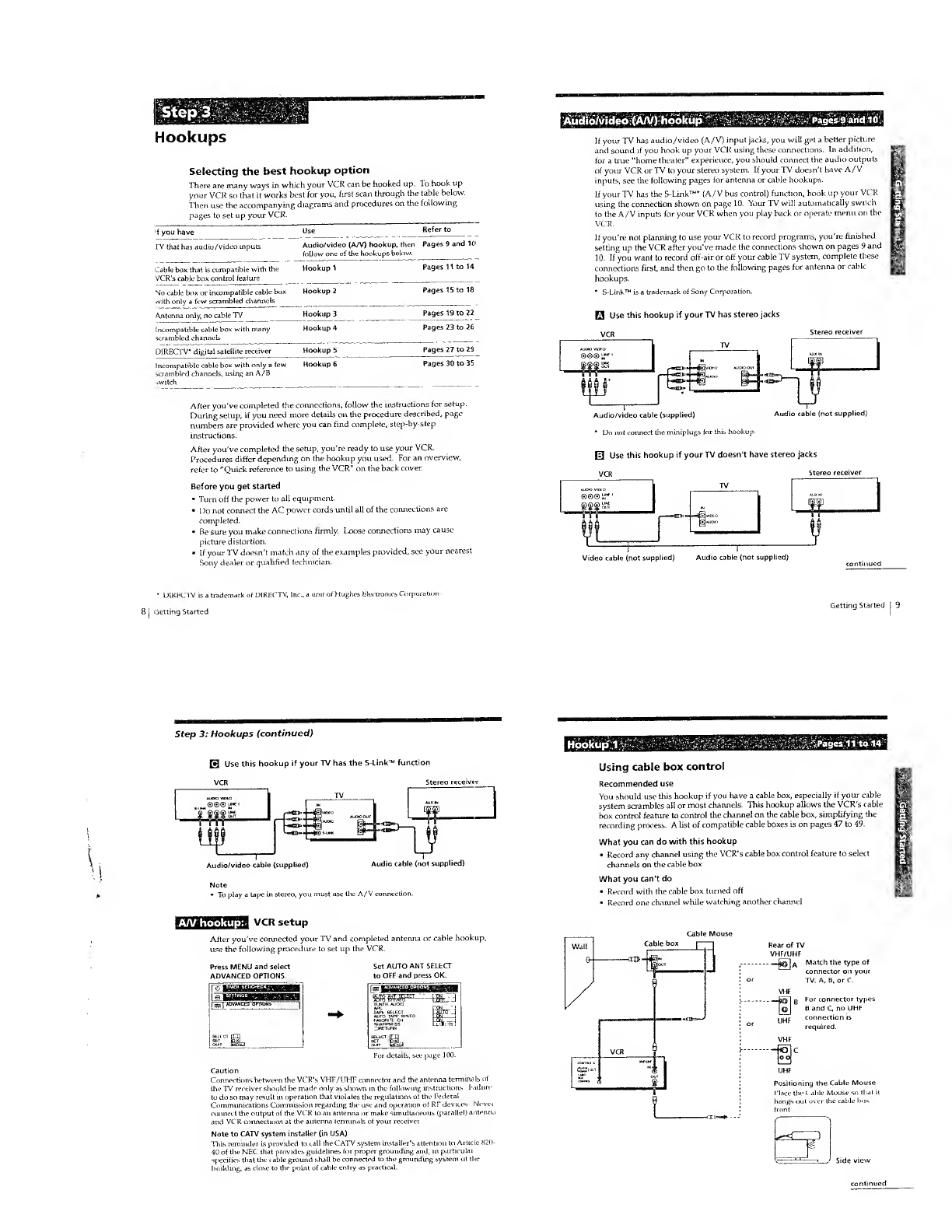
Selecting the best hookup option
There are many ways in which your VCR can be hooked up. To hook up
your VCR so that Uworks best for you, first scan through the table below.
Then use the accompanying diagrams and procedures on the following
pages to set up your VCR.
fyou have Use Refer to
rV that has audio/video inputs Audio/video (A/V) hookup, then
follow one of the hookups below.
Pages 9and 10
Cable box that is compatible with the
VCR's cable box control feature
Hookup 1Pages 11 to 14
cable box or incompatible cable box
with only afew scrambled channels
Hookup 2Pages 15 to 18
Antenna only, no cable TV Hookup 3Pages 19 to 22
Incompatible cable box with many
scrambled channels
DIRECTV* digital satellite receiver
Hookup 4
Hookup 5
Pages 23 to 26
Pages 27 to 29
Incompatible cable box with only afew Hookup 6Pages 30 to 35
:r ambled channels, using an A/B
After you've completed the connections, follow the instructions for setup.
During setup, if you need more details on the procedure described, page
numbers are provided where you can find complete, step-by-step
instructions.
After you've completed the setup, you're ready to use your VCR.
Procedures differ depending on the hookup you used. For an overview,
refer to "Quick reference to using the VCR" on the back cover.
Before you get started
•Turn off the power to all equipment.
•Do not connect the AC power cords until all of the connections are
completed.
"Be sure you make connections firmly. I,oose connections may cause
picture distortion.
•If your TV doesn't match any of the examples provided, see your nearest
Sony dealer or qualified technician.
Audio/video (A/V) hookup Pages 9and 10
If your TV has audio/video (A/V) input jacks, you will get abetter picture
and sound if you hook up your VCR using these connections. In addition,
for a true "home theater" experience, you should connect the audio outputs
of your VCR or TV to your stereo system. If your TV doesn't have A/V
inputs, see the following pages for antenna or cable hookups.
If your TV has the S-Link™* {A/V bus control) function, hook up your VCR
using the connection shown on page 10. Your TV will automatically switch
to the A/V inputs for your VCR when you play back or operate menu on the
VCR.
If you're not planning to use your VCR to record programs, you're finished
setting up the VCR after you've made the connections shown on pages 9and
10. If you want to record off-air or off your cable TV system, complete these
connections first, and then go to the following pages for antenna or cable
hookups.
*S-Link™ is atrademark of Sony Corporation.
HUse this hookup if your TV has stereo jacks
Stereo receiver
©S© u
Audio/video cable (supplied)
*Do not connect the miniplugs (or this hookup.
Audio cable (not supplied)
0Use this hookup if your TV doesn't have stereo jacks
VCR Stereo receiw
Video cable (not supplied) Audio cable (not supplied)
•OlRJ-XrVV is atrademark of DIRECTV, In.
Getting Started
in it of Hughes Electronics Corpoi
Getting Started
Step 3: Hookups (continued)
HUse this hookup if your TV has the S-Link™ function
VCR Stereo n
Audio/video cable (supplied) Audio cable (not supplied)
A/V hookup:
To play atape in stereo, you must use the A/V connection.
VCR setup
After you've connected your TV and completed antenna or cable hookup,
use the following procedure to set up the VCR.
Press MENU and select
ADVANCED OPTIONS.
Set AUTO ANT SELfcCT
to OFF and press OK.
For detail:.,
Caution
Connections between the VCR's VHF/UHF connector and the antenna termina Is
the TV receiver should be made only as shown in the following instructions Kiih
to do so may result in operation that violates the regtilatic
Communications Commission regarding the use and opei
connect the output of the VCR to an antenna or make sun
and VCR connections at the antenna terminals of your rec
Note to CATV system installer (in USA)
This reminder is provided to call the CATV system install
40 of the NEC that provides guidelines for proper grounding and,
specifies that the cable ground stall be connected to the grounding sy:
building, as close to the point of cable entry as practical.
if the 1-e
nof RI:devices. Wevei
.eous (parallel) a.uenn.
to Article 820-
Hpofcup 1.'-.Pages 11 to 14
Using cable box control
Recommended use
You should use this hookup if you have acable box, especially if your cable
system scrambles ail or most channels. This hookup allows the VCR's cable
box control feature to control the channel on the cable box, sunplifying the
recording process. Alist of compatible cable boxes is on pages 47 to 49.
What you can do with this hookup
•Record any channel using the VCR's cable box control feature to select
channels on the cable box
What you can't do
•Record with the cable box turned off
•Record one channel while watching another channel
Rear of TV
VHF/UHF
--_£@n AMatch the type of
connector on your
TV: A, B, or C.
VHF
--—pi] BFor conr,ector types
[q| Band C, no UHF
U^jp connection is
required.
VHF
Positioning the Cable Mouse
Place the C. able Mouse so that it
hangs out over the cable box
Side view
continued
Step 3: Hookups (continued)
ookiip 1: VCR setup
Set the RF UNIT switch to
CH3 or CH4, whichever
channel is not used in your
area. If both are used, set the
switch to either channel.
For details, see page 104.
If you made A/V
connections (from page 9),
you can skip this step.
Turn on your cable box.
Press EASY SET UP on the VCR.
OThe LANGUAGE menu appears. Change the
on-screen display language to Spanish
(ESl'ANOL) or French (FRANCAIS) if desired,
and press OK. For details, see page 36.
OThe CLOCK SET menu appears. Select AUTO
and press OK. For details, see page 38
OThe SMART CHANNEL MAPPING menu
appears. Press t/i/*-/^ to enter the ZIP/
POSTAL CODE in your area and press OK. (You
can also use the number buttons to enter the
ZIP/POSTAL CODE.)
©The CABLE BOX CONTROL menu appears
Select ON. For details, see page 46.
if] era
0Enler your cable box code number and press
OK. For details, see page 46.
©Select your cable box output channel and press OK.
Hookup 1
Norma! display
The VCR Plus+ GOLD system channel setup
1Press MENU, then select SETTINGS and press Irjrj
2Select SET VCR IJlus+ CHANNELS and press
OK.
3Select AUTO and press OK
4Press to turn off the VCR.
12 jGetting Started
Hookup 2Pages IS to 18
.Step 3: Hookups (continued)
The VCR receives the program information signal from 0:00 am to 5:00 am
while the VCR is turned off, and set up the channel for the VCR PIus+
GOLD system recording. After channel setup is finished, you can record TV
programs using the VCR Plus+ GOLD system. For details, see page 59.
Notes
•To use the Smart Channel Mapping feature, leave the cable box on.
•It takes about 1hour to complete channel setup.
•The VCR can receive the program information signal only while the VCR is turned
off and no timer recordings are set,
If the channels in your area don't carry the program information signals, sot the
program guide channels manually For details, see page 62.
«If the CHOOSE YOUR CABLE CH MAP menu appears the first time you turn on
the VCR after finishing channel setup, select the MAP number. For details, see
page 61.
Automatic dock setting
Once you've set up the VCR, it automatically sets the clock the first time you
turn off the VCR. After that, whenever you turn off the VCR, it checks the
time and adjusts the clock, even for Daylight Saving Time. The VCR sets the
clock by picking up atime signal provided by some TV channels.
If you want to use the timer to record right away, or if the channels in your
area do not carry time signals, set the clock manually. For details, see
page 4.1
l) use the Auto Clock Set fea leave the cable box on.
No cable box, or incompatible cable box with only a
few scrambled channels
Recommended use
Use this hookup if you do not have acable box. Also use this hookup if your
cable company cannot supply acable box that is compatible with the VCR's
cable box control feature, and your cable system scrambles only a few
channels.
What you can do with this hookup
•Record any unscrambled channel by selecting the channel on the VCR
What you can't do
Record scrambled channels that require acable box
Connect this cable
directly to your TV if
you don't have
cable box. iCable
~S' Match the type
of connector on
your TV: A, B, or
C.
For connector
types Band C,
no UHF
connection is
required.
Step 3: Hookups (continued)
Hookup 2: VCR setup
1Set the RF UNIT switch to
CH3 or CH4, whichever
channel is not used in your
area. If both are used, set
the switch to either channel.
For details, see page 104.
If you madeA/V
connections (from page 9),
you can skip this step.
2Press EASY SOT UP on
the VCR.
OThe LANGUAGE menu appears. Change the
on-screen display language to Spanish
(ESPANOL) or French (FRANCA1S) if desired,
and press OK. For details, see page 36.
©The CLOCK SET menu appears. Select AUTO
and press OK. For details, see page 38.
0The SMART CI IANNE1.MAPPING menu
appears. Press i//"/- to enter the ZIP/
POSTAL CODE in your area and press OK. (Yen
can also use the number buttons fo enter the
ZIP/POSTAL CODE.)
OThe CABLE BOX CONTROL n
Select OFF and press OK.
Getting Started
0The TUNER PRESET menu appears. Set
ANTENNA/CABLE to CABLE and press OK.
For details, see page 52.
0The AUTO PRESET starts.
Hookup 2:
Normal display
The VCR Plus+ GOLD system channel setup
Press MENU, then select SETTINGS and press
OK. [a! BC, ™as 71
famJjjjHjjlg
SCLECI .[LL1
oofr SiemjI
2Select SET VCR Plus* CHANNELS and press
OK.
3Select AUTO and press OK.
4Press 1/6 to him off the VCR.
Getting started
•Hookup 3Pagefr19to22
Step 3: Hookups (continued)
The VCR receives the program information signal from 0:00 am to 5:00 am
while the VCR is turned off, and set up the channel for the VCR Plus *
GOLD system recording. After channel setup is finished, you can record TV
programs using the VCR Plus+ GOLD system. For details, see page 59.
Notes
•It takes about 1hour to complete channel setup.
•The VCR can receive the program information signal only while the VCR is turned
off and no timer recordings are set.
•If the channels in your area don't carry the program information signals, set the
program guide channels manually. For details, see page 62.
•If the CHOOSE YOUR CABLE CH MAP menu appears the first time you turn on
the VCR after finishing channel setup, select the MAP number. For details, so'
page 61.
Automatic clock setting
Once you've set up the VCR, it automatically sets the clock the first time you
turn off the VCR. After that, whenever you turn off the VCR, it checks rhe
time and adjusts the clock, even for Daylight Saving Time. The VCR sels the
clock by picking up atime signal provided by some TV channels.
If you want to use the timer to record right away, or if the channels in your
area do not carry time signals, set the clock manually. For details, see
page 43.
Antenna hookup
Make the following connections if you're using an antenna (if you don't
have cable TV).
El Use this hookup if you're using:
•VHF/UHF antenna (you get channels 2-13 and channels 14 and higher)
•UHF-only antenna (you get channels 14 and higher)
•Separate VHP and UHF antennas
VHF/UHF
@A Match the type of
connector on your
TV: AB, or C.
VHF
UHF
0Use this hookup if you're using aVHF-only antenna (you get
channels 2-13 only) Rear of -pj
VHF/UHF Match the type of
Aconnector on your
UHF
TV: A, B, or C.
For connector types
8and Cno UHF
connection is
required.
If you cannot connect your antenna cable to the VCR directly
li your antenna cable is aflat cable (300-ohm twin lead cable), attach an external
antenna connector {not supplied) so you can connect the cable to the VI IF/UHF IN
connector. If you have separate cables for VHF and UHF antennas, you should use a
U/V band mixer (not supplied) For details, see page IOS.
continued
Step 3: Hookups (continued)
EEokup 3: VCR setup
1Set the RF UNIT switch to
CH3 or CH4, whichever
channel is not used in your
area. If both are used, set the
switch to either channel.
For details, see page 104.
If you made A/V
connections (from page 9),
you can skip this step.
2Press EASY SET UP on the
VCR.
OThe LANGUAGE menu appears. Chan
on-screen display language to Spa
(ESPANOL) or French (FRANCAIS) if desired,
and press OK. For details, see page 36.
©The CLOCK SET menu appears. Select AUTO
and press OK. For details, see page 38.
©The SMART CHANNEL MAPPING menu
appears. Press t/f /«-/- to enter the ZIP/
POSTAL CODE in your area and press OK. (You
can also use the number buttons io enter the
ZIP/POSTAL CODE.)
OThe CABLE BOX CONTROL r
Select OFF and press OK. HE
Getting Started
0The TUNER PRESET menu appears Set
ANTENNA/CABLE to ANT and press OK. For
details, see page 52.
0The AUTO PRESET starts.
Hookup 3:
Normal display
The VCR Plus+ GOLD system channel setup
1 Press MENU, then select SETTINGS and press
OK.
2Select SET VCR I'lus+ CHANNFJ.S and press [a
OK.
3Select AUTO and press OK.
4Press I/O) to turn off the VCR.
contin ued
Getting Started
Hookup 4Pages&Jtp'26
Step 3: Hookups (continued)
The VCR receives the program information signal from 0:00 am to 5:00 am
while the VCR is turned off, and set up the channel for the VCR Plus+
GOLD system recording. After channel setup is finished, you can record TV
programs using the VCR Plus+ GOLD system. For details, see page 59.
Notes
"It takes about 1hour to complete channel setup.
•The VCR can receive the program information signal only while the VCR is turned
off and no timer recordings are set.
•If the channels in your area don't carry the program information signals, set the
program guide channels manually. For details, see page 62.
If the CHOOSE YOUR CABLE CH MAP menu appears the first time you rum on
the VCR after finishing channei setup, select the MAP number. For details, see
page 61.
Automatic clock setting
Once you've set up the VCR, it automatically sets the clock the first time you
turn off the VCR. After that, whenever you turn off the VCR, it checks the
time and adjusts the clock, even for Daylight Saving Time. The VCR sets the
clock by picking up atime signal provided by some TV channels.
If you want to use the rimer to record right away, or if the channels in your
area do not carry time signals, set the clock manually. Por details, see
page 43.
Incompatible cable box with many scrambled
channels
Recommended use
Use this hookup if your cable company cannot supply acable box that is
compatible with the VCR's cable box control feature, and your cable system
scrambles all or most channels.
What you can do with this hookup
•Record any channel by selecting the channel on the cable box
What you can't do
•Record with the cable box turned off
•Record one channel while watching another channel
Cable box Rear of TV
VHF/UHF
JjqTIa Match the type of
connector on your
,TV: A, B. or C.
VHF
UHF
VHF
UHF
For connector
types Band C, n
UHF connection
is required.
continued
Step 3: Hookups (continued)
Hookup 4: VCR setup
1Set the RF UNIT switch to
CH3 or CH4, whichever
channel is not used in your
area. If both are used, set the
switch to either channel
For details, see page 104.
If you made A/V
connections (from page 9),
you can skip this step.
Turn on your cable box.
Press EASY SET UP on the VCR.
OThe I-ANGUAGE menu appears. Change the
on-screen display language to Spanish
(ESPANOL) or French (FRANCAIS) if desired,
and press OK. For details, see page 36.
©The CLOCK SET menu appears. Select
MANUALand press OK. Then set the clock
manually and press OK. For details, see
page 44.
0The SMART CHANNEL MAPPING menu
appears. Press to enter the ZIP/
POSTAL CODE in your area and press OK. (You
can also use the number buttons to enter the
ZIP/POSTAL CODE.)
OThe CABLE BOX CONTROL n
Select OFF and press OK.
24 IGetting Started
©The TUNER PRESET menu appears. Set
ANTENNA/CABLE (o ANT and press OK. For
details, see page 52.
0The AUTO PRESET starts.
Hookup 4:
Normal display
The VCR Plus+ GOLD system channel setup
1Find the VCR Plus+ GOLD system Channel Listing in your program
guide. For details, see page 58,
2Enter all the channels you want to record and the cable box output
channel (usually 2, 3, or 4). For details, see page 62.
OPress MENU, then select SETTINGS and press p
OK. [Ill**™"08
iSelect SET VCR Plus+ CHANNELS and press
OK.
>Select MANUAL and press OK.
conti nued
Gettim] '..t.iited I25
Hookup 5'Pages 27 to 29
Step 3: Hookups (continued)
OEnter the program guide channel, then the cable
box output channel.
©Press OK.
©Press MENU to exit the menu.
Program guide channel
Cable box output chani
Automatic dock setting
To use the Auto Clock Set feature with this hookup, you need to manually
select achannel that carries atime signal:
1Tune the cable box to achannel that carries atime signal.
2Select AUTO in the CLOCK SET menu to turn on the Auto Clock Set
feature.
3Turn off the VCR. It automatically sets the clock and adjusts for
Daylight Saving Tune by picking up the time signal.
If you want to use the timer to record right away, or if the channels myour
area do not carry time signals, set the clock manually. For details, see
page 43.
Note
•To use the Auto Clock Set feature, leave the cable box on.
DIRECTV digital satellite receiver
Recommended use
Use this hookup if you have aDIRECTV digital satellite receiver. It allows
the VCR's cable box control feature to control the channel on the DIRECI V
digital satellite receiver, simplifying the recording process. Alist of
compatible DIRECTV digital satellite receivers is on page 49.
The DIRECTV System is asatellite broadcast that provides superior digital-
quality video and crisp digital-quality audio. Avariety of program packages
are available through your program providers. It also has program guide:,
that are sorted by program categories.
What you can do with this hookup
•Record any channels using the VCR's cable box control feature in
channels on the DIRECTV digital satellite receiver.
What you can't do
•Record with the DIRECTV digital satellite receiver turned off
•Record any channels from cable or an antenna
(To record channels from cable or an antenna, turn off the cable box control
feature.)
•Use acable box
Record programs with the VCR Plus+ GOLD system VHF/UHF
—^o] AMatch The
Step 3: Hookups (continued)
VCR setup
1Set the RF UNIT switch to
CH3 or CH4, whichever
channel is not used in your
area. If both are used, set the
switch to either channel.
For details, see page 104-
If you made A/V
connections (from page 9),
you can skip this step.
2Turn on your DIRECTV
digital satellite receiver.
3Press EASY SET UP on the VCR.
OThe LANGUAGE menu appears. Change the
on-screen display language to Spanish
(ESPANOL) or French (FRANCAIS) if desired,
and press OK. For details, see page 36.
(The CLOCK SET menu appears. Select AUTO
and press OK. For details, see page 38.
6The SMART CHANNEL MAPPING menu
appears. Press to enter the ZIP/
POSTAL CODE in your area and press OK. (You
can also use the number buttons to enter the
ZIP/POSTAL CODE.)
OThe CABLE BOX CONTROL menu appea
Select ON. For details, see page 46.
0Enter your DIRECTV digital satellite r
code number and press OK. For details, see
page 46.
©Set your DIRECTV digital satelli
CH) lo LINE and press OK utput channel (BOX OUTPUT
Normal display
Automatic clock setting
Once you've set up the VCR, it automatically sets the clock the first time you
turn off the VCR. After that, whenever you turn off the VCR, it checks the
time and adjusts the clock, even for Daylight Saving Time. The VCR sets the
clock by picking up atime signal provided by some TV channels.
If you want to use the timer to record right away, or if the channels in your
area do not carry time signals, set the clock manually. For details, see
page 43.
Note
"To successfully record aprogram from the DIRECTV digital satellite receiver,
proceed as follows:
-Leave the DIRECTV digital satellite receiver on all the time.
-Turn off the display (menu screen, channel number, etc.) of the DIRECTV digital
satellite receiver.
-To record or receive locked channels, unlock the channel before the VCR starts
recording.
-To set pay-per-view programs in the timer setting, order the pay-per-view
program before the VCR starts recording.
-Some programs are copy protected- You cannot record these programs.
28 |Getting Started Getting Started j29
Step 3: Hookups (continued)
Pages 30 to 35
Incompatible cable box with only afew scrambled
channels, using an A/B switch
Recommended use
By using an A/B switch (not supplied), this hookup allows you to record
both scrambled and unscrambled channels conveniently.
What you can do with this hookup
•Record any unscrambled channel by selecting the channel directly on the
VCR (the A/B switch is set to A)
•Record any scrambled channel by selecting the channel on the cable box
(the A/B switch is set to B)
What you can't do
Record one scrambled channel while watching another channel {the A/B
switch is set to B)
Cable box Rear of TV
VHF/UHF
6o]A Match the type of
-'connector on your
TV: A, 6, or C.
VHF
1BFor connector
types Band C, no
UHF ^Fconnection is
required.
VHF
UHF
-IT
iiFfflfffflkff VCR setup
1Set the RF UNTT switch to
CH3 or CH4, whichever
channel is not used in your
area. If both are used, set the
switch to either channel.
For details, see page 104.
If you made A/V
connections (from page 9),
you can skip this step.
2Set the A/B switch to "A."
3Press EASY SET UP on the VCR."
OThe I-ANGUAGE menu appears. Change the
on-screen display language lo Spanish
(ESPANOL) or French (FRANCAJS) if desired,
and press OK. For details, see
0The CIOCK SET menu appears. Select AUTO
and press OK. For details, see page 38.
©The SMART CI IANNEL MAPPING menu
apyjears. Press t/ */«-/-* to enter the ZIP/
POSTAL CODE in your area and press OK. (Y<
can also use the number buttons to enter the
ZIP/ POSTAI. CODE.)
OTheCAHLF HOX CONTROL menu appe
Select OFF and press OK.
continued
Step 3: Hookups (continued) Hookup 6: The VCR Plus+ GOLD system channel setup
0The TUNER PRESET menu appears. Set
ANTENNA/CABLE to CABLE and press. OK.
For details, see page 52.
©The AUTO PRESET starts.
Normal display
4Preset the cable box output channel (usually 2, 3or 4). For details, see
page 54.
OPress MENU, then select SETTINGS and press
OSelect TUNER PRESET and press OK.
0Enter the cable box output channel.
OSet MANUAL SET to ADD and press OK. Cabie box output channel
1Press MENU, then select SETTINGS and press
OK.
2Select SET VCR Plus+ CHANNELS and press
OK.
3Select AUTO and press OK.
4Press to turn off the VCR.
The VCR receives the program information signal from 0:00 am to 5:00 am
while the VCR is turned off, and set up the channel for the VCR Plus t
GOLD system recording. After channel setup is finished, you can record TV
programs using the VCR Plus+ GOLD system. For details, see page 59.
Notes
•To use the Smart Channel Mapping feature, set the A/B switch to "A."
•It takes about 1hour to complete channel setup.
•The VCR can receive the program information signal only while the VCR is lurried
off and no timer recordings are set.
•If the channels in your area don't carry the program information signals, set the
program guide channels manually. For details, see page 62.
•If the CHOOSE YOUR CABLE CH MAP menu appears the first time you turn on
the VCR after finishing channel setup, select the MAP number. For details, sec
page 61
.
0Press MENU tn exit the
;!2 |Getting Started
Getting Started j
'.
Step 3: Hookups (continued)
VCR Plus+ GOLD channel setup for scrambled channels
To set the program guide channels for scrambled channels, enter all the
scrambled channels you want to record and the cable box output channel
(usually 2, 3, or 4) after finishing smart channel mapping. For detaUs, see
page 62.
OFind the VCR Plus+ GOLD Channel Listing in
your program guide. For details, see page 58.
0Press MENU, then select SETTINGS and press [f^j
OK.
0Select SET VCR PlusH CI 1ANNEI.S and pre
OSelect MANUAI .and press OR.
0Enter the program guide channel, then the cable
box output channel.
0Press OK.
Program guide channel
Cable box output channel
Automatic dock setting
Once you've set up the VCR, it automatically sets the clock the first time you
turn off the VCR. After that, whenever you turn off the VCR, it checks the
time and adjusts the clock, even for Daylight Saving Time. The VCR sets the
clock by picking up atime signal provided by some TV channels.
If you want to use the timer to record right away, or if the channels in your
area do not carry time signals, set the clock manually. For details, see
page 43.
•To use the Auto Clock Set feature, set the A/B switch to "A."
0Press MENU to exit the menu.
Selecting a
language
You can change the on-screen display
language.
Press MENU, then press t/*to highlight
(j SETTINGS and press OK.
When using the EASY SET UP procedure,
skip steps 1and 2.
2/^S^XPresst/^'o^gh^g11 'LANGUAGE, then
press OK.
Press f/4 to highlight ENGLISH, ESPANOL, or FRANCAIS, then
press OK.
oPress MENU to exit the menu.
Setting the clock
Using the Auto Clock Set
feature
Some TV and cable channels transmit
time signals with their broadcasts. Your
VCR can pick up this time signal to
automatically set the clock.
The Auto Clock Set feature works only if
achannel in your area is broadcasting a
time signal. If broadcasters in your area
are not yet sending time signals, set the
time manually (page 43).
Before you start...
•Turn on the VCR and the TV.
•Set the TV to the VCR channel
(channel 3or 4). If your TV is
connected to the VCR using A/V
connections, set the TV to video input.
Press TV/VIDEO to display the
VIDEO indicator in the VCR's display
window.
•Press INPUT SELECT so that a
channel number appears in the VCR's
display window.
Press MENU, then press t/4 to highlight
SETTINGS and press OK.
When using the EASY SET UP procedure,
skip steps 1and 2.
Press f/4- to highlight CLOCK SET, then
press OK.
•If you want to return to the previous menu, highlight RETURN and press OK.
36 jGetting Started Getting Started
Setting the dock (continued)
3X^TX Press i/\ to highlight AUTO, then press
OK.
4xCOx Press t/f to highlight FULLAUTO, then j[f[
press OK.
Press f/i to highlight YES, then press OK.
6
7oPress MENU to exit the menu.
To activate the Auto Clock Set function, turn off the VCR.
The VCR automatically sets the clock by searching for achannel that
carries atime signal and sets your time zone and Daylight Saving
Time (if applicable).
If your clock is set to the wrong time zone or Daylight Saving Tune,
you can adjust these settings without turning off the Auto Clock Set
feature (page 40).
Tip
•If you want to return to the previous menu, highlight RETURN and press OK.
Notes
•The clock cannot be set automatically if you don't receive achannel that carries a
time signal in your area. If so, set Hie dock manually.
•If there are only afew channels in your area that carry time signals, setting the dock
automatically may take up to about 30 minutes. If nothing happens even after you
wait about 30 minutes, set the clock manually.
•If you use Ilookup 1, make sure you leave the cable box on.
Setting the clock (continued)
If the clock is not activated ®OCD CD
oooo
000
'0 00
'0 00
0
Follow steps 1to 4in "Using the Auto
Clock Set feature."
The AUTO CLOCK SET menu is
displayed.
'O '© '©
©'© '©
'© •© ©
®
QAVLWHr
Press f/i to highlight NO for FULL
AUTO and press OK.
Press f/4- to highlight the item you want
to set and press OK. Then press -f to
make the setting and press OK.
•For CLOCK SET CH
Leave the setting to ""to have the
VCR automatically search for achannel
that carries atime signal.
Press the number buttons to select a
channel that carries atime signal.
Use this option if you know of achannel
that carries atime signal. Most PBS
member stations broadcast atime
signal. For the fastest response, select
your local PBS station.
•For TIME ZONE
Select the time zone of your area, or
select AUTO to have the VCR
automatically set your time zone.
The options are:
AUTO ATLANTIC <—
EASTERN +— CENTRAL -*
MOUNTAIN «— PACIFIC —
*
ALASKA *-* HAWAII —AUTO
•For DAYLIGHT SAVING
Select ON or OFF (standard time), or
AUTO to have the VCR automatically
set the daylight saving time.
40 |Getting SGetting Suited I41
Setting the clock (continued)
OPress MENU to exit the menu-
To activate the Auto Clock Set function, turn off the VCR.
int to return to the previous menu, highlight RETURN and pres:; OK.
Tip
-If you
Note
•If you use both the cable box control feature and the Auto Clock Set featLii ,the
VCR automatically changes channels on the cable box until achannel that carries
time signal is found, whenever you turn off the VCR.
If you want to stop the search, change the channel on the cable box with ihe chai
buttons either on the VCR or on the remote commander.
Using Manual Clock Set
Before you start...
•Turn on the VCR and the TV.
•Set the TV to the VCR channel
(channel 3or 4). If your TV is
connected to the VCR using A/V
connections, set the TV to video input.
•Press TV/VTDEO to display the
VIDEO indicator in the VCR's display
window.
1"E!U" Press MENU, then press f/f to highlight
fj SLTTINGS and press OK.
When using the EASY SET UP procedure,
skip steps 1and 2.
Press f/4 to highlight CLOCK SET, then
press OK.
continued
Setting the clock (continued)
3X"J>TX Press t/4 to highlight MANUAL, then
press OK.
4x"C2^\ Press f\ to set the month.
Press ~¥to highlight the day and press
to set the day.
The day of the week is set automatically.
Set the year, hour, and minutes in the same way as the day.
Press OK to start the clock.
Uyou want to return to the previous menu, highlight RETURN and press OK.
Setting up the
cable box control
(Skip this section if you are
using Hookup 2, 3, 4, or 6.)
Your VCR includes a cable box control
feature that allows the VCR to control most
brands of cable boxes/DIRECTV digital
satellite receivers via the Cable Mouse.
With the cable box control, the VCR
controls channels on the cable box/
DIRECTV digital satellite receiver for timer
recording. You can also use the VCR's
remote commander to change channels on
the cable box/DrRHCTV digital satellite
receiver whenever the cable box/DIRECTV
digital satellite receiver is turned on even if
the VCR is turned off. To use cable box
control, you need to connect the Cable
Mouse (pages 11 and 27) and set the code
number and output channel.
This VCR is programmed with codes
necessary to control channel selection on
most brands of cable boxes at the time this
VCR was manufactured. It is possible that
new cable boxes may be introduced that
cannot be controlled with this VCR's Cable
Mouse. If you have acable box that is
incompatible with this VCR, contact your
cable operator —they may be able to
provide you with acompatible cable box.
'© ©©
'0 '© '©
©© ©
b^Qi©i
CD GD
Number
buttons
Press MENU, then press /! to highlight
SETTINGS and press OK.
When using the EASY SET UP procedure,
skip steps 1and 2.
|Getting SGetting Started
Setting up the cable box control (continued)
Press t/* to highlight CABLE BOX
CONTROL, then press OK.
Press \/\ to highlight CABLE MOUSE, then press OK.
4x""!T~~X Press \/\ to highlight ON, then press
OK.
Press i/\ to highlight BOX CODE NO.,
then press OK.
When BOX CODE NO. is "," skip this
step.
6-q ©©
'© '© '©
©® ®
Press the number buttons to enter the
cable box/DIRECTV digital satellite
receiver code number, then press OK.
Eind your cable box/DIRECTV digital
satellite receiver code number from the
chart beiow.
Press t/4 to highlight BOX OUTPUT
CH, then press OK.
If you want to control a cable box, press \f\ to highlight the cable
box output channel, then press OK.
If you want to control aDIRECTV digital satellite receiver, select
LINE, then press OK.
OPress MENU to exit the menu.
Cable box and DIRECTV digital satellite receiver brand and the
corresponding code numbers
If more than one code number is listed, try entering them one by one, until
you come to the correct code for your equipment.
Cable box
brand
AIK'
Antronlx
BUT
Code numbers
OIK, 022, 024, 028, 217
Cable box
brand
Decsat
Diamond
Code numbers
033, 050, 164, 218, 808 Eagle ComIronies
Eastern
ElL'Ctricord
Cable time
Ontury
164, 326, 327 027, 007, .341
243, 244
026,068,081
022, 287, 487
continued
Setting up the cable box control (continued)
Cable box
brand
Code numbers
020, 031, 045, 270, 284
014, 022, 025, 026, 035,
037,058,109, 287,487
Unsay
Macom
Memorex 011
089, 167, 214
Nort heoast 325
Novaplex 629
NSC 074, 081, 167,214
Oak 018, 030, 259
Panasonic 032, 118
1'aragon 011
Philips 036, 038, 039,040,041,
042, 071, 301
034,155, 271,544,695
Popular Mechanics 411
Pulsar Oil
Radio shack
RCA 032
Realistic 218
Recoton 411
Regal 031, 270, 284, 290
Regency 013
Rembrandt 081
Samsung 051, 155
Scientific Atlanta 017,019, 028, 288
Seam 521
Cable box Code numbers
Sharp 324
S
———051
Signature 022
SL Marx
5E2?iX^ 069
SprucLT 032, 318
Standard Componuils 107, 166
Stareom 014, 026, 058, 109
026, 051
^galg ~
Sylvarua 012
T-Cable Teletext 116
5"^>L 269
—108
Tekmca
TeleCaption ~~~ZK ~~
~~~292~~ "
Texscan 012~107~ '"
'- —
—
TFC 321
Tuneless
023, 024
Toshiba 011
Tudi 297
TV86 074
TV COM 018, 030, 259
Uniden 236
Unika 033, 164, 218
United Artists 018
United Cable 014
Universal 033, 050, 067, 088, 089,
164, 202, 218, ::33
48 |Getting Started
Cable bo;
brand
Code numbers
038, 071,074,122, 222,
269,300
DIRECTV digital Code numbers
satellite receiver
brand
Hitachi 830
RCA 577
Sony 650
Wave Master
To ensure correct operation
•Place the Cable Mouse so that it hangs out over the cable box/DIRECTV
digital satellite receiver front.
•Do not place the cable box/DIRECTV digital satellite receiver or top of the
VCR.
•Position the cable box/DIRECTV digital satellite receiver away from the
VCR.
•Point the remote commander at the VCR, not at the cable box/DIRECTV
digital satellite receiver.
:Signal flow
Getting started
Setting up the cable box control (continued)
To check the cable box control setting
1Press CH +/- on the remote commander. Does the channel indicator
on the cable box/DIRECTV digital satellite receiver change? (Point the
remote commander at the VCR, not at the cable box/DIRECTV d.gital
satellite receiver.)
2Press all 10 number buttons (0 to 9) on the remote commander. Does
the channel indicator on the cable box/DIRECTV digital satellite
receiver change?
If the answer to both 1and 2is "yes," you have made the correct settling.
If you cannot get your VCR to control the cable box/DIRECTV digi tal
satellite receiver
.Check that the Cable Mouse is connected to the CABLE BOX CONTROL
jack on the VCR.
•Check the position of the Cable Mouse.
•Place the cable box/DIRECTV digital satellite receiver and VCR away
from each other. Do not place the cable box/DIRECTV digital satellite
receiver on top of the VCR.
•Try the setup again making sure to use the correct control code. If Ihc
cable box still does not respond, try the other codes that are listed.
If your cable box still does not operate with the Cable Mouse, contact your
cable company to see if they can provide you with acompatible cable box.
Tip
•If you want to r
Note ,,,, , ,,
.Make sure you tum off the VCR when you plug in or unplug the Cable.Mouse.If
you unplug the Cable Mouse and plug it in agam, turn on the VCR before you use
the cable box/DIRECTV digital satellite receiver control feature.
„to the previous menu, highlight RETURN and press (>K.
Presetting
channels
(Skip this section if you are
using cable box/DIRECTV
digital satellite receiver
control.)
This VCR is capable of receiving VHF
channels 2to 13, UHF channels 14 to 69
and unscrambled CATV channels 1to
125. First, we recommend that you
preset the receivable channels in your
area using automatic presetting. Then, if
there are any unwanted channels,
disable them manually. If you have
decided which channels you wish to
preset, set them directly using manual
presetting.
Before you start...
•Turn on the VCR and the TV.
•Set the TV to the VCR channel {channel 3
or 4). If your TV is connected to the VCR
using A/V connections, set the TV to
video input.
•Press TV/VIDEO to display the VIDEO
indicator in the VCR's display window.
Presetting all receivable channels automatically
Press MENU, then press t/\ to highlight
SETTINGS and press OK.
When using the EASY SET UP procedure,
skip steps 1and 2.
Presetting channels (continued)
Press t/4 to highlight TUNER PRESET,
then press OK.
Press \J\ to highlight ANTENNA/CABLE, then press OK.
To preset cable TV channels:
Press \/\ to set ANTENNA/CABLE to
CABLE, then press OK.
•To preset VHP and UHP channels;
Press i/\ to set ANTENNA/CABLE to
ANT, then press OK.
Press f/* to highlight AUTO PRESET,
then press OK.
All receivable channels are preset in
numerical sequence. When no more
receivable channels can be found,
presetting stops and the picture from the
lowest numbered channel is displayed on
the TV screen.
[if^gjgggg
'When receiving aVHE UHi;,or CATV channel, the display changes as follows each
time you press DISPLAY.
Channel number, progra ind station's tall lelters
|~ Remaining tape length, and time counter
The bar indicator and pointer for searching aspecific point
No display T
*If you want to return to the previous menu, highlight RETURN and press OK.
continued
52 |Getting Started
Presetting channels (continued)
Presetting/disabling
channels manually
'© '© ©
©'© ©
©©®
©
Press MENU, then press t/+ to highlight
fj SETTINGS and press OK
Number
-buttons,
ENTER
Press t/4- to highlight TUNER PRESET,
then press OK. PTHirmmiTT'""** 1
'© '© ©
•® '© ©
©© ©
©o
Channel to be preset
o
•To preset a channel:
1Press the number buttons to enter the
channel number, then press ENTER.
2Press OK.
3Press t/i to set MANUAL SET to
ADD, then press OK.
"To disable achannel:
1Press CH +/- to select the channel
number.
2Press OK.
3 Press \/\ to set MANUAL SET to
ERASE, then press OK.
Repeat step 3to preset or disable channels as required, then press
MENU.
it to return to the r
Presetting channels (continued)
If the picture is not clear
Normally, the Auto Fine Tuning (AFT)
function automatically tunes in channels
clearly. If, however, the picture of a
channel is not clear, you can also use the
manual tuning function.
•© '© ©
'© '© ©
'© © ©
© o
O
u6NU Press MENU, then press t/+ to highlight
SETTINGS and press OK
Number
buttons,
ENTER
Press t/to highlight TUNER PRESET,
then press OK. —^WH
selfct .|rrj^
'© '© GD Press the number buttons to select the
'© '© ©channel you want to fine-tune, then press
© ® "© ENTER.
'© O
Press t/* to highlight FINE TUNING,
then press OK.
The fine tuning meter appears.
Selected channel
Press ^/"+ to adjust to aclearer picture,
then press OK.
Note that the AFT setting switches to OFF.
oPress MENU to exit the menu.
Tips
also use the CM +/- buttons. In this
To select (he channel on step 3above, you c
case, you don't need to press ENTER.
•If you want to return to the previous menu, highlight RETURN and press OK.
When adjusting FINE TUNING, the menu may become difficult to read due to
interference from the picture being received.
IGetting Started Getting Started
Setting up the VCR Plus+ GOLD system
How the VCR Plus+ GOLD system works
Whenever you want to record aTV
program, all you need to do is look up
the "PlusCode" number, anumber
assigned to each program published in
the TV section of most newspapers,
cable TV listings, and even TV GUIDE
magazine. Then, just enter the PlusCode
number of the program you want and
the VCR is automatically programmed
to record that show. It's that simple.
How to set up your VCR
Setting up your VCR involves
coordinating the TV channel number
(the number you turn to on your TV or
VCR to watch aprogram) with the guide
channel (the number that's assigned to
that channel in your program guide).
The VCR can set the guide channels
automatically (see page 59), but you may
have to set the guide channels manually
depending on your area or the way you
hooked up your VCR (see page 62).
To find the guide channel numbers, look
al the "Channel line-up Chart" in the
program guide for your area that
features VCR PlusCodes. It usually
looks like the example to the right.
Example of "PlusCode**
PlusCode [
/
5:30 JB MOVIE—Muskal (2tirs.) P3Q"U1
HSPORT -Got! (1 hr. 25mln.) 42060
BHa—WS B974
\6:30 BHODRAMA—Comedy (2hra.) 17390 (
HSCIENCE AND TECHNOLOGY
(thr. 15rnin.) 73457
Example of "Channel Line-up Ch art"
CABLE
CH CABLE TV VCR Plu»»
liUIDE CH
CUB American Movie Classics 35
PHW Biavo (program grid only) 54
20 ffffTP Cable News Natwpft _42
21 C-SPAN {ij/ /?
22 PTE! The Drsney Channe><y 53
25 PEft) The ascov^CJwni^f 37
sua espn // )) ^34
35 f?Tn The F^iliJ^^aqr»l
5GEE Hems oi^jfttoB 33
*a
29 45
30 fyrp-fAiWlelavWon *e
31 36
38 (71 fipipfls Channel 59
38 033 Sports Channel America
gTO Showtime
(333 TBS SuperStation 43
7KTa Fie Movie Channel sa
49 QTff) The NashvWe Network 48
50 G7Q Turner Network Television 52
L5'CHS USA Network 44 .
Setting up the VCR Plus+
GOLD system automatically
(Smart Channel Mapping)
The VCR can automatically set the guide
channels in your area from ZIP/
POSTAL CODE you entered in EASY
SET UP. The VCR receives the program
information signal and renews the data
everyday after you complete the
following procedure.
Set up the VCR using the EASY SET UP function.
2M™Press MENU, then press t/4 to highlight
()SETTINGS and press OK.
continued
Setting up the VCR Plus* GOLD system (continued)
o
Press t/f to highlight SET VCR
CHANNELS, then press OK.
The SMART CHANNEL MAPPING
appears.
Press t/f to highlight AUTO, then press
OK.
The instruction shown on the right
appears on the TV screen for few seconds,
then the screen returns to the normal
display.
If the program information signal in your
area has several channel map patterns, the
CHOOSE YOUR CABLE CH MAP menu
appears, and you must select the channel
map. See 'To select the channel map"
below.
Press I/O to turn off the VCR.
The VCR sets the program guide channels from 0:00 am to 5:00 am
while the VCR is turned off. (It takes about 1hour to complete
channel mapping.)
Channel map
number Station
To select the channel map
If the program information signal in your area
has several channel map patterns (up to 8), the
CHOOSE YOUR CABLE CH MAP menu
appears:
•the first time you turn on the VCR after
completing channel mapping
•after selecting AUTO and pressing OK on the
SMART CHANNEL MAPPING menu
In this case, you have to select the channel map
on the CHOOSE YOUR CABLE CH MAP menu.
Find the VCR Plus+ GOLD system Channel Listing in your program
guide. For details, see page 58.
Press t /f to highlight the channel map number you want by checking
the channel number in the program guide.
Press OK.
Channel number
Notes
•It takes about 1hour to complete channel mapping.
•The VCR can receive the program information signal only while the VCR is turned
off and no timer recordings arc set.
•The VCR cannot set the guide channels correctly unless you enter the ZIP/POSTAL
CODE in your area.
•When you move to adifferent area, you must set up the VCR again and enter your
new ZIP/POSTAL CODE in the EASY SET UP procedure.
continued
Tip
If you want to return to the previous menu, highlight RETURN and pr
60 IGett ng Started Getting Started I61
Setting up the VCR Plus* GOLD system (continued)
Setting up the VCR Plus*
GOLD system manually
To set the guide channels, use the
Channel Line-up Chart to check that the
guide channel numbers match the TV
channel your VCR receives. For
example, if HBO is listed in the Channel
line-up Chart on channel 33, and your
VCR receives HBO on channel 5, you
need to coordinate these numbers using
tlu following procedure. If the guide
ami TV channel numbers are the same,
you can skip this procedure.
®W
CD CD CO
CD CD CD CD
'© '© ©
'© ©'©
©© © Number
-buttons,
ENTER
Press MENU, then press t/f to highlight
SETTINGS and press OK.
Press /to highlight Sl-T VCR Plu
CHANNELS, then press OK.
.111/*-!-*
Press /to highlight MANUAL, then
press OK.
4©•© •©
©©©
©©'©
©o
5©•© •©
©©•©
©©©
'© o
Enter the guide channel number assigned
in the program guide and press ENTER.
If you made Hookup 1, 2 or 3: Enter the
actual number on your TV (and VCR)
and press ENTER.
»If you made Hookup 4: Enter the cable
box output channel (usually 2, 3 or 4)
and press ENTER.
If you made Hookup 6: Enter the actual
number on your TV (and VCR) for an
unscrambled channel and press ENTER.
Eor ascrambled channel, enter the cable
box output channel (usually 2, 3, or 4)
and press ENTER.
Repeat steps 3and 4for each channel number that does not match.
continued
Setting up the VCR Plus* GOLD system (continued)
7X^TX When you have set all channels, press OK
to confirm your channel settings.
To return to the previous page, press <
1^ To go to the next page, press
8After all settings are complete, press MENU to exit the m
If you want to return to the previous menu, highlight RETURN and press OK.
64 IGetting Started
Playing atape
DISPLAY
CLEAR
1
2
Turn on your TV and set it to the video channel
Insert a tape.
The VCR turns on and starts playing
automatically if you insert atape with its
safety tab removed.
Baiic Operations
Playing atape (continued)
3/<fJLX Press O- PLAY.
When the tape reaches the end, it will rewind automatically.
Additional tasks
To Press
Stop play STOP
Pause pl.y II PAUSE
Resume play after pause II PAUSE or OPLAY.
Fast-forward the tape FF during stop
Rewind the tape **QREW during stop
Eject the tape ±EJECT
To use the time counter
At the point on the tape that you want to find later, press CLEAR. The
counter in the display window resets to "0:00:00." Search for the point
afterwards by referring to the counter.
ED n.nn.nn
uuuuu
To display the counter on the TV screen, press DISPLAY.
Notes
•Tapes recorded the LP mode on other VCRs can be played back on this VCR but
the picture quality cannot be guaranteed.
While setting the menu on the TV screen, you cannot use [>- PLAY, II PAUSE,
FF, REW, or STOP buttons.
The counter resets to "0:00:00" whenever atape is reinserted.
The counter stops counting when it comes to aportion with n., -wording.
To skip playback
You can skip aportion of playback you don't want fo watch such as a
commercial and restart playback by pressing asingle button.
1Press SMART CUE during playback of the scene you want to skip. The
VCR starts searching.
2Press SMART CUE again when you find the scene you wa nt to watch.
The VCR stops searching, rewinds afew seconds, then resames normal
playback.
If you press and hold SMART CUE while the VCR is skip searching, the VCR
will stop searching, and continue rewinding until you release SVI ART CUE

Other manuals for SLV-789HF - Video Cassette Recorder

3

This manual suits for next models

2

Other Sony VCR System manuals

Sony DVCAM DSR-30P User manual

Sony

Sony DVCAM DSR-30P User manual

Sony DCR-PC350 - Digital Handycam Camcorder User manual

Sony

Sony DCR-PC350 - Digital Handycam Camcorder User manual

Sony SVT-40E User manual

Sony

Sony SVT-40E User manual

Sony SLV-SE70 User manual

Sony

Sony SLV-SE70 User manual

Sony SLV-7000KCH User manual

Sony

Sony SLV-7000KCH User manual

Sony DSR-1500A User manual

Sony

Sony DSR-1500A User manual

Sony DSR-1 User manual

Sony

Sony DSR-1 User manual

Sony SLV-KH7TK User manual

Sony

Sony SLV-KH7TK User manual

Sony SLV-ED15PS User manual

Sony

Sony SLV-ED15PS User manual

Sony DSR 45A - Professional Editing Video Cassete... User manual

Sony

Sony DSR 45A - Professional Editing Video Cassete... User manual

Sony SL-HF600 User manual

Sony

Sony SL-HF600 User manual

Sony VCRplus+ SLV-775HF User manual

Sony

Sony VCRplus+ SLV-775HF User manual

Sony Video Walkman GV-D900 User manual

Sony

Sony Video Walkman GV-D900 User manual

Sony SLV-ME100MI User manual

Sony

Sony SLV-ME100MI User manual

Sony MSW-A2000P User manual

Sony

Sony MSW-A2000P User manual

Sony HDV HVR-1500 User manual

Sony

Sony HDV HVR-1500 User manual

Sony Betacam SP UVW-1400A User manual

Sony

Sony Betacam SP UVW-1400A User manual

Sony SLV-ED8ME User manual

Sony

Sony SLV-ED8ME User manual

Sony SLV-E180EG User manual

Sony

Sony SLV-E180EG User manual

Sony EV-S7000 User manual

Sony

Sony EV-S7000 User manual

Sony Betacam SX DNW-A22 User manual

Sony

Sony Betacam SX DNW-A22 User manual

Sony DVCAM DSR-60P User manual

Sony

Sony DVCAM DSR-60P User manual

Sony Video Walkman GV-D900 User manual

Sony

Sony Video Walkman GV-D900 User manual

Sony SLV-K877PL User manual

Sony

Sony SLV-K877PL User manual

Popular VCR System manuals by other brands

Sanyo VHR-810 Service manual

Sanyo

Sanyo VHR-810 Service manual

Aiwa D33 Service Service manual

Aiwa

Aiwa D33 Service Service manual

Sanyo VHR-757G Service manual

Sanyo

Sanyo VHR-757G Service manual

Sharp VC-A422U Service manual

Sharp

Sharp VC-A422U Service manual

JVC HR-S6970AG instructions

JVC

JVC HR-S6970AG instructions

Aiwa HV-FX8000 operating instructions

Aiwa

Aiwa HV-FX8000 operating instructions

Panasonic AJD850 - DVCPRO STUDIO VTR operating instructions

Panasonic

Panasonic AJD850 - DVCPRO STUDIO VTR operating instructions

JVC HR-J259EE instructions

JVC

JVC HR-J259EE instructions

Philips MatchLine VR960BPH owner's manual

Philips

Philips MatchLine VR960BPH owner's manual

Mitsubishi HS-1168E specification

Mitsubishi

Mitsubishi HS-1168E specification

JVC HR-J695MS Service manual

JVC

JVC HR-J695MS Service manual

JVC HR-J635EK instructions

JVC

JVC HR-J635EK instructions

Philips VR 647 operating manual

Philips

Philips VR 647 operating manual

Audiovox AVR-1040 user guide

Audiovox

Audiovox AVR-1040 user guide

Philips VR 210/75 Product information

Philips

Philips VR 210/75 Product information

Panasonic NV-SJ230A operating instructions

Panasonic

Panasonic NV-SJ230A operating instructions

Quasar VHQ-720 user guide

Quasar

Quasar VHQ-720 user guide

Samsung SV-271B instruction manual

Samsung

Samsung SV-271B instruction manual

manuals.online logo
manuals.online logoBrands
  • About & Mission
  • Contact us
  • Privacy Policy
  • Terms and Conditions

Copyright 2025 Manuals.Online. All Rights Reserved.