manuals.online logo
Brands
  1. Home
  2. •
  3. Brands
  4. •
  5. Sony
  6. •
  7. VCR System
  8. •
  9. Sony UVW-1800P User manual

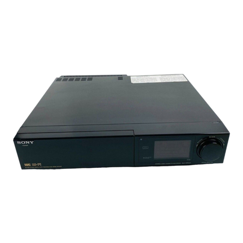
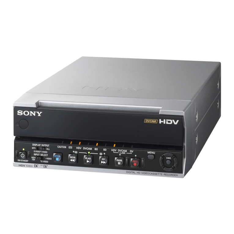
Sony UVW-1800P User manual

Other manuals for UVW-1800P

1

This manual suits for next models

1

Other Sony VCR System manuals

Sony DHR-1000 User manual

Sony

Sony DHR-1000 User manual

Sony DSR-1800A User manual

Sony

Sony DSR-1800A User manual

Sony SLV-N500 - Video Cassette Recorder User guide

Sony

Sony SLV-N500 - Video Cassette Recorder User guide

Sony HVR-1500A User manual

Sony

Sony HVR-1500A User manual

Sony SLV-685HF User manual

Sony

Sony SLV-685HF User manual

Sony SLV-788HF - Video Cassette Recorder User manual

Sony

Sony SLV-788HF - Video Cassette Recorder User manual

Sony SLV-N81 - Hi-Fi VCR User manual

Sony

Sony SLV-N81 - Hi-Fi VCR User manual

Sony SLHF2000 User manual

Sony

Sony SLHF2000 User manual

Sony BETACAM SP BVW-22P User manual

Sony

Sony BETACAM SP BVW-22P User manual

Sony SVO-1330 User manual

Sony

Sony SVO-1330 User manual

Sony POWER TRILOGIC SLV-L49 MX User manual

Sony

Sony POWER TRILOGIC SLV-L49 MX User manual

Sony DVW-250P User manual

Sony

Sony DVW-250P User manual

Sony EV-C100 User manual

Sony

Sony EV-C100 User manual
Sony SLV-585HF User manual

Sony

Sony SLV-585HF User manual

Sony SLV-ED616MJ User manual

Sony

Sony SLV-ED616MJ User manual

Sony DSR-2000 User manual

Sony

Sony DSR-2000 User manual

Sony VCRplus+ SLV-D560P User manual

Sony

Sony VCRplus+ SLV-D560P User manual

Sony SLV-GA59ME User manual

Sony

Sony SLV-GA59ME User manual

Sony HDCAM HDW250 Configuration guide

Sony

Sony HDCAM HDW250 Configuration guide

Sony SLV-EZ70AS/NZ User manual

Sony

Sony SLV-EZ70AS/NZ User manual

Sony SLV-N55 - Video Cassette Recorder User manual

Sony

Sony SLV-N55 - Video Cassette Recorder User manual

Sony SLV-L56AR User manual

Sony

Sony SLV-L56AR User manual
Sony SLV-SE240B User manual

Sony

Sony SLV-SE240B User manual

Sony SRW-5000 User manual

Sony

Sony SRW-5000 User manual

Popular VCR System manuals by other brands

RCA VR678HF user guide

RCA

RCA VR678HF user guide

Zenith VRL4270HF Operating guide & warranty

Zenith

Zenith VRL4270HF Operating guide & warranty

Akai VS-606EA Operator's manual

Akai

Akai VS-606EA Operator's manual

Panasonic NV-SJ412EE operating instructions

Panasonic

Panasonic NV-SJ412EE operating instructions

FUNAI 27C-450 Service manual

FUNAI

FUNAI 27C-450 Service manual

Sanyo VHR-M262EV Service manual

Sanyo

Sanyo VHR-M262EV Service manual

JVC SR-VS20U - Dual Format S-vhs/minidv Recorder instructions

JVC

JVC SR-VS20U - Dual Format S-vhs/minidv Recorder instructions

Grundig GV 7400 EURO Service manual

Grundig

Grundig GV 7400 EURO Service manual

Zenith VCM321 Installation and operating guide

Zenith

Zenith VCM321 Installation and operating guide

JVC HR-A43U, HR-A63U instructions

JVC

JVC HR-A43U, HR-A63U instructions

Aiwa VX-S135U operating instructions

Aiwa

Aiwa VX-S135U operating instructions

RCA VR725HF user guide

RCA

RCA VR725HF user guide

JVC 0703-AH-PJ-BJ instruction manual

JVC

JVC 0703-AH-PJ-BJ instruction manual

TruTech ZV450TT8 owner's manual

TruTech

TruTech ZV450TT8 owner's manual

JVC HR-DVS1EK instructions

JVC

JVC HR-DVS1EK instructions

Sensory Science DDV2120 user guide

Sensory Science

Sensory Science DDV2120 user guide

JVC HR-VP78U instructions

JVC

JVC HR-VP78U instructions

RCA VR611HF user guide

RCA

RCA VR611HF user guide

manuals.online logo
manuals.online logoBrands
  • About & Mission
  • Contact us
  • Privacy Policy
  • Terms and Conditions

Copyright 2025 Manuals.Online. All Rights Reserved.

SONY.
[BETACAM
Ea
VIDEOCASSETTE
RECORDER
UVW-1800P
VIDEOCASSETTE
PLAYER
UVW-1600P
SERVICE
MANUAL
Vol.1
ist
Edition
The
material
contained
in
this
manual
consists
of
information
that
is
the
property
of
Sony
Corporation
and
is
intended
solely
for
use
by
the
purchasers
of
the
equipment
described
in
this
manual.
Sony
Corporation
expressly
prohibits
the
duplication
of
any
portion
of
this
manual
or
the
use
thereot
for
any
purpose
other
than
the
operation
or
maintenance
of
the
equipment
described
in
this
manual
without
the
express
written
permission
of
Sony
Corporation.
Le
matériel
contenu
dans
ce
manuel
consiste
en
informations
qui
sont
la
propriété
de
Sony
Corporation
et
‘sont
destinées
exclusivement
a
!'usage
des
acquéreurs
de
équipement
décrit
dans
ce
manuel.
Sony
Corporation
interdit
formeilement
la
copie
de
quelque
partie
que
ce
soit
de
ce
manue!
ou
son
emploi
pour
tout
autre
but
que
des
opérations
ou
entretiens
de
I'équipement
&
moins
d'une
permission
écrite
de
Sony
Corporation.
Das
in
dieser
Anleitung
enthaltene
Material
besteht
aus
Informationen,
die
Eigentum
der
Sony
Corporation
sind,
und
ausschlieBiich
zum
Gebrauch
durch
den
Kaufer
der
in
dieser
Anieitung
beschriebenen
Ausristung
bestimmt
sind.
Die
Sony
Corporation
untersagt
ausdricklich
die
Vervielfaltigung
jeglicher
Teile
dieser
Anteitung
oder
den
Gebrauch
derselben
fir
irgendeinen
andere
Zweck
ais die
Bedienung
oder
Wartung
der
in
dieser
Anteitung
beschriebenen
Ausristung
ohne
ausdriickliche
schrittliche
Erlaubnis
der
Sony
Corporation.
Introducing
this
manual
Contains
Related
manuals
This
manual
is
the
Service
Manual
Vol.
1
of
the
video
cassette
recorder
model
UVW-1800P
and
the
video
cassette
player
model
UVW-1600P.
This
manual
contains
the
maintenance
information
and
servicing
information
necessary
for
parts
replacement
and
adjustment.
The
sections
covered
in
the
manual
are
summarized
below
to
give
you
a
general
understanding
of
the
manual.
Section
1
OPERATING
INSTRUCTION
Section
2.
INSTALLATION
Section
3.
SERVICE
OVERVIEW
Section
4
MAINTENANCE
MENU
Section
5
PERIODIC
MAINTENANCE
AND
INSPECTION
Section
6
REPLACEMENT
OF
MECHANICAL
PARTS
Section
7
TAPE
PATH
ALIGNMENT
Section
8
ELECTRICAL
ALIGNMENT
OVERVIEW
Section
9
POWER
SUPPLY
AND
SYSTEM
CONTROL
ALIGNMENT
Section
10
SERVO
ALIGNMENT
Section
11
AUDIO
/
TIMECODE
ALIGNMENT
Section
12
VIDEO
ALIGNMENT
~
Section
13.
ELECTRICAL
ALIGNMENT
AFTER
REPLACEMENT
BOARDS
In
addition
to
this
Service
Manual
Vol.
1,
the
following
manuals
are
provided.
*
Operation
Manual
(Supplied
with
equipment)
Explains
how
to
operate
this
equipment.
+
Installation
Manual
(Not
supplied
with
equipment)
Contains
rack
mount
information
necessary
for
installation
of
the
equipment,
the
connector
information
necessary
for
connecting
the
unit
with
peripherals
and
others.
+
Service
Manual
Vol.
2
(Not
supplied
with
equipment)
Contains
the
block
diagrams,
board
tayouts,
schematic
diagrams,
parts
lists.
TABLE
OF
CONTENTS
1.
OPERATING
INSTRUCTION
2.
INSTALLATION
2-1,
Installation
Procedure
.....
2-2.
Operational
Environment.
2-3,
Operating
Voltage......
2-4,
Installation
Space...
2-5.
Supplied
Accessories
..
2-6.
Optional
Accessories
..
2-7.
Rack
Mounting
...
2-8.
Matching
Connectors......
2-9.
Input/Output
Signals
of
the
Connectors
2-10.
Installation
Setup
and
Adjustment
..
on
2-10-1,
Switch
Settings
on
the
Connector
Panel
and
Sub
Control
Panel
-10
2-10-2,
On-board
Switch
Setting
11
2-10-3.
When
Connecting
an
Editor
Controlier
..
2-10-4,
Precautions
After
Installation
..
3.
SERVICE
OVERVIEW
3-1.
3-2.
3-2-1.
3-2-2.
3-2-3,
3-2-4,
3-3,
3-4,
3-4-3,
3-4-2.
3-5.
3-6.
3-7.
3-8.
3-9.
3-10.
3-11.
3-11-1,
3-11-2.
3-11-3.
3-114.
Function
Comparison.
Main
Parts
Location
Location
of
the
Printed
Circuit
Board
.....
Location
of
the
Main
Mechanical
Parts/
Components
....
Location
of
the
Sensor
(1
Location
of
the
Sensor
(2)
Cassette
Compartment
....
Function
of
the
Cassette
Plug
and
Tab
Error
Message
Alarm
..
Enror
Codk
Printed
Circuit
Board
..
Removal
of
the
Cabinet
..
Removal/installation
of
Cassette
Compartment
Removal
of
the
Switching
Regulator.
Replacement
of
Fuse
......
Extension
Board
Replacement
of
the
Boards
CP-225
Board.
CP-226
Board
..
CP-237
Board
..
DR-214
Board
3-11-5.
HP-61
Board
3-36
3-11-6.
KY-249
Board
3-37
3-11-7..
MB-470
Board
3-38
3-11-8.
MB-471
Board
3-40
3-11-9.
MS-39
Board...
3-11-10.
VR-155
Board
.....
3-11-11.
Removal
of
the
Card
Board.
3-11-12,
SOPS-1046
(AC)
Board,
SOPS-
1046
(220
V)
Board
(Inside
the
Switching
Regulator)
...
Take
out
the
Cassette
Tape
in
Slacking
(Manual
Mode)
.....<
Cleaning
when
Heads
are
Clogged
3-14,
How
to
Operate
the
Unit
without
Cassette
Tape.
3-15.
Note
on
Repair
Parts
...
3-15-1,
Notes
on
Repair
Parts...
3-15-2.
Replacement
Procedure
for
Chip
Parts
..
3-15-3.
Replacement
of
Flexible
Card
Wires
3-16.
Fixtures
and
Equipments.
3-16-1.
Fixtures.
3-16-2.
Required
Equipment
3-12,
3-13.
4,
MAINTENANCE
MENU
4-1,
Operation
...
4-2,
Menu
Data
Control
43.
Edit
Check
..
44,
Servo
Check
45.
Servo
Adjust
...
4-6.
—
Service
Suppor
47.
Others.
5.
PERIODIC
MAINTENANCE
AND
INSPECTION
5-1.
Hours
Meter
5-1-1.
Hours
Meter
Display
5-1-2.
Hours
Meter
Reset
..
5-2.
Maintenance
after
Servicing
Unit..
5-2-1.
Video
Head
Cleaning
.....
5-2-2.
Stationary
Head
Cleaning
5-2-3.
Tape
Contacting
Surface
Cleaning.
5-2-4,
Cassette
Up
Compartment
Entrance
Cleanin;
5-3.
Periodic
Inspection
Table
5-3-1.
Maintenance
Item
Configuration
Figure
...
6.
REPLACEMENT
OF
MECHANICAL
PARTS
6-1.
General
Information
for
Parts
Reptacement/
Adjustment...
6-1-1.
Preparation
Before
Parts
Replacement
6-1-2,
Replacement
Parts
Index...
6-2.
Upper
Drum
Replacement
.
6-2-1,
Upper
Drum
Eccentricity
Adjustment
..
6-3.
Drum
Assembly
Replacement
...
6-4,
Drum
Shaft
Grounding
Assembly
Replacement
6-5.
Reel
Table
Assembly
Replacement...
6-5-1.
Ree!
Cover
Removal
...
6-5-2,
Reel
Table
Height
Check/Adjustment
.
6-6.
Reel
Rotation
Detecting
Element
Replacement
..
6-7.
Reel Disc
Replacement...
6-8,
RS
Table
Assembly
Replacement
.......
6-8-1,
Cassette
Support
Stud
(S)
Height
Check/
Adjustment
....
6-9.
Reel
Motor
Replacement
...
6-9-1,
Reel
Motor
Shaft
Vertical
Adjustment
6-10,
Reel
Position
Motor
Repiacement
6-11.
Worm
Gear
Replacement
(Reel
Position
Motor)
6-12,
Reel
Position
Detector
Element
Replacement
6-13.
Brake
Lining
Assembly
Replacement
......
6-13-1,
Reel
Brake
Clearance
Check
..
6-13-2.
Reel
Brake
Releasing
Check
.
6-14,
Brake
Solenoid
Replacement...
6-15.
Pinch
Roller
Arm
Assembly
Replacement
6-16,
Pinch
Press
Assembly
Replacement
.
6-17.
Pinch
Solenoid
Replacement
..
6-17-1.
Pinch
Press
Assembly
Position
Adjustment.
6-18.
Gear
Box
Motor
Replacement...
6-18-1.
Gear
Box
Assembly
Position
Adjustment
6-19.
Worm
Gear
Replacement
(Gear
Box)
6-20.
Gear
Box
Motor
Rotation
Detect
Element
Replacement
....
6-21.
Capstan
Motor
Replacement
..
6-22.
CTL
Head
Replacement
..
6-23,
FE
Head
Assembly/Tape
Cleaner
Assembly
Replacement
.....
6-24,
Audio/Timecode
Head
Replacement
6-25.
AT
Cleaner
Replacement...
6-26.
Cleaning
Roller
Replacement...
6-27.
Replacement
of
Cleaning
Drive
Arm
Roller
6-28.
Replacement
of
Ring
Position
Detector
Element
6-29.
Ring
Roller
Replacement...
6-30.
Tape
Threading
Guide
Replacement
6-31.
Replacement
of
Tape
Threading
Guide
Upper
Flange
....
6-13
6-13
6-32,
Guide
Roller
Assembly
Replacement
6-33.
Loading
Ring
Assembly
Replacement
.
6-33-1.
Position
Adjustment
of
the
Adjusting
Ring
Roiler/Position
Adjustment
of
the
Gear
Box
Assembly
...
6-34,
Tension
Regulator
Arm
Upper
Flange
Replacement
6-35.
Tension
Regulator
Roller
Assembly
Replacement
6-36.
Tension
Regulator
Assembly
Replacement...
6-36-1.
TR
Arm
Return
Position
Adjustment
6-36-2.
FWD/REV
Back
Tension
Adjustment
6-37.
Tension
Sensor
and
DME
Replacement
6-37-1.
Tension
Sensor
Magnet
Position
Adjustment
..
6-38.
Tension
Regulator
Retum
Arm
Replacement
..
6-38-1.
Tension
Sensor
Hook
Position
Adjustment.
.......
6-84
7.
TAPE
PATH
ALIGNMENT
7-1.
Generai
Information
for
Tape
Path
Adjustment
...
7-2.
Tape
Path
Alignment
7-3.
Tape
Path
Check
..
7-4.
Tape
Path
(Entrance
Side)
Adjustment
7-5.
Tape
Path
(Exit
Side)
Adjustment...
7-6.
CTL
Head
Height
Check/Adjustment
7-7.
CTL
Head
Position
Check/Adjusument
7-8.
Audio/Timecode
Head
Height
Check/Adjustment
7-9.
Audio/Timecode
Head
Phase
Check/Adjustment
7-10,
Audio/Timecode
Head-to-tape
CONTACT
Check/
Adjustment...
we
lecwaton
sssaaranses
FAS
7-11.
Audio/Timecode
Head
Position
Check/Adjustment...
7-16
7-12,
REV
Tape
Path
Check/Adjustment
wove
TT
7-13.
RF
Switching
Position
Adjustment
7-14.
Picture
Splicing
Compensation
Adjustment
....
8.
ELECTRICAL
ALIGNMENT
OVERVIEW
8-1.
Adjustment
Component
Index...
8-2.
Required
Equipment
83.
Test
Signal
....
84,
Maintenance
Menu
..
9.
POWER
SUPPLY
AND
SYSTEM
CONTROL
ALIGNMENT
9-1.
Switching
Regulator
Voltage
Adjustment
(+5
V)
9-2,
Switching
Regulator
Voltage
Check
.....
9-3,
Character
Position
Adjustment
...
10.
SERVO
ALIGNMENT
11,
AUDIO/TIME
CODE
SYSTEM
ALIGNMENT
UVW-1600P
11-1.
PB
Mode
Adjustment
..
11-1-1.
PB
Dolby
off
Frequency
Response
Adjustment
1-1-2.
PB
Level
Adjustment
..
1-1-3.
Audio
Meter
Adjustment
UVW-1800P-
11-1,
PB
Mode
Adjustment
1l-1-1.
PB
Dolby
off
Frequency
Response
Adjustment
...
1-1-2,
PB
Level
Adjustment
11-2,
EE
Mode
Adjustment
...
11-2-1.
EE
Input
Level/Audio
Meter
Adjustment
..
11-2-2.
EE
Output
Level
Adjustment
..
1-3.
REC
Mode
Adjustment
...
11-3-1.
Bias
Trap
Adjusument
.
11-3-2.
Bias
Current
Adjustment.
11-4,
Overall
Adjustment
...sssseseseee
11-4-1,
Overall
Level
Adjustment
o.oo
11-4-2,
Overall
Frequency
Response
Adjustment
(Dolby
on)
....
11-5.
Insert
Cross
Talk
Adjustment
....,
4-5-1.
TC
Insert
Crosstalk
Adjustment
.....sssvsseseeeee:
11216
11-5-2.
Audio
CH-i
Insert
Crosstalk
Adjustment
11-17
11-5-3,
Audio
CH-2
Insert
Crosstalk
Adjustment
11-17
11-6.
Erase
Adjustment.
esos
11-18
11-6-1,
AU/TC
Erase
Tune
Adjustment
11-14
12.
VIDEO
SYSTEM
ALIGNMENT
12-1.
VP
Board
(RF,
DM
System)
Adjustment......
12-1-1.
Y
PB
RF
Level
Adjustment
.
CPB
RF
Level
Adjustment
Y
and
C
Demodulator
Adjustment...
.
PB
Y
Frequency
Response
Adjustment
12-1-5.
PB
C
Frequency
Response
Adjustment
12-2,
TBC
Board
Adjustment
..
12-2-1.
INT
SC
Frequency
Adjustment
..
12-2-2,
HCK
Adjustment...
12-2-3,.
Y¥
and
C
Normal
VCO
Adjustment
12-2-4.
Y
and
C
WCK
Frequency
Adjustment.
12-2-5.
Y
and
C
TBC
Input
Level
Check
..
12-2-6.
Y
TBC
Output
and
Gain
Adjustment
12-2-7.
C
TBC
Output
and
Gain
Adjustment
12-2-8.
U-V
Axis
Phase
(B-Y,
R-Y
Phase)
Adjustment
...
12-2-9.
SCH
Phase
Adjustment
..
12-2-10.
Reference
CF
Phase
Adjustment...
12-3.
VP
Board
(VO,
EN)
Adjustmert....
we
12-34
12-3-1.
Component
2
and
1
Y
OUT
Level
Adjustment
..
12-34
12-3-2.
Component
2
and
1
R-Y
OUT
Level
Adjustment
.....
12-3-3.
Component
2
and
1
B-Y
OUT
Level
Adjustment
.....
12-3-4.
Video
Out
1
Y
Level
Adjustment
12-3-5.
Video
Out
2
Y
Level
Adjustment
12-3-6.
Video
Out
1
ENC
SC
Leak
Adjustment
12-3-7,
Video
Out
1
C
Level
Adjustment...
12-3-8.
Video
Out
Burst
Level
Adjustment
....
12-3-9.
Video
Out
2
C
Level
and
Burst
Level
Check
12-3-10.
S-VIDEO
OUT
Y
Level
Adjustment...
12-3-11,
PB
S-VIDEO
C
Level
Adjustment
12-4,
PB
Video
Phase,
Y/C
Delay
Adjustment
(VP-43
Board,
TBC-25
Board)
12-4-1.
PB
Video
Phase
Adjustment
12-4-2,
PB
Composite
Y/C
Delay
Adjustment.
12-4-3.
PB
Component
Y/C
Delay
Adjustment
12-5.
WRA
Board
Adjustment
........
12-5-1.
Component
H
Lock
Loop
12-5-2.
Composite
4
Fsc
Lock
Loop
DC
Adjustment
12-5-3.
Component
Y
Level
Adjustment
12-5-4.
Component
A/D
R-Y,
B-Y
Level
Adjustment
12-5-5.
Component
D/A
R-Y,
B-Y¥
Level
Adjustment.
12-5-6.
Composite
A/D
Level
Adjustment...
12-5-7,
Composite
D/A
Y
Level
Adjustment
12-5-8.
Composite
D/A.
C
Level
Adjustment
12-5.9.
$-VIDEO
Y
Level
Adjustment
«0.00000
12-5-10,
Y
REF
SYNC
Timing
and
Pulse
Width
Adjustment
.......
12-5-11.
Composite
SCH
Detect
Circuit
Adjustment
12-5-12.
Y
Deviation
Adjustment
....
12-5-13.
C
Deviation
Adjusnment
12-6.
RP
Board
Adjustment
..
12-6-1,
Y
REC
Current
Adjustment
12-6-2.
C
REC
Current
Adjustment
12-7,
Overall
Check
and
Adjustment
12-7-1.
Component
Y
and
C
Overall
Frequency
Response
Check
...
12-7-2.
Overall
Component
Y
Level
Adjustment
.....
12-7-3.
Overall
Component
R-Y/B-Y
Level
Adjustment
...
12-7-4,
Overall
Composite
Y
Level
Adjustment
12-7-5.
Overall
Composite
C
Level
Adjustment
12-7-6.
Overall
Video
Phase
Adjustment
..
12-7-7.
Overall
Component
¥/C
Delay
Adjustment
12-7-8.
Overall
Composite
Y/C
Delay
12-7-9.
Overall
S-VIDEO
Y/C
Delay
Adjustment
+
12-35,
13.
ELECTRICAL
ALIGNMENT
AFTER
REPLACEMENT
BOARDS
UVW-1600P
AP-31A
Board
4
PB
Mode
Adjustment
1-1.
PB
Dolby
off
Frequency
Response
Adjustment
1-2.
PB
Level
Adjustment
....
1-3,
Audio
Meter
Adjustment
UVW-1800P
AP-31
Board
AF
2.
PB
Mode
Adjustment
1-1.
PB
Dolby
off
Frequency
Response
Adjustment
1-2.
PB
Level
Adjustment
EE
Mode
Adjustment
..
2-1,
EE
Input
Level/Audio
Meter
Adjustment
2-2.
BE
Output
Level
Adjustment
....
AR-14
Board
3.
4,
5.
6.
REC
Mode
Adjustment
...
3-1,
Bias
Trap
Adjustment
3-2.
Bias
Current
Adjustment
AU/TC
Erase
Tune
Adjustment
..
Overall
Adjustment...
5-1,
Overall
Level
Adjustment
5-2.
Overall
Frequency
Response
Adjustment
(@olby
on)
..
Insert
Crosstalk
Adjustment
....
6-1.
TC
Insert
Crosstalk
Adjustment
6-2.
Audio
CH-1
Insert
Crosstalk
Adjustment
6-3.
Audio
CH-2
Insert
Crosstalk
Adjustment
RP-70 Board
4.
TB
SR
Bs
oes
Component
Y
and
C
Overall
Frequency
Response
Check
Component
Y
and
C
Overall
Over
Modulation
Check
3-31
Y
REC
Current
Adjustment
13-32
CREC
Current
Adjustment
nese
13-36,
C-25
Board
PB
Component
¥
Level
Adjustmen
3-40
PB
Component
B-Y
Level
Adjustment
..
13-40
PB
Component
R-Y
Level
Adjustment
13-41
U-¥
Axis
Phase
(B-Y,
R-Y
Phase)
Adjustment
3-42
PB
Video
Phase
Adjustment...
PB-Composite
Y/C
Delay
Adjustment
INT
SCH
Phase
Adjustment
....
‘VP-43
Board
1,
PB
Component
Y
Frequency
Response
Adjustment
.......
13-49
2.
PB
Component
C
Frequency
Response
Adjustment
.......
13-50
3.
PB
Componeat
Y
Level
Adjustment
<TBC-25
Board>
4.
PB
Component
B-Y
Level
Adjustment
<TBC-25
Board>
5.
PB
Component
R-Y
Leve!
Adjustment
<TBC-25
Board>
6.
U-V
Axis
Phase
(B-Y,
R-Y
Phase)
Adjustment
<TBC-25
Board>
7.
PB
Composite
SC
Leak
Adjustment
8.
PB
Composite
C
Level
Adjustment
9.
PB
Composite
Burst
Level
Adjustment..
}.
PB
S-VIDEO
C
Adjustment
...
.
PB
Composite
Y/C
Delay
Adjustment
<TBC-25
Board>.....
12.
PB
Component
Y/C
Delay
Adjustment
VRA-S5
Board
Overall
Component
Y
Level
Adjustment
Overall
Component
R-Y/B-Y
Level
Adjustment
Overall
Composite
Y
Level
Adjustment
Overall
Composite
C
Level
Adjustment
Overall
Video
Phase
Adjustment.
Overall
Component
Y/C
Delay
Adjustment
Overall
Composite
Y/C
Delay
Adjustment
Overall
S-VIDEO
Y/C
Delay
Adjustment
SS-53
Board
i,
System
ID
Switching
Setting...
2.
Character
Position
Adjustment
er
aweenyr
Volume-2
14,
BLOCK
DIAGRAMS
15.
BOARD
LAYOUTS
16.
SCHEMATIC
DIAGRAMS
17.
SEMICONDUCTOR
PIN
ASSIGNMENTS
18.
SPARE
PARTS
AND
OPTIONAL
FIXTURES
This
section
is
extracted
from
operation
manual.
SECTION
1
OPERATING
INSTRUCTION
xapuy
~
woyeayfoadg
“
ye
Bupooys-a{qnoss,
-
saBuSSaTA!
MIU
Y
uur
pray
+
alayN
SIMO]
OUELA
NUBIA
PUB
SxDIy>)
1epnTayY
wopesuapu0D
ORIN
sSOUTCIT-
HES
aauanbag
womesadg,
‘tp
a8ury
0}
pasp,
suonng
NyeKIdG,
WUaTY
suaaiog
nus
‘among
yeaqyouesa
woneziedig
nuayy
sue)
lias
(2)
L]
ssw
g-gn
soyesauan
apoy
au,
HUSA
06
WIAA
LoyeI9UIH
apo:
aun,
TBUsayLY
ap
BujZ]UOAyoUAS
SHEL
Jasyy
pte
apOD
aUNL,
JeMpnysu0']
40;
sBay9g
ByBG
OULL,
Bye
owpy,
Surdepdsyql
g
sejdeyo
syuaunsn{py
aseyg
Gunipa
gaaydeyg
oyyeuLOTUY
xa,
pasodinjasdng
*
wonneiadg
Suips009y
+
durpuoaay{
£05
worresedaig
uopesad(y
Sujpsoray,
vonwiadg
yorqheya
yougheid
[dg
f0j
uonwmedary
pue
Buypye:
*
wonssadG
ypuqiery
paeydeyo
sywudys
oap],
vauarezoy,
*
won
suns
qq}
pIosay
suojyesedaig
"
asf)
o20j}2g,
eg
so}dey
eoueusIuyeW
S}OUOD
pue
Subd
gaerdey
@san
[oUBg
Tey
40
uoNeoyNUEp)
@v
(ueg
Woy
zsaydeyo
Ma}h0AQ
Dee
*
Sau
ywO
paeydeyo
snueyy
Laaideyo
een
woyanpospiy
syuayu0g
s]ua}u09
1-1
{2)
€]
vors00na
““ayesedo
you
op
suoNg
yodsuers
ade}
out
Ht
“day
4
YstAs
NOK
YORE
[euszeut
pepsooar
Jo
sso}
oweapeur
wedeid
04
azayBa}
SIU
O6f)
“pIODaL
0}
a1q1ssod
you
1
paysnd
$1
anassea
au
uo
nid
ayqHyUt-psod91
oy)
LOY
uoNoBjo1d
piodss
SyosseD
‘sonnow
aq)
to
seadde
you
ose
‘Suyprooas
[ym
Auo
YOU
*Xpoaxiog
196
you
Joudys
rndlur
ay)
yng
‘2;q}ssod
09
100
SOYSHAS
OS9HN
FT
yp
0%
faued
seas
ay
YO
YorMas
UoNIDa}as
Jor2suUO9
indy}
jeUsEs
uaUOduIOD
‘ayt
29s
pur
‘wo}sod
,.°Y-A,
non
eed
uy
“yoduy
[oud
Jona
AseypIsqns
ay1
UO
YONMS
NE
OACIA
ot
wy
wenods
*Butpaosay
10,1
uOnse}es
adAy
jeUB}s
OapyA
ynduy
“Buyprovar
2alj-uomso[sip
aunsita
pu
‘Apoanos
aywiado
0
(91)
soIaL09
aseq
UND
‘ayp
2[quue
[}l/a
STUY,
“2012200
LNANI
OAGIA
“AAU
2p
01
‘peposaa
aq
oy
peuais
a
04
pozittomjauAs
“yeut8ts
oapra
aysodioo
w
wndur
‘azogauong
‘sKeMry
wus
copa
oowazajas
jewarxe
ue
apten
paresado
aq
o1
pouBisap
st
mun
Sy,
iduj
oapa
soualaay
“rey
siayod
epoch
pede
Aureus
ey
Jo
as
ysayy
aqp
aL
Of,
‘9yp
B10U
“HAN
SHI
30
sat
a
1
ri
uononpoujuy
|
-woneiodio3,
‘Sursus
nEIoge]
Aqlog
woys
asua21f
-vometodio9,
7
sansore10qry
Kqj0q
Jo
{epi
parmeznueur
wiaiss
uononpal
asiou
£qjoq,
syemrapen
are
On
ds
C1-a[qnop
ay
pue
£qjoqy
‘oSaied
(1
-youg
8uXejd
10
Suypiosas
uayss
Sunerado
sKumye
are
stnoira
asatys,
“UraysKs
gS
Weoeiag
[euCNUaAUOD
O-Aqlog
owes
ay
asn
z
pure
|
8X20}
orpne
eUIprytSUOT
uaRSNpe,
esjou
oypny
-ssaaaa
adv)
ayeinaoe
pu
yoinb
Buyjquua
‘sjoor
pue
weysdea
‘tunup
2yp
30}
2AUp
19931p
aptaoud
sioj0u
qq
patjonuod-1osssz01do19NU
Anos{
weyshs
ones
sossa00idos01Ny
(Oa)
101981109
aseq
oui
UL-WINg
voddey
&
cody
{8119
1980
30
3477)
Sapoo
ure
pwos
O1
Ran
a4
SmojLe
S9pE—R
poo
ou
4
AY,
“sIwURIS
OIpAe
pur
o9
F98n
40
9,177)
Sap09
BUM
prod9H
0}
Hun
a4
SAO]}e
20yesUeB
apoo
own
tI
jopwaL
PUL
Jo}819UEB
opo?
oUNl
sSuonoun;
yoRqAyid
pue
Buypiooes
yo
oBues
[ny
-Atywoqrewarne
PRod}9p
St
azIS
SHassKA
ANT,
“AOOSI/ONSI-ALAN
U1
UO
y9eq
pated
9q
WUD
SYLA
dS
wUsHI0g
1o4N0
Uo
papiosau
sayasseD
ado)
[erOM
“UY
“NALA
dS
WEIHOG
22(0
LO
eq
padwd
aq
os]e
UED
HUN
sn
UO
PapJOsaI
anesseo
ade)
peau
Y
ULA
dS
weoBeR
JayIO
YM
Ayriquedwiog
‘oapta
sati9g
saptaoud
yeultoy
gg
weorag
ewo)
jevonMaAuod
w
as
pamden0:)
80/18[s0}0
e849
OPE
puE
CAPA
1U91139x3
Jeuud}
dS
wese|eg
“wa1sis
Supipa
We
u]
Japtonas
ay)
se
pasn
aq
ueD
Hun
olp
pue
“2;qe[0
ame
suonsuny
spinys
poe
Sof
‘paroouuos
jun
jorTUGD
FeUTALXS
Ue
qILA
“s]eUBES
orpne
Soyzuy
pure
oapta
ianodwzoa
‘oapsa
ayjsnduino
youg
BuiXeyd
pee
dupa0oas
30
a1qedea
‘sopzooaa
ayassuaoapes
gg
umeavIeg
¥
St
{OOSL/OORI-AVAN
UL
seinjee,
DET
*
SaanyeaT
“d0081/0081-M.
AN
9tp
Jo
saaniea)
ami
saroqarono
rdeyp
sia,
MOIIAIZAQ
|
Jaydeyo
1-3