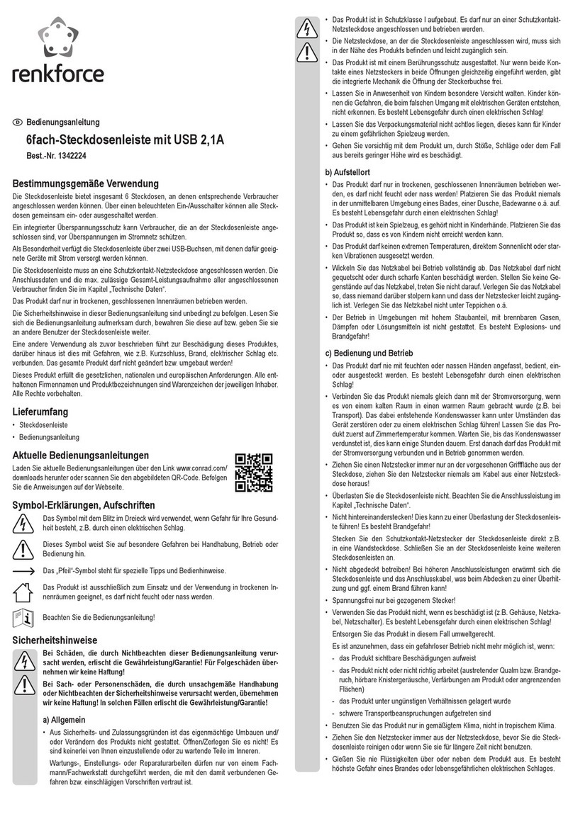
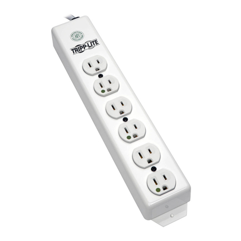
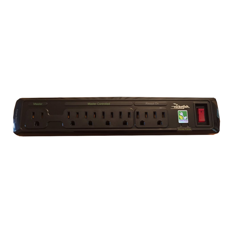
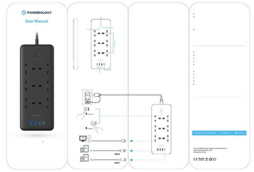
Sophisticated Circuits PowerKey Pro 200 User manual

1: Introduction Page 1
PowerKey Pro
Model 200
User Manual
by Jamie Green
PowerKey Pro designed by Amar Singh
PowerKey Software by Richard Elmore
User Interface and Graphics by Jamie Green
Balloon Help by Beverlee Heiszler
Moral Support by Alora Dunlap
Copyright ©1995-97 Sophisticated Circuits, Inc. All rights reserved.
MANPKP2-1097

Page 2 1: Introduction
IMPORTANT SAFETY INSTRUCTIONS
When using your telephone equipment, basic safety precautions should always be followed to reduce the risk of fire,
electric shock and injury to persons, including the following:
1. Read and understand all instructions.
2. Follow all warnings and instructions marked on the product.
3. Unplug this product from the wall outlet before cleaning.
4. Do not allow anything to rest on the power cord. Do not locate this product where the cord will be abused by persons
walking on it.
5. Do not overload wall outlets and extension cords, as this can result in the risk of fire or electric shock.
6. Unplug this product and refer servicing to qualified service personnel under the following conditions: when the
power supply cord or plug is damaged or frayed, if liquid has been spilled into the product, if the product has been
exposed to rain or water, or if the product has been dropped or damaged.
SAVE THESE INSTRUCTIONS
FCC Requirements
1. The Federal Communication Commission (FCC) has established Rules which permit this device to be directly
connected to the telephone network. Standardized jacks are used for these connections. This equipment should not be
used on party lines or coin phones.
2. If this device is malfunctioning, it may also be causing harm to the telephone network; this device should be
disconnected until the source of the problem can be determined and until repair has been made. If this is not done, the
telephone company may temporarily disconnect service.
3. The telephone company may make changes in its technical operations and procedures; if such changes affect the
compatibility or use of this device, the telephone company is required to give adequate notice of the changes. You will be
advised of your right to file a complaint with the FCC.
4. If the telephone company requests information on what equipment is connected to their lines, inform them of:
a. The telephone number to which this unit is connected.
b. The ringer equivalence number.
c. The USOC jack required.
d. The FCC Registration Number.
Items (b) and (d) are indicated on the label. The Ringer Equivalence Number (REN) is used to determine how many devices
can be connected to your telephone line. In most areas, the sum of the REN’s of all devices on any one line should not
exceed five (5.0). If too many devices are attached, they may not ring properly.
Service Requirements
In the event of equipment malfunction, all repairs should be performed by our Company or an authorized agent. It is the
responsibility of users requiring service to report the need for service to our Company or to one of our authorized agents.
Service can be obtained at Sophisticated Circuits, Inc., 19017 120th Ave NE, Suite 106, Bothell, WA 98011, 206-485-7979.
FCC Statement
This equipment has been tested and found to comply with the limits for a Class B digital device, pursuant to Part 15 of the
FCC Rules. These limits are designed to provide reasonable protection against harmful interference in a residential
installation. This equipment generates, uses and can radiate radio frequency energy and, if not installed and used in
accordance with the instructions, may cause harmful interference to radio communications. However, there is no
guarantee that interference will not occur in a particular installation. If this equipment does cause harmful interference to
radio or television reception, which can be determined by turning the equipment off and on, the user is encouraged to try
to correct the interference by one or more of the following measures:
• Reorient or relocate the receiving antenna.
• Increase the separation between the equipment and receiver.
• Connect the equipment into an outlet on a circuit different from that to which the receiver is connected.
• Consult the dealer or an experienced radio/TV technician for help.
Shielded cables and I/O cords must be used for this equipment to comply with the relevant FCC regulations.
Changes or modifications not expressly approved in writing by Sophisticated Circuits, Inc. may void the user’s authority to
operate this equipment.
Industry Canada Equipment Attachment Limitations
NOTICE: The Canadian Industry Canada label identifies certified equipment. This certification means that the equipment
meets certain telecommunications network protective, operational and safety requirements. The Department does not
guarantee the equipment will operate to the user’s satisfaction.
Before installing this equipment, users should ensure that the equipment meets certain telecommunications network
protective, operational and safety requirements. The Department does not guarantee the equipment will operate to the
user’s satisfaction.

1: Introduction Page 3
Before installing this equipment, users should ensure that it is permissible to be connected to the facilities of the local
telecommunications company. The equipment must also be installed using an acceptable method of connection. In some
cases, the company’s inside wiring associated with a single line individual service may be extended by means of a
certified connector assembly (telephone extension cord). The customer should be aware that compliance with the above
conditions may not prevent degradation of service in some situations.
Repairs to the certified equipment should be made by an authorized Canadian maintenance facility designated by the
supplier. Any repairs or alterations made by the user to this equipment, or equipment malfunctions, may give the
telecommunications company cause to request the user to disconnect the equipment.
Users should ensure for their own protection that the electrical ground connections of the power utility, telephone lines
and internal metallic water pipe system, if present, are connected together. This precaution may be particularly important
in rural areas.
Caution: Users should not attempt to make such connections themselves, but should contact the appropriate electric
inspection authority, or electrician, as appropriate.
The Load Number (LN) assigned to each terminal device denotes the percentage of the total load to be connected to a
telephone loop which is used by the device, to prevent overloading. The termination on a loop may consist of any
combination of devices subject only to the requirement that the Load Numbers of all the devices does not exceed 100.
The Load Number of this unit is 6.
Copyright Notice
The PowerKey Pro manual, program, product design and design concepts are copyrighted, with all rights reserved to
Sophisticated Circuits, Inc. Your rights are subject to the copyright laws of the United States of America. Under the
copyright laws, this manual may not be copied, in whole or part, including translation to another language or format,
without the express written consent of Sophisticated Circuits, Inc.
Trademarks
PowerKey and PowerPad are registered trademarks of Sophisticated Circuits, Inc.
Apple, AppleScript, Macintosh, Mac, PowerBook and Power Macintosh are registered trademarks, and Balloon Help,
Finder and System 7 are trademarks of Apple Computer, Inc.
PowerPC is a trademark of International Business Machines Corporation.
Frontier is a trademark of UserLand Software, Inc.
QuicKeys is a trademark of CE Software, Inc.

Page 4 1: Introduction
Contents
Introduction 7
System Requirements 8
What’s in the Box 8
Using This Manual 9
Installing PowerKey Pro 11
Hardware Installation 12
Preparing for Installation 13
Connecting the Power Cords 14
Connecting the ADB Cables 16
Connecting the Phone Cables 18
Turning On Your System 19
Software Installation 20
Hardware Configuration 21
Using PowerKey Pro 23
Starting Up the System 24
Shutting Down the System 24
Scheduled Events 25
The PowerKey Schedule 26
Creating an Event 28
A Pair of Hot Key Events 32
A “Monitor Saver” Event 35
A Phone Startup Event 38
Reference 43
Software Components 44
PowerKey Editor 45
Schedule Windows 45
PowerKey Editor Menus 47
File Menu 47
Edit Menu 47
Schedule Menu 48

1: Introduction Page 5
Importing and Exporting 50
Hardware Setup 52
Preferences 54
The Event Editor 55
Event Triggers 58
Time Triggers 58
System Triggers 60
Trigger Qualifiers 64
Event Actions 68
Appendices 77
1. Using “Classic” PowerKey 78
Installing PowerKey 78
2. Using Multiple PowerKeys 80
Installing Multiple PowerKey Pros 80
Installing PowerKey Pro and “Classic” PowerKey 81
Using PowerKey Software with Multiple PowerKeys 82
3. Restarting Crashed Servers 83
Server Restart Option 84
Server Restart Option Features 85
Using the Server Restart Option 88
4. Default Schedules 91
Creating a Default Schedule File 91
Using a Default Schedule File 92
5. Using AppleScript 93
Running AppleScripts in Events 93
Controlling PowerKey Pro with AppleScript 94
6. Troubleshooting 97
7. How To Reach Us 101
Index 102

Page 6 1: Introduction

1: Introduction Page 7
Chapter1
Introduction
Thank you for purchasing PowerKey®Pro!
PowerKey Pro Model 200 is a “smart” power strip that can
control an entire Macintosh®system. You can start up your
computer and all (or just some) of your peripherals with one
keystroke. You can start up your system with a phone call. You
can create schedules to control your system at any time of the
day or night.
The PowerKey Pro unit has six outlets that switch as two
groups, to allow you to control your peripherals indepen-
dently. It offers the security of power surge protection for all
devices connected to it, including your modem and phone.
With the included software, you can turn on your peripherals
with the touch of a key, or automatically turn off your monitor
when the computer is idle. You can set up timed events to
automate many day-to-day tasks, for example to turn on your
computer before you get to work or run nightly unattended
backups. If you purchase our optional Server Restart Option™,
you can even automatically restart your computer when it
crashes!

Page 8 1: Introduction
System Requirements
PowerKey Pro Model 200 works with any desktop Macintosh
or compatible except the original Mac®and Mac Plus (because
they do not have an ADB port). It works with any Apple
keyboard, and most third-party keyboards. Its phone ring
detection feature works with any standard analog phone line
(see Appendix 4, Troubleshooting, for more information on
phone lines).
PowerKey Pro can also work with some models of
PowerBook®computers that have an ADB port. You must use
an external keyboard, our own PowerPad®or a special adapter
cable to start up your system. Contact us for more information.
The PowerKey software requires System 7™ or later, and runs
in native PowerPC®mode on the Power Macintosh. It sup-
ports Balloon Help™, Apple Events and AppleScript®.
What’s in the Box
The PowerKey Pro package includes the following:
• PowerKey Pro Model 200 unit
• SCI cable for connecting PowerKey Pro to your computer
and keyboard
• Phone cable for connecting PowerKey Pro to your tele-
phone line
• Software disk for controlling PowerKey Pro
• This manual
• Postage-paid registration card
If you’re missing any of these items, please notify your sup-
plier.

1: Introduction Page 9
Using This Manual
We recommend that you read this manual as follows:
1. Carefully follow the instructions in Chapter 2, Installing
PowerKey Pro.
2. Skim the first part of Chapter 3, Using PowerKey Pro.
If you want to use PowerKey Pro’s advanced Scheduling
features:
3. Follow along with the Creating an Event tutorial in Chapter
3.
4. Look through the other example Events in Chapter 3 to
find those that will be useful to you.
5. Skim Chapter 4, Reference, to learn the details of the
Scheduling features.
As you read the manual, you will encounter symbols next to
some paragraphs:
This symbol denotes a paragraph that contains important informa-
tion regarding the current topic. Be sure to read these notes carefully.
This symbol denotes a paragraph that contains a handy tip, or an
idea for using a feature.

Page 10 1: Introduction

2: Installing PowerKey Page 11
Chapter2
Installing
PowerKeyPro
PowerKey Pro consists of two primary components, hardware
and software. The hardware unit controls the outlets and
keeps track of time when the computer is turned off. The
software organizes the scheduled events and controls the
outlets when the computer is turned on.
In order to use PowerKey Pro, you must install both the hardware
and software.
Hardware Installation 12
Preparing for Installation 13
Connecting the Power Cords 14
Connecting the ADB Cables 16
Connecting the Phone Cables 18
Turning On Your System 19
Software Installation 20
Hardware Configuration 21

Page 12 2: Installing PowerKey
Hardware Installation
PowerKey Pro Model 200 has six outlets. The outlet labelled
“Always On” is an unswitched convenience outlet. The outlet
labelled “1” switches on and off independently. The rest of the
outlets are labelled “2” and switch as a group.
Always On
This outlet is
unswitched.
Outlet
1
This outlet ca
n
be controlle
d
individuall
y.
Outlet
2
These outlet
s
switch on an
d
off togethe
r.
At the back of PowerKey Pro are two phone ports and a
special “SCI” port.
This is not a “SCSI” port, which is used to connect hard disks to
your Mac. It is a custom port used only by PowerKey Pro. “SCI”
stands for “Sophisticated Circuits, Inc.”
SCI Port
Connects to
the computer
via SCI Cable.
Line Port
Connects to
the phone line.
Phone Por
t
Connects t
o
the telephone
.

2: Installing PowerKey Page 13
Preparing for Installation
Determine your computer’s switch type
With your computer off, press the “Power On” key
(usually found at the top or upper right corner of
your keyboard). If your computer starts up it has Soft
Power, otherwise it has Hard Power. This informa-
tion will be important later when you are connecting your
computer’s power cords to your PowerKey Pro.
If your computer started up in the above test (i.e. it has Soft
Power), shut it down before continuing.
Unplug your system
1. Make sure that all the power switches on your Macintosh
and peripherals are turned off.
2. Disconnect the power cords for your Macintosh and
peripherals from the wall outlet or power strip.
3. Disconnect the keyboard cable from the Apple
Desktop Bus (“ADB”) port on the back of your
computer. The ADB port is labelled with the icon
shown at the right.
4. If you have a modem, unplug the phone cable leading
from the wall to the modem.

Page 14 2: Installing PowerKey
Connecting the Power Cords
1. Plug the power cord for PowerKey Pro into the wall outlet.
Plug in your computer
If you are also installing the Server Restart Option add-on software,
see Appendix 3, Restarting Crashed Servers, before plugging in
your computer.
2. Connect the power cord for your computer as follows:
• If your computer has Soft Power, you should plug it into
the wall or the Always On outlet.
• If your computer has Hard Power, you should plug it into
one of the switched outlets of PowerKey Pro.
Remember which outlet you plug the computer into. You will need to
tell the PowerKey software where the computer is, so it can correctly
start up and shut down the system.
Plug in your peripherals
3. Plug the power cords for your peripherals into the other
outlets of PowerKey Pro, as desired.
In general, you’ll want most of your peripherals to turn on and off
together, so you should plug these into the Outlet 2 group. Outlet 1
is then available for a device which you would like to switch sepa-
rately.
In fact, a good use for Outlet 1 is for the monitor. In Chapter 3 we
will describe a “monitor saver” feature which will turn your monitor
off when your computer is idle.

2: Installing PowerKey Page 15
Example
This example shows PowerKey Pro connected to a Power Mac
6100, a printer and a modem:
The Power Mac 6100 has Hard Power, so it is plugged into
Outlet 2. The modem and printer are also plugged into Outlet
2, so they will all turn on together. The monitor is connected to
Outlet 1, and can be turned on and off separately from the rest
of the system.
A computer with Soft Power would be connected similarly.
The only difference is that the computer would be plugged
into the Always On outlet or directly into the wall.
We designed PowerKey Pro so that there is room between
outlets for many typical “power bricks” such as those used by
modems. If you still don’t have enough room, you can use a
short extension cord. Many computer stores sell very short
cords just for this purpose.
If you plug your monitor into PowerKey Pro instead of your com-
puter, it can be controlled separately. Chapter 3 describes a sample
Event which will turn off your monitor when the computer is idle.

Page 16 2: Installing PowerKey
Connecting the ADB Cables
The diagram below shows an example setup:
(1) SCI Cable. (2) Branching connector.
The cable that comes with PowerKey Pro is not a
standard ADB cable. One end of this cable is colored
purple, and labelled with our company’s logo (as shown
to the right). This connector will only fit into the SCI
Port on the PowerKey unit.
Connect PowerKey Pro to the computer
1. Plug the single end of the SCI Cable (see note 1 in the
diagram above) into the SCI Port on PowerKey Pro.
2. Plug the branching end of the SCI Cable into the ADB port
on the back of your computer.
(1)
(2)

2: Installing PowerKey Page 17
Connect the keyboard to the SCI Cable
3. Plug the keyboard cable into the branching connector on
the SCI Cable (see note 2 in the diagram above). If you
have other ADB devices, they should be connected in a
“chain,” with one end of the chain joining to the branching
connector.
The keyboard must be connected to the branching connector on the
SCI Cable in order for PowerKey Pro to work.

Page 18 2: Installing PowerKey
Connecting the Phone Cables
This section is optional. If you do not wish to use PowerKey Pro’s
phone ring detection feature, you may skip this section.
The diagram below shows an example setup:
Connect PowerKey Pro to the phone line
1. Plug the cable running from your phone outlet
into the Line Port on the back of PowerKey Pro
(labelled with the symbol at the right).
Connect the modem to PowerKey Pro
2. Plug the supplied phone cable into the Phone
Port on the back of PowerKey Pro (labelled with
the symbol at the right), and into the line port on
your modem or phone.
3. If you have both a phone and modem, you can chain them
together as shown in the diagram above.

2: Installing PowerKey Page 19
If you wish to connect multiple devices that don’t have “pass
through” ports, you may use a phone line splitter (available at any
phone or electronics store).
Turning On Your System
1. Turn on the power switches on your computer (if it has
Hard Power) and peripherals.
2. Press the “Power On” key on the keyboard. PowerKey Pro
will turn on its outlets, and your entire system will start
up!
As you can see, the PowerKey Pro hardware can start up the
system. The PowerKey software is required to shut it down.
The next section shows you how to install the software and
configure it for use.

Page 20 2: Installing PowerKey
Software Installation
Open the Installer
1. Insert the PowerKey Pro
disk into your floppy
drive. The disk’s window
will appear.
2. Double-click the icon
labelled “Install Power-
Key.” The Installer window will open.
Install the software
3. Make sure your startup disk is shown in the Destination
Disk panel. If it is not, click the Switch Disk button until it is
shown.
If you are also installing the Server Restart Option, see Appendix 3,
Restarting Crashed Servers, for installation instructions.
4. Click Install. The Installer will ask if it can quit any open
applications before it begins. Make sure you don’t have
any unsaved documents, then click Continue.
When the installation is complete, the Installer will restart
your computer.
Table of contents
Other Sophisticated Circuits Power Strip manuals

