Sorensen X1A 500F User manual

Operator`s Manual
for Sörensen liftgates:
Sörensen Hydraulik GmbH - Osterrade 3 - 21031 Hamburg - Tel +49 (0)40 739 606 0 - www.soerensen.de
X1A 500E
X1A 500F
© Sörensen Hydraulik GmbH
Operator`s Manual for Sörensen liftgates:
X1A 500E, X1A 500F, X1A 600E, X1A 600F
Plus-point product diversity
TECHNOLOGY
X1A 600E
X1A 600F

© Sörensen Hydraulik GmbH
Sörensen Hydraulik GmbH - Osterrade 3 - 21031 Hamburg - Tel +49 (0)40 739 606 0 - www.soerensen.de
Sörensen Hydraulik GmbH
Osterrade 3 - D-21031 Hamburg
phone:
fax:
internet:
e-mail:
+49 (0) 40 / 739 606 0
+49 (0) 40 / 739 606 66
www.soerensen.de
Spare parts:
Sales department:
phone:
fax:
phone:
fax:
e-mail:
+49 (0) 40 / 739 606 68
+49 (0) 40 / 739 606 77
+49 (0) 40 / 739 606 14
+49 (0) 40 / 739 606 69
Plus-point product diversity
Operator`s Manual for Sörensen liftgates:
X1A 500E, X1A 500F, X1A 600E, X1A 600F

Operator`s handbook
20 911 278
1
Model: X1A 500E/F and X1A 600E/F
Version 04.2019
Contents
General................................................................................................................................3
Description of the Sörensen liftgate.....................................................................................3
Electric system/operating unit..............................................................................................3
Foot controls........................................................................................................................4
Priority controlling ................................................................................................................4
Hydraulic..............................................................................................................................4
Main frame...........................................................................................................................4
Platform ...............................................................................................................................4
Daily visual inspections........................................................................................................4
Annual inspection ................................................................................................................4
Battery capacity ...................................................................................................................5
Our recommendation for the battery capacity:.....................................................................5
The electro-motor ................................................................................................................5
Like this you can prevent.....................................................................................................5
Handling and behavior during the operation........................................................................6
Un-allowed is further more:..................................................................................................6
Closing down the liftgate......................................................................................................6
Maintenance........................................................................................................................6
Use ......................................................................................................................................6
General instructions.............................................................................................................7
Allowed load ........................................................................................................................7
Driving loads on to the platform from the vehicle floor.........................................................7
Loading diagram / capacity..................................................................................................8
Danger clue –Sticker “safe handling of the liftgate” ............................................................9
Danger instruction about unsecured load ..........................................................................10
Rolling loads......................................................................................................................10
Description of the safety ....................................................................................................10
Hose break valves .............................................................................................................10
Safety valve.......................................................................................................................10
Electric fuses .....................................................................................................................10
Cart stops ..........................................................................................................................11
Warning markings and flashlights......................................................................................11
Safety instructions for the function.....................................................................................12
Driving on the platform.......................................................................................................12
Securing load.....................................................................................................................12
Transshipping from one vehicle to another........................................................................13
Driving with a fork lift on the platform lying on the ground..................................................14
Turning on the liftgate........................................................................................................14
Control panel .....................................................................................................................15
Controlling the liftgate from the platform............................................................................15
Foot controls......................................................................................................................15
Option handheld remote with spiral cable..........................................................................16
Users manual for the liftgate X1A 500F and X1A 600F .....................................................17
Care, maintenance, inspection and repair .........................................................................21
Hydraulic oil - recommendations........................................................................................21

Operator`s handbook
20 911 278
2
Model: X1A 500E/F and X1A 600E/F
Version 04.2019
Diagnosis diode.................................................................................................................22
Test of the sensor-switch in the platform: ..........................................................................23
Test of the pressure switch S4:..........................................................................................23
Troubleshooting.................................................................................................................24
Operation failure ................................................................................................................26
Warranty............................................................................................................................26
Liability exclusions.............................................................................................................26
This operator`s manual is valid for the following liftgates:
X1A 500E, X1A 500F and X1A 600E, X1A 600F

Operator`s handbook
20 911 278
3
Model: X1A 500E/F and X1A 600E/F
Version 04.2019
General
Read this operator`s manual carefully, before using the liftgate. The hand book shall make
you familiar with the way the liftgate is working, and warn for malpractice. The instructions
contained therein are issued for security reasons, and for better conservation of the
product. The Sörensen - liftgate may only be used for lifting and lowering loads, that must
be placed according to the loading diagram. The lifting ability of the liftgate can be seen in
the loading diagram on page 8.
The liftgate may only be used, maintained and repaired by personal that have an
appropriate briefing about the mechanics of the device, and the dangers connected to the
use of the device. All regulations for prevention of accidents must be complied to. The
essential provisions are printed in the check book of this liftgate. The checkbook is a part
of this operator`s manual.
Is the liftgate is operated by untrained personal, hazards for the operator as well as other
persons can occur. All safety regulations must be complied to.
It is not allowed to make any changes on the liftgate without prior written approval from the
constructing department of Sörensen. Only original spare parts are may be used for repair
of the liftgate. Sörensen is not liable for damages which occur through not compliance with
the prescribed directions in the operator`s manual
The operator`s manual shall therefore be kept in the cabin of the vehicle, so it is possible
to look into it for instruction. The liftgate production number is necessary for ordering spare
parts, to make warranty claims or obtain technical information. You will find the liftgate
production number on the name plate located on the tilt arm. A second nameplate is
located on the inside of the power pack cover. Further more the number is engraved in the
left main mounting flange.
Description of the Sörensen liftgate
You have decided to purchase a liftgate of top quality. Sörensen liftgates comply with the
EG Maschinenrichtlinie 2008/42/EG, as well as DIN EN 1756 –1.
The Sörensen –liftgate is very undemanding. It has maintenance free bushings and must
not be greased throughout its lifetime.
Electric system/operating unit
The controlling of the different functions are done with the very flat control panel page 15.

Operator`s handbook
20 911 278
4
Model: X1A 500E/F and X1A 600E/F
Version 04.2019
Foot controls
With the foot controls located on the platform, the liftgate can be lowered to the ground
and can be lifted to the height of the vehicle floor. The tilt-down and tilt-up at the ground
are automatic.
Priority controlling
The foot control is a priority controlling. Are the liftgate operated with the foot controls then
(the control panel, and the cabled remote) is electrical blocked.
Hydraulic
The liftgate are driven with a power pack unit which are is mounted directly on the tilt
cylinder or on the main frame of the liftgate. With this the liftgate can be driven in any
wanted position over the lift and tilt cylinder. The cylinder rods are nitrated.
Main frame
The main frame as well as the other steel parts are painted black (RAL 9005).
The installation brackets are mounted in the right position for the type of vehicle present.
Every new type of liftgate is driven 80.000 cycles in a long-time test, before given free for
sale.
Platform
The platform is made with aluminum extrusions which are clipped together and welded to
a cross extrusion with the platform tip to obtain high stability.
Daily visual inspections
Function and completeness of the operation- and Safety devices
Readability of control and instruction signs
Damages and completeness of pins and pin locks.
Damages and tightness of hydraulic hoses, fittings valves
On the cylinders
Damages and function of event flashlights
Main switch (special equipment) must be tested for function
Any lack must instantly be fixed, and any missing parts must be replaced!
The operator is responsible for the timely maintenance and repair of detected errors!
The operator`s manual must always be available in the vehicle!
Repairs may only be made with original spare parts!
Annual inspection
After taking the liftgate in use, it must be inspected by an expert at least 1 time in a year.
The results must be notated in the check book of the liftgate.

Operator`s handbook
20 911 278
5
Model: X1A 500E/F and X1A 600E/F
Version 04.2019
Battery capacity
The battery capacity for the use of liftgates are normally prescribed by the vehicle
producer, please always comply to the vehicle manufacturers installation guidelines.
Our recommendation for the battery capacity:
To build in a stronger generator and an extra battery is basically recommended. The user
is responsible for the charging level of the battery.
The electro-motor
The Electro motor of the power pack has depending on capacity an input of 0,8 KW till 3KW.
That gives by full voltage:
12 Volt a current of 150 A. Is the voltage lowered to 9 volt, the current will double to 300 A.
24 Volt a current of 150 A. Is the voltage lowered to 12 volt, the current will double to 300 A.
This high current at low voltage results in excessive-heating of the copper winding.
The result is that the protective lacquer melts, which can lead to a short-circuit and even
a burned motor.
Like this you can prevent
You can avoid damages to the motor and the motor relay, if you always have sufficient
voltage on the battery. If you experience that the motor has problems lifting a load that
normally is no problem, then immediately stop the action and take care that the battery are
charged.
If you realize that the batteries are running out of power too soon, then let an expert
examine the batteries and the cables leading to the power pack. Possibly the cables + and
ground must be changed.
Take care that the charging fazes for the batteries are sufficient between the single
loadings or unloading.
Capacity 500 kg, 600 kg
12 Volt - 1 x 88 Ah
24 Volt –2 x 66 Ah

Operator`s handbook
20 911 278
6
Model: X1A 500E/F and X1A 600E/F
Version 04.2019
Handling and behavior during the operation
(1) Liftgates may not be loaded with a higher load than its allowed max. load. (Always take
care that the loading distance is correct)
(2) Loads shall be placed in a way, that unwanted position changes do not occur.
(3) Entering and leaving the platform must be done over the allowed ways.
(4) Liftgates may only be controlled from the control positions meant be used for
controlling.
(5) The operator must by all movements of the liftgate take care that he/she or other
persons are not at any risk.
(6) Unnecessary stay on or in the range of motion of the platform, are prohibited.
Un-allowed is further more:
1. Stay under the load handling attachments
2. To step on the load handling attachments
3. To be more persons than the operator on the platform by moving.
4. Use of the liftgate for purposes which it is not designed for.
(7) Moving liftgates are only to be driven with, when the platform is in the driving position.
(8) The platform may not be put in movements, which may lead to getting thrown off.
Closing down the liftgate
When power driven liftgates are taken out of use, they shall be secured against un-allowed
use.
Maintenance
(1) Before doing maintenance on elevated parts of the liftgate, these parts must be
secured against unwanted movements.
(2) To prevent a falling down or a sinking down of the platform all bearing elements, power
pack and safety devices as well as the hydraulic connections are to be examined, and
defect parts must be renewed. (3) Hydraulic hoses shall be renewed when necessary –
though latest after 6 years.
The changes of the hydraulic hoses as well as other maintenance made, must be noted in
the check book of the liftgate.
Use
The Sörensen liftgate are designed for lifting and lowering loads. It may only be operated
by one person, and only one person are allowed to drive on the platform.

Operator`s handbook
20 911 278
7
Model: X1A 500E/F and X1A 600E/F
Version 04.2019
General instructions
Attention! When the liftgate are in use, it must be secured that the vehicle does not
make any unwanted movements. The liftgate must be observed during all functions that
can be driven from the control system.
Attention! The complete working area of the liftgate must be kept free of persons or
objects. Special attention shall be given to the squish and shear area between platform
and body, as well the area between the platform and the ground.
Allowed load
Attention! The max. load of the liftgate may not be exceeded. Be aware of the
loading diagram on the name plate. The one side load is 50 % of the max. load of the
liftgate. The load center shall be kept as central as possible between the lifting arms. The
bigger the loading distance is. The lower is the allowed load.
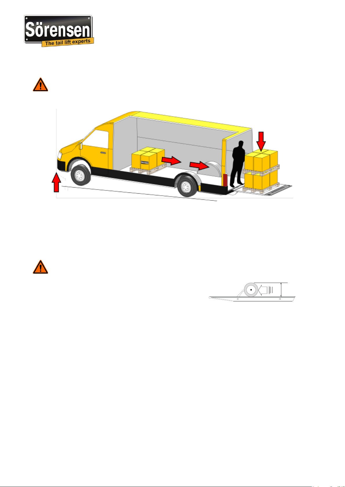
Driving loads on to the platform from the vehicle floor
Attention! Safeguarding against loads that are larger than the max. loads or loads
which is not placed in the correct loading distance and loads driven from the vehicle to the
platform, is impossible. An overload like this can lead to a break of the platform. It is the
operator responsibility that the platform are not loaded with loads, that exceed the allowed
loads in the loading diagram.
Center
Loadcenterdistance

Operator`s handbook
20 911 278
8
Model: X1A 500E/F and X1A 600E/F
Version 04.2019
Loading diagram / capacity
In addition to the operating instructions, the liftgate loading diagram is also shown
on its identification plate.
The load's centre of gravity should be in the middle between the lift arms.
The greater the distance of the load from the end of the flatbed, the lower the loading
capacity.
The maximum loading capacity specified in the loading diagram must not be exceeded.
The platform may not be used as a bridge plate.
Drive only the functions lifting and lowering when the platform is horizontal. The platform
may not be tilted down, when loaded and in elated condition.
Loadcenterdistance

Operator`s handbook
20 911 278
9
Model: X1A 500E/F and X1A 600E/F
Version 04.2019
Danger clue –Sticker “safe handling of the liftgate”
The sticker is delivered with all new liftgates and must be placed on a visible place on the
inside of the rear part of the vehicle. The danger clue –sticker shows possible falls actions
and right actions in the single pictograms.
This sticker can be ordered under the part number 20 909 238.
Operator`s handbook
20 911 278
10
Model: X1A 500E/F and X1A 600E/F
Version 04.2019
Danger instruction about unsecured load
Attention! Under very unfavorable conditions there is by loading and unloading over
a liftgates platform, a risk that the front aches are lifted. The sloping of the vehicle can lead
to movements of not secured loads, which can lead to personal risks.
Rolling loads
Rolling or slippery goods must be secured on the platform. Without cart-stops it is not
allowed to have rolling loads on the platform.
Sörensen liftgates can if wanted be equipped with cart-stops, (wheels with maximum
diameter 110 mm) are safely secured.
Attention! Be aware of the safety instruction about unsecured load, by especially
liftgates without support legs.
Description of the safety
Hose break valves
If a hose bursts, or a tube or a fitting breaks, the liftgate will, according to valid norm, lower
the platform in a controlled way, with the allowed speed, as long as one of the functions on
the controls are activated. Are no function then activated anymore the liftgate will stop
immediately.
Safety valve
The liftgate is limited with a safety valve to lift only the max. permitted load. This valve is
pre-adjusted from the factory, and adjustment of it is only permitted for experts by using a
test weight and a manometer.
Electric fuses
Defect fuses are only to be renewed with fuses that have the values defined in the wiring
diagram, and the on control unit. Larger fuses can lead to cable fire.
Max. 110 mm

Operator`s handbook
20 911 278
11
Model: X1A 500E/F and X1A 600E/F
Version 04.2019
Cart stops
Attention! Are roll-container used, the liftgate must be equipped with cart stops. The
function of the cart stops can be limited by dirt. The operator shall always keep these
safety devices clean.
Warning markings and flashlights
The liftgates platform can be equipped with warning marks and/or with flashlights. These
safety devices must always be functionally and be kept clean.

Operator`s handbook
20 911 278
12
Model: X1A 500E/F and X1A 600E/F
Version 04.2019
Safety instructions for the function
Driving on the platform
Attention! By loading the platform it
must be secured that there are sufficient
room left on the platform so that the
operator can drive along on the platform
and operate the liftgate.
Only the operator are permitted to drive
on the platform.
Securing load
Attention! Make sure
that the load are secured
against slipping and
kipping!
An elevated platform may
not be tilted down.

Operator`s handbook
20 911 278
13
Model: X1A 500E/F and X1A 600E/F
Version 04.2019
Transshipping from one vehicle to another
Attention! By transshipping from one vehicle to another, only one of the two
platforms can be used. The platform used must have the platform tip resting on the floor of
the other vehicle overlapping min. 150 mm and can only be driven over with allowed max.
load.
Correctly!
Platform rests upon min.
150 mm on the vehicle floor

Operator`s handbook
20 911 278
14
Model: X1A 500E/F and X1A 600E/F
Version 04.2019
Driving with a fork lift on the platform lying on the ground
Attention! It is not allowed to drive on the platform with a fork lift! (exception: The
combined weight of the fork lift and the load are smaller than the allowed max. load of the
liftgate). Doing this the platform must rest firmly on the ground –(also the platform tip).
Attention!
By any loading or unloading the vehicle must be secured, so it does not roll away.
(Activate parking brake).
Turning on the liftgate
With the switch in the cabin you switch on the control system of the liftgate. When the red
control lamp is lights up, the liftgate is ready for operation.

Operator`s handbook
20 911 278
15
Model: X1A 500E/F and X1A 600E/F
Version 04.2019
Control panel
To drive the different functions on the control panel, you must always activate two different
keys simultaneously. The key combination for every single function is shown in the
graphics.
Controlling the liftgate from the platform
From the platform the operator may only drive the liftgate with the foot controls, or with a
handheld remote, that are operated from a marked space on the platform.
Foot controls
The foot controls is designed so that both has to be activated – one at the time after each
other.
Lowering
Lifting
Open / Tilt-down
Closing / Tilt-up
For tilt-up and lifting
1. Activate button (lower nearest body)
2. Begin lifting/tilt-up (button lift)
For lowering tilt-down
1. Activate button lift
2. Begin lowering/tilt-down (button
lower)

Operator`s handbook
20 911 278
16
Model: X1A 500E/F and X1A 600E/F
Version 04.2019
Option handheld remote with spiral cable
With the 2-button handheld remote the
functions lifting and lowering can be
operated, after the platform has been
opened with the control panel.
With the 3-button handheld remote the functions
lifting, lowering be driven. Additionally the tilt
functions tilt-up and tilt-down be driven.
Lifting
Lowering
Lifting
Tilt-up / Tilt-down
Lowering

Operator`s handbook
20 911 278
17
Model: X1A 500E/F and X1A 600E/F
Version 04.2019
1. Turn on the liftgate.
(cabin switch page 14).
Open the platform
Manual for operating: operating panel, foot control and the option
handheld cabled remote page 15, 16.
2. Open the right rear door to get access to the operating panel or
to the option 3-button handheld cabled remote.
3. Open the platform with the operating panel
(open/tilt-down) or on the option 3-button handheld
(tilt) + (lowering).
4. Flip open the right side of the platform.
6. Open the left rear door.
5. Lower the liftgates platform with the operating panel
(lowering), or if you are on the platform - the foot control
or the option handheld remote (lowering), so it gets possible to open the
left door.
Users manual for the liftgate X1A 500F and X1A 600F

Operator`s handbook
20 911 278
18
Model: X1A 500E/F and X1A 600E/F
Version 04.2019
7. Flip over the bridge plate.
8. Lower the platform to the ground with the operating panel
(lowering), or if you are on the platform with the
foot controls or the option handheld remote (lowering).
9. Tilt-down the liftgates platform with the operating
panel (open/tilt-down), or if you are on the platform the
foot controls or the option 3-button handheld remote
(tilt) + (lowering).
Loading and unloading the liftgate
10. The liftgates platform is now ready for loading/unloading.
Loading the vehicle
11.
(tilt-up), or when you are on the platform with the foot controls
or with the option 3-button handheld remote
(tilt) + (lifting).
Tilt-up the liftgates platform with the operating panel
12. Lift the platform of the liftgate till it reaches the stop (up to marking
of vehicle height)
with the operating panel (lifting), or if you are on the
platform with the foot controls or the option handheld remote
(lifting).
This manual suits for next models
4
Table of contents


