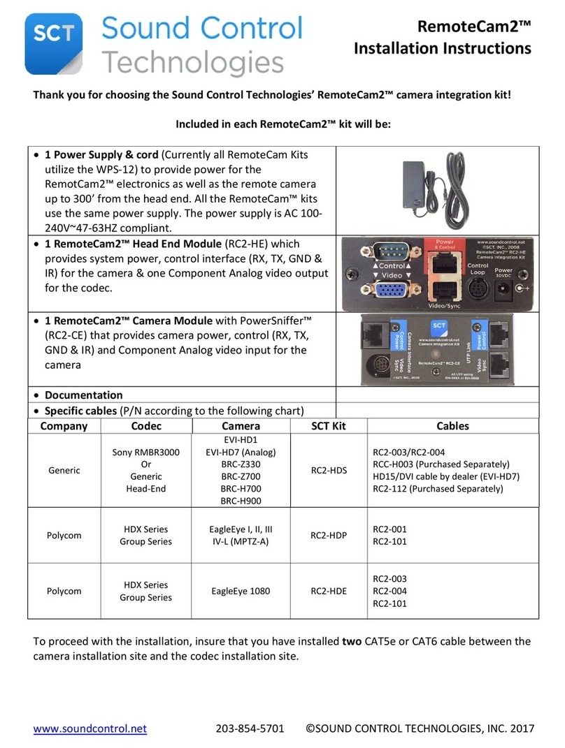
www.soundcontrol.net 203-854-5701 ©SOUND CONTROL TECHNOLOGIES, INC. 2017
Minimum distance should be approximately 30’/9M.
The cable must be wired for either UTP 568A or UTP 568B. Please use the above scheme.
To install the RemoteCam5™ Kit, follow this step-by-step guide:
•
Test and verify the Cat5e or Cat6 cable for UTP 568A or 568B wiring: See steps 2 & 3.
•Install the RC5-HE Head-End Module at the rack/equipment location.
•Connect the Cat5e or Cat6 cable to the RJ45 connector labelled on the RC5-HE module.
•Connect the power supply to the RC5-HE Module.
•
Wait to connect the cable to the RC5-CE until steps 3 & 4 are completed.
At the camera location connect the PowerSniffer™ to the CAT5e or CAT6 cable.
If the cable is properly terminated it will display 8 green LEDs. See image at left.
Any other result, please re-terminate.
•Step 4
•
Disconnect the power supply from the RC5-HE
•Step 5
•Connect the CAT5e or CAT6 cable to the RJ45 connector labelled to the RC5-CE Camera Module.
•Connect provided cables between codec and RC5-HE module. The codec (or second camera or touch panel)
can connect to Port 1 or Port 2 of the RC5-HE.
•Step 7
•Connect provided cables between camera and RC5-CE module.
•Connect the power supply to RC5-HE module
•LED Behavior:
•Head-End Module HDCP LED: Blinking = HDCP Inactive, Solid = HDCP Active
•Head-End Module LED: Blinking Red = No Link, Blinking Red to Green = Active
•Camera Module: LED will be Red until Link is established, Solid Green when is Active

