Sound Magus PK600.1M User manual
PK600.1M / PK1000.1M
PK700.4M / PK1400.4M
Congratulations on purchasing your SOUNDMAGUS amplifier. Please
read this manual in order to fully understand how to get the best results
from this product and ensure that all advice on how to look after the
product is followed.
Thank you for buying SOUNDMAGUS, we hope you enjoy listening to your
product as much as we enjoyed creating it.
An aftermarket audio amplifier will place an additional load on the vehicles
charging system.
Most modern vehicles have sufficient capacity in the charging system as
not all the electrical components of the vehicle will be switched on at once.
Check the fuse rating of the amplifier and use this as the peak current
requirement.
Generally the continuous current draw will be a third of the peak current.
ATTENTION
INTRODUCTION
FEATURES
High Power Type, Compact Products
High Reliability Full Mosfet Design
Overload, shortcircuit, thermal, low voltage protection
Rohs Compliant
High Pass / Low Pass Filter And Subsonic Adjustable
Bassbosst frequency and level adjustable
High efficiency, Energy-saving digital automotive amplifier
Clip limit functionand Q factor adjustable
1 2
PK600.1M/PK1000.1M
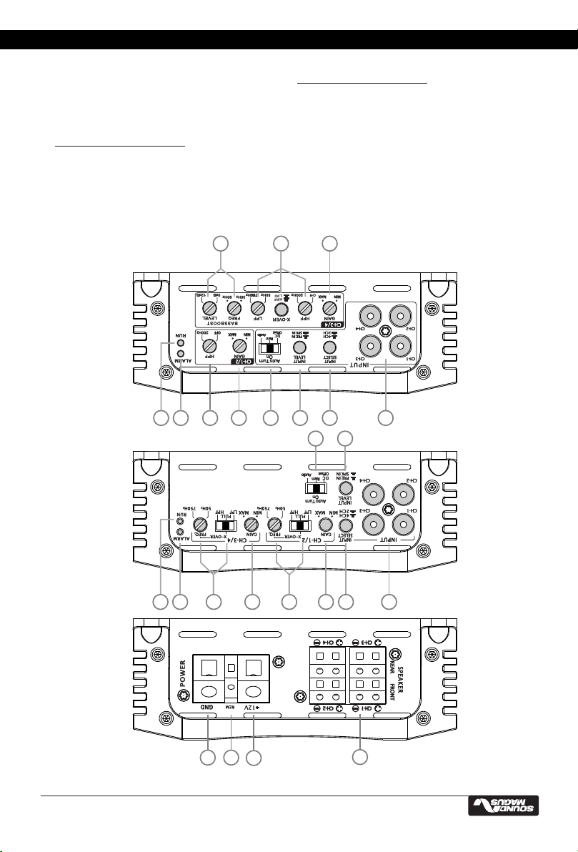
PANEL LAYOUT
PK600.1M
PK1000.1M
56 7
2019 22 23
123 4
56 7 8910
11
2119 20 22 23 24
25
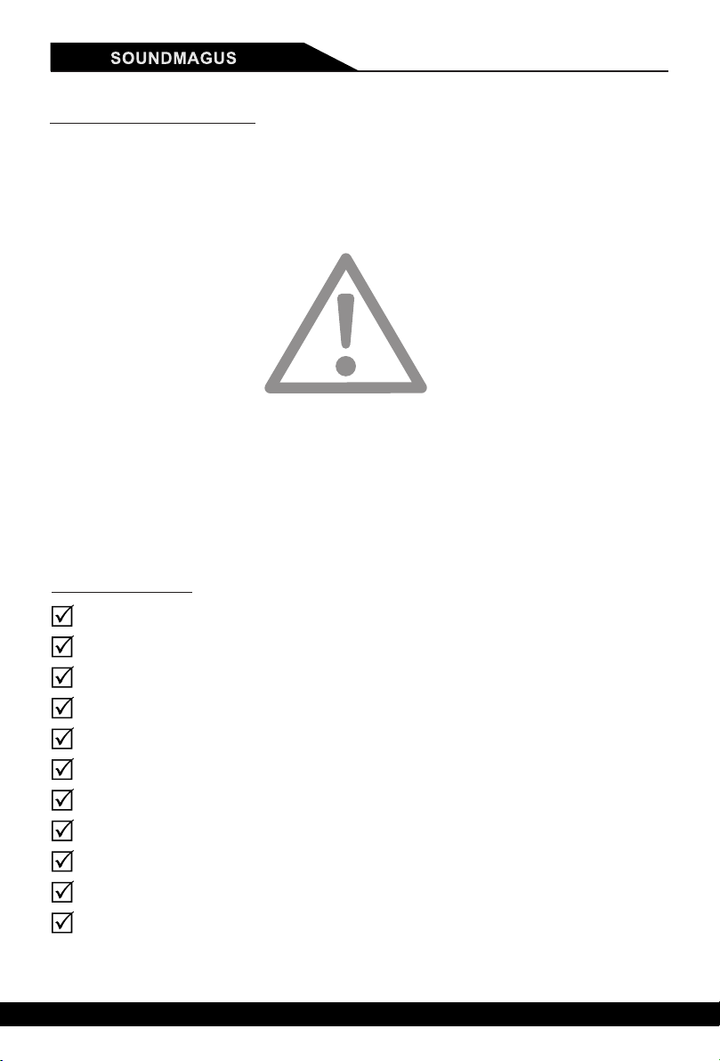
1. SPEAKERS
Connect speakers/subwoofers to these terminals. Be sure to check wire for proper polarity.
Never connect the speaker cables to chassis ground.
2. +12 Volt Power
Connect this terminal through a FUSE or CIRCUIT BREAKER to the positive terminal of the
vehicle battery or the positive terminal of an isolated audio system battery.
Warning: Always protect this power cable by installing a fuse or circuit breaker of the appropriate
size within 18 inches (45cm) of the battery terminal connection.
3.Remote Turn On
This terminal turns on the amplifier when (+)12 volt is applied to it . Connect it to the remote
turn on lead of the head unit or signal source.
MCU Power Management (PK700.4M/PK1400.4M only)
High / Low Level Input Switch (PK700.4M/PK1400.4M only)
Auto Turn - on / off Functions (PK700.4M/PK1400.4M only)
Congratulations on purchasing your SOUNDMAGUS amplifier. Please
read this manual in order to fully understand how to get the best results
from this product and ensure that all advice on how to look after the
product is followed.
Thank you for buying SOUNDMAGUS, we hope you enjoy listening to your
product as much as we enjoyed creating it.
An aftermarket audio amplifier will place an additional load on the vehicles
charging system.
Most modern vehicles have sufficient capacity in the charging system as
not all the electrical components of the vehicle will be switched on at once.
Check the fuse rating of the amplifier and use this as the peak current
requirement.
Generally the continuous current draw will be a third of the peak current.
ATTENTION
INTRODUCTION
FEATURES
High Power Type, Compact Products
High Reliability Full Mosfet Design
Overload, shortcircuit, thermal, low voltage protection
Rohs Compliant
High Pass / Low Pass Filter And Subsonic Adjustable
Bassbosst frequency and level adjustable
High efficiency, Energy-saving digital automotive amplifier
Clip limit functionand Q factor adjustable
1 2
PK600.1M/PK1000.1M
PANEL LAYOUT
PK600.1M
PK1000.1M
56 7
2019 22 23
123 4
56 7 8910
11
2119 20 22 23 24
25
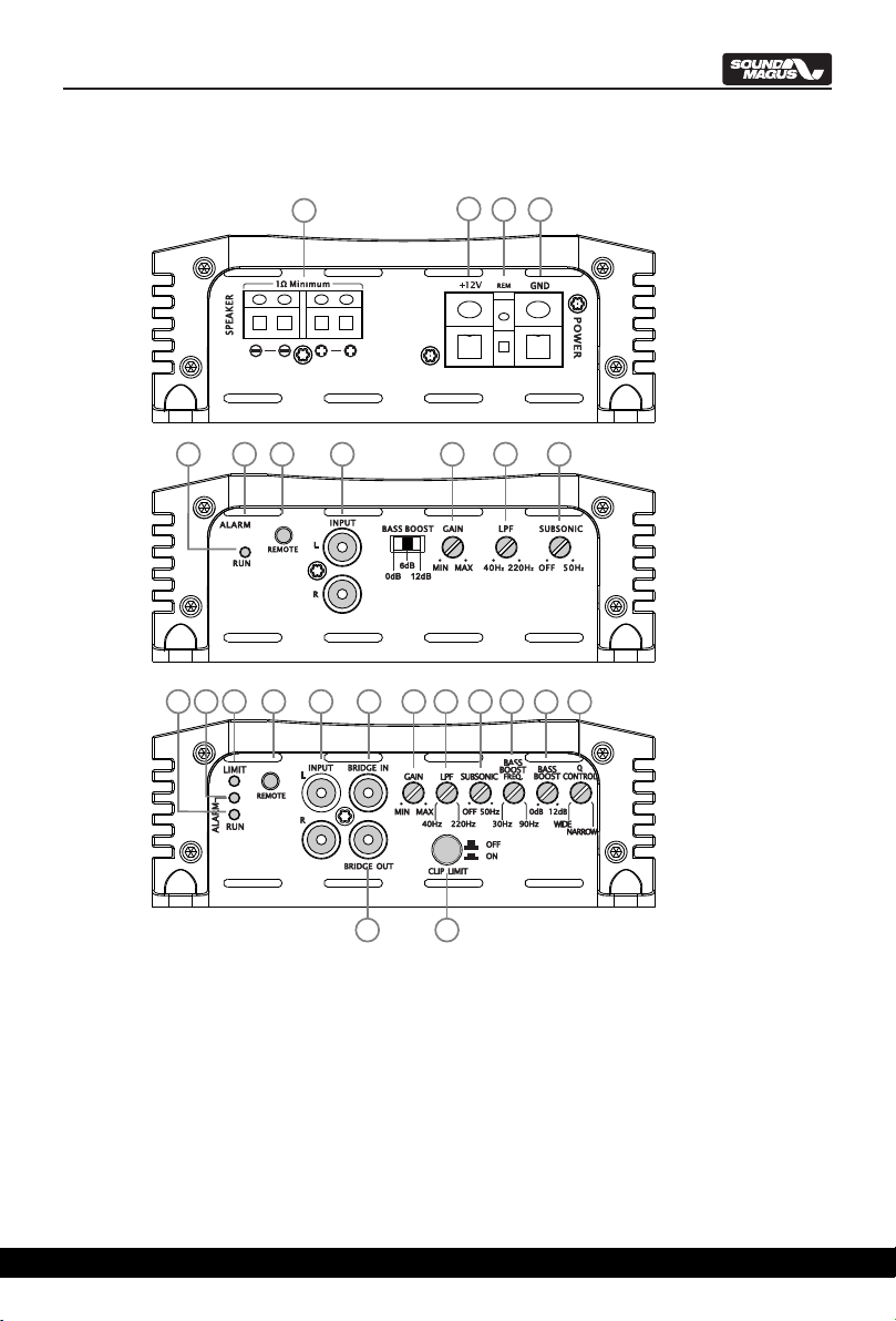
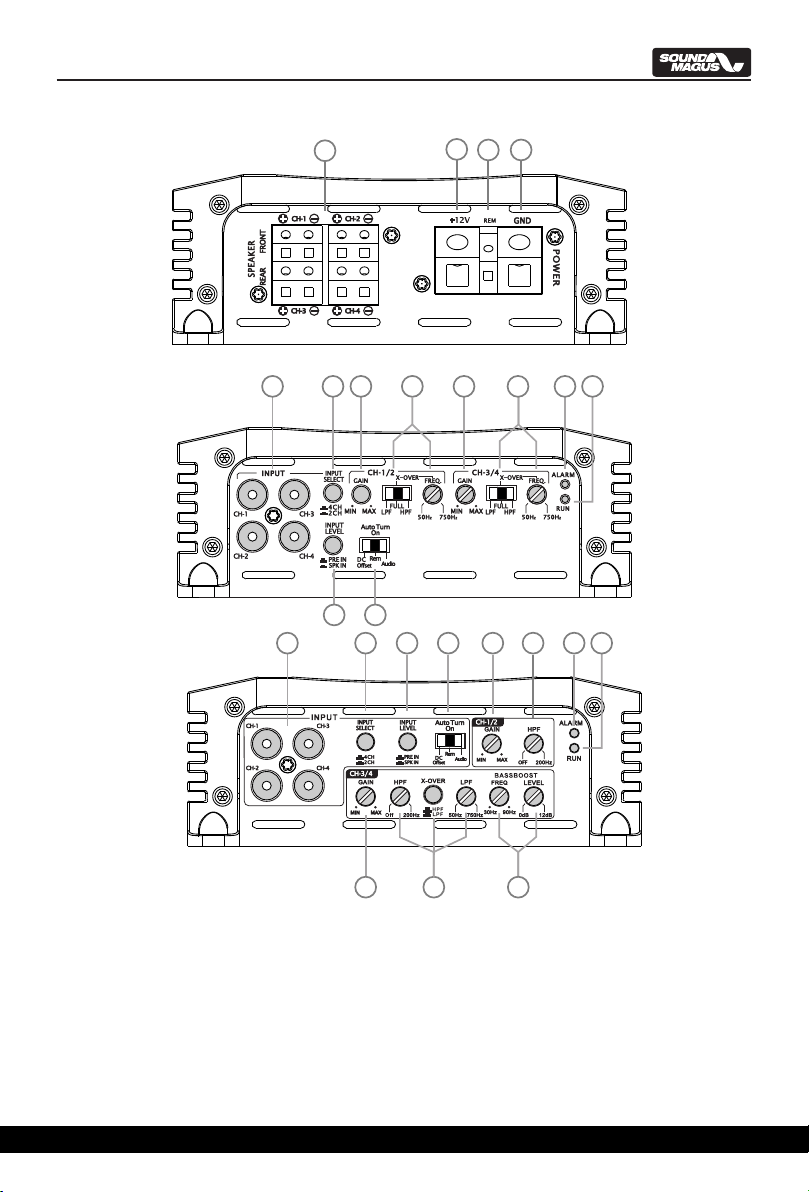
1. SPEAKERS
Connect speakers/subwoofers to these terminals. Be sure to check wire for proper polarity.
Never connect the speaker cables to chassis ground.
2. +12 Volt Power
Connect this terminal through a FUSE or CIRCUIT BREAKER to the positive terminal of the
vehicle battery or the positive terminal of an isolated audio system battery.
Warning: Always protect this power cable by installing a fuse or circuit breaker of the appropriate
size within 18 inches (45cm) of the battery terminal connection.
3.Remote Turn On
This terminal turns on the amplifier when (+)12 volt is applied to it . Connect it to the remote
turn on lead of the head unit or signal source.
MCU Power Management (PK700.4M/PK1400.4M only)
High / Low Level Input Switch (PK700.4M/PK1400.4M only)
Auto Turn - on / off Functions (PK700.4M/PK1400.4M only)

4.GND
Connect this cable directly to the frame of the vehicle. Make sure the metal frame has been
stripped of all paint down to the bare metal. Use the shortest distance possible. It is always a good
idea to replace the factory ground at this time with a larger cable equal to the new amplifier power
cable or larger.
CAUTION: Do not connect this terminal directly to the vehicle battery ground terminal or any other
factory ground points.
5.GIAN
The level control will match the amplifiers sensitivity to the source units signal voltage. The
Operating range is 200mV minimum to 5V maximum. This is NOT a volume control!
6.LPF
This control is used to select the desired low pass x-over frequency. The frequency can be
adjusted from 40Hz to 220Hz for all bass mono models.
7. Subsonic Filter Control
This control can filter out unwanted low frequency from 10Hz (OFF) to 50Hz. This function will
increase the power handling of your woofers.
8. Bass Boost Frequency
By adjusting these two knobs, you can boost a wanted frequency to a wanted level. The center
boost frequency is adjustable from 30Hz to 90Hz,
9. BASSBOOST
This knob adjust the boost level of the bassboost center frequency.It can be adjus-ted from 0 to
12dB, Combining with bassboost frequency, you can accurately match the amplifier performance to
woofer response.
10. Q-Control
This knob adjust the curve shape of bassboost. Turn it to narrow side will make the boosted
frequency narrow and sharp,turn it to wide will extend the boosted frequency range. Combining with
bassboost frequency and bassboost level adjusting,you can a perfect bass response matching get
your system.
11. CLIP LIMIT Switch
This switch control the output clip limit on/off . on, the amplifier will control the When switched
output level and reduce the distortion. This will keep your amplifier at a low distortion at at clip point
clipped signal.
12. X-over mode and frequency Control (Only PK1400.4M )
These controls allow control over the frequencies played for PK1400.4M. There is an option
for Low Pass, Full Range or High Pass. In LP mode the frequency range is from 50Hz to
200Hz(PK1400.4M is from 50Hz to 750Hz) , In HP mode the frequency range is from 15Hz to 200Hz.
13. Bass Boost Frequency and Level Control
By adjusting these two knobs, you can boost a wanted frequency to a wanted level. The center
boost frequency is adjustable from 30Hz to 90Hz, the boost level is adjustable from 0dB to 12dB.
14. HPF
This control is used to set the HPF crossover frequency for the front amplifier er channel. The
frequency is adjustable between OFF and 200Hz.
CONTROL FUNCTIONS
34
15. LPF/FULL/HPF selector & frequency adjustive knob
This switch and knob control Low Pass Filter, High Pass and Full pass function. When set to
LPF, the amplifier will cut off high frequencies and should be used driving subwoofers. When set to
HPF, the amplifier will cut off low frequencies and should be used driving full range speakers or
tweeter. When set to Full, Full range of frequencies are reproduced and output to the speakers. In
another words the filters are “OFF”.
16. 4CH/2CH Switch(PK700.4M/PK1400.4M)
This knob switch 2ch/4ch input mode. When press in, Amplifier works at 2CH input mode, CH-B
input will be paralleled to CH-A, CH-B input jack will be dummy. When pressed knob out, Amplifier
will work at 4CH mode.
PK1400.4M
23 514
16
12 13
5
17 18 19
20
PK700.4M/PK1400.4M
123 4
PK700.4M
23 16 515 515 19
20
17 18

56
17. INPUT LEVEL(PK700.4M/PK1400.4M only)
The amplifier has dual input sensitivity differential inputs which will receive either High level
(Speaker output) or Low level (RCA) signals from your car stereo's source unit.
When switch to PRE IN, The signal can be delivered to the amplifier using the low level RCA
outputs on the source unit.
When switch to SPK IN, The high-level signal can be run from the source unit’s speaker
outputs to the stereo RCA input on the end panel of the amplifier using the HL01.
18. Auto Turn On(PK700.4M/PK1400.4M only)
For auto turn on/off mode, PK1400.4M amplifier offer three options: DC Offset/Rem/Audio.
REM: When auto turn on to REM, please connect the unit REM terminal to the source unit
remote terminal with an 18AWG cable. This is the preferred mode.
DC Offset: If the OEM source unit has no REM signal output, You can choose DC Offset
(Meanwhile,Input select switch to SPK IN mode),DC Offset can turn on/off PK series
amp by detecting the 6V DC Offset from the OEM source unit terminal.
AUDIO: Audio mode can turn ON/OFF PK700.4M and PK1400.4M amp by detecting the audio
signal from source unit. Note: If the volume is too Low, The amp may fail to turn on. So please check
if the source unit volume is properly set.
19. RUN
This LED will light up when amplifier works properly.
20. ALARM
The red LED will light up and will be flashing if there is a fault presented to the amplifier. Please
disconnect the amplifier and resolve the fault before reconnecting the amplifier.
21. Limit Indicator
This LED will light up when output clipped or amplifier get over heat. When limit
indicator light up, the amplifier will hold or reduce output power to protect subwoofer and amplifier.
Please turn down volume or cool down the amplifier when this indicator
light up continually.
22. REMOTE
Connect the remote controller to control the Subwoofer amplifier volume from the driver seat
location, for ease of adjustment during playing.
23. RCA input jacks
These RCA input jacks are for use with source units that have RCA outputs. A source unit with
a minimum level of 200mV is required for proper operation. The use of high quality twisted pair
cables is recommended to decrease the possibility of radiated noise entering the system.
24. Bridge In
This RCA jack receives signal from the master amplifier when this amplifier is bridged as
slave. DO NOT use input jacks when the amplifier is working as slave. All the functions will be
adjusted by the master amplifier.
25. Bridge Out
This RCA output send out bridge signal to another same X-series amplifier in bridging
configuration. All the functions will be adjusted by the master amplifier.
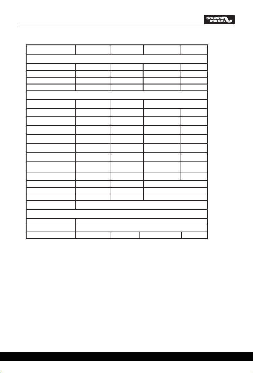
Select cable and fuse according to the following table.
CONNECTING THE AMPLIFIER
MODEL
CABLE
FUSE
PK600.1M PK1000.1M PK700.4M PK1400.4M
6 # 4 # 4-6 #
80 A 120 A 80 A 100 A
6 #
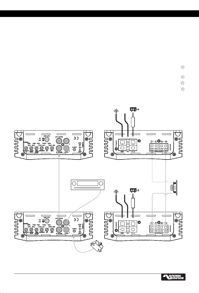
WIRING DIAGRAM
Mono Amplifier wiring (One woofer load)
Mono Amplifier wiring (Two woofer load)
FUSE
RCA signal
Optional Remote Bass Level Control
Source Unit
FUSE
RCA signal
Optional Remote Bass Level Control
Source Unit
1Ohm Minimum
2Ohm Minimum
2Ohm Minimum
(PK600.1M 2Ohm Minimum)
(PK600.1M 4Ohm Minimum)
(PK600.1M 4Ohm Minimum)
Connect the amplifiers ground cable to a close, bare metal part of the frame or chassis. Use a
nut and bolt, Not a screw! The ground cable must be at least the same size as the +12Volt
cable.
Connect the remote terminal to remote output of the head unit using 16 gauge (or heavier)
wire.
Connect the fuse holder within 18”(45cm) of the car battery, and run the selected cable from
this fuse to the amplifier.
Connect all the inputs with high-quality cables. Connect Remote Control if necessary.
Insert fuse(s) into the battery fuse holder(s).
If using a subwoofer for 2-CH and 4-CH, bridge the channels by using the Left “+” and the
Right “-“ terminals.

56
17. INPUT LEVEL(PK700.4M/PK1400.4M only)
The amplifier has dual input sensitivity differential inputs which will receive either High level
(Speaker output) or Low level (RCA) signals from your car stereo's source unit.
When switch to PRE IN, The signal can be delivered to the amplifier using the low level RCA
outputs on the source unit.
When switch to SPK IN, The high-level signal can be run from the source unit’s speaker
outputs to the stereo RCA input on the end panel of the amplifier using the HL01.
18. Auto Turn On(PK700.4M/PK1400.4M only)
For auto turn on/off mode, PK1400.4M amplifier offer three options: DC Offset/Rem/Audio.
REM: When auto turn on to REM, please connect the unit REM terminal to the source unit
remote terminal with an 18AWG cable. This is the preferred mode.
DC Offset: If the OEM source unit has no REM signal output, You can choose DC Offset
(Meanwhile,Input select switch to SPK IN mode),DC Offset can turn on/off PK series
amp by detecting the 6V DC Offset from the OEM source unit terminal.
AUDIO: Audio mode can turn ON/OFF PK700.4M and PK1400.4M amp by detecting the audio
signal from source unit. Note: If the volume is too Low, The amp may fail to turn on. So please check
if the source unit volume is properly set.
19. RUN
This LED will light up when amplifier works properly.
20. ALARM
The red LED will light up and will be flashing if there is a fault presented to the amplifier. Please
disconnect the amplifier and resolve the fault before reconnecting the amplifier.
21. Limit Indicator
This LED will light up when output clipped or amplifier get over heat. When limit
indicator light up, the amplifier will hold or reduce output power to protect subwoofer and amplifier.
Please turn down volume or cool down the amplifier when this indicator
light up continually.
22. REMOTE
Connect the remote controller to control the Subwoofer amplifier volume from the driver seat
location, for ease of adjustment during playing.
23. RCA input jacks
These RCA input jacks are for use with source units that have RCA outputs. A source unit with
a minimum level of 200mV is required for proper operation. The use of high quality twisted pair
cables is recommended to decrease the possibility of radiated noise entering the system.
24. Bridge In
This RCA jack receives signal from the master amplifier when this amplifier is bridged as
slave. DO NOT use input jacks when the amplifier is working as slave. All the functions will be
adjusted by the master amplifier.
25. Bridge Out
This RCA output send out bridge signal to another same X-series amplifier in bridging
configuration. All the functions will be adjusted by the master amplifier.
Select cable and fuse according to the following table.
CONNECTING THE AMPLIFIER
MODEL
CABLE
FUSE
PK600.1M PK1000.1M PK700.4M PK1400.4M
6 # 4 # 4-6 #
80 A 120 A 80 A 100 A
6 #
WIRING DIAGRAM
Mono Amplifier wiring (One woofer load)
Mono Amplifier wiring (Two woofer load)
FUSE
RCA signal
Optional Remote Bass Level Control
Source Unit
FUSE
RCA signal
Optional Remote Bass Level Control
Source Unit
1Ohm Minimum
2Ohm Minimum
2Ohm Minimum
(PK600.1M 2Ohm Minimum)
(PK600.1M 4Ohm Minimum)
(PK600.1M 4Ohm Minimum)
Connect the amplifiers ground cable to a close, bare metal part of the frame or chassis. Use a
nut and bolt, Not a screw! The ground cable must be at least the same size as the +12Volt
cable.
Connect the remote terminal to remote output of the head unit using 16 gauge (or heavier)
wire.
Connect the fuse holder within 18”(45cm) of the car battery, and run the selected cable from
this fuse to the amplifier.
Connect all the inputs with high-quality cables. Connect Remote Control if necessary.
Insert fuse(s) into the battery fuse holder(s).
If using a subwoofer for 2-CH and 4-CH, bridge the channels by using the Left “+” and the
Right “-“ terminals.

78
PK1000.1M Bridged mode
FUSE
RCA signal
Optional Remote Bass Level Control
Source Unit
2Ohm Minimum
FUSE
REM
REM
Amp # 1
MASTER
Amp # 2
SLAVE
Amp # 1
MASTER
Amp # 2
SLAVE
IMPORTANT
When bridging two amplifiers you should use same model amplifiers.
Please make sure the negative speaker terminal of two amplifiers are connected by
the same gauge cables as the positive terminal being used.
DO NOT connect any signal cables to the input RCA jacks when bridged as slave unit.
All the functions will be disabled on slave amplifier when bridged. It will be adjusted by
the master amplifier.
PK700.4M/PK1400.4M wiring (Take PK1400.4M as an example)
Four-channel mode
FUSE
RCA signal
Source Unit
CRO SSO VER
2-Ohm to 4-Ohm
CRO SSO VER
2-Ohm to 4-Ohm
4-Ohm to 8-Ohm
PK700.4M/PK1400.4M wiring (Take PK1400.4M as an example)
Three-channel mode
FUSE
RCA signal
Source Unit
CRO SSO VER
2-Ohm to 4-Ohm
CRO SSO VER
2-Ohm to 4-Ohm
CRO SSO VER
2-Ohm to 4-Ohm
CRO SSO VER
2-Ohm to 4-Ohm
RCA LOW LEVEL or SPEAKER HIGH LEVEL
signals via optional Hl01 Adapter
RCA LOW LEVEL or SPEAKER HIGH LEVEL
signals via optional Hl01 Adapter

910
Symptom Possible Re medy
Amp lifie r
will not
power up
Check to make s ure you have a good ground connection.
Check that there is battery power on the (+)term inal .
Check all fuses , replace if necess ary .
Make s ure that the Protection LED is not illuminated.
Prote ction
LED Come s on
Check for short circuits on s peake r leads .
Check the s p eaker load not beyond the m inim um load.
Rem ove s peaker lead, and reset the amplifier. If the protectio n LED s till
Com es on, then the amplifier is faulty and needs s ervicing .
No output C heck that the RCA audio cables are plugged into the proper inpu ts .
Check all speakers wiring.
Check the headunit output an d the amplifier level setting .
Low output Res et the level Control.
Check the C rossover Con trol s ettings .
High hiss in
The spe akers
Check the R C A cable is not s horted to power ground at am plifier s ide.
Check the am plifie r grounding.
Distorted
so und
Check that the Inpu t level control is s et to m atch the s ignal level of the head unit.
Alw ays tr y to s et the Input level as low as possible.
Check that all crossover frequencies are properly s et.
Check for short circuits on the s peaker leads .
Amp lifie r ge ts
Ve ry h ot
Check that the minimum load im pedance for the am plifier m odel is correct.
Check that there is good air circulation around the am plifier. In s om e applications,
It m ay be necessary to add an external cooling fan.
TROUBLE SHOOTING
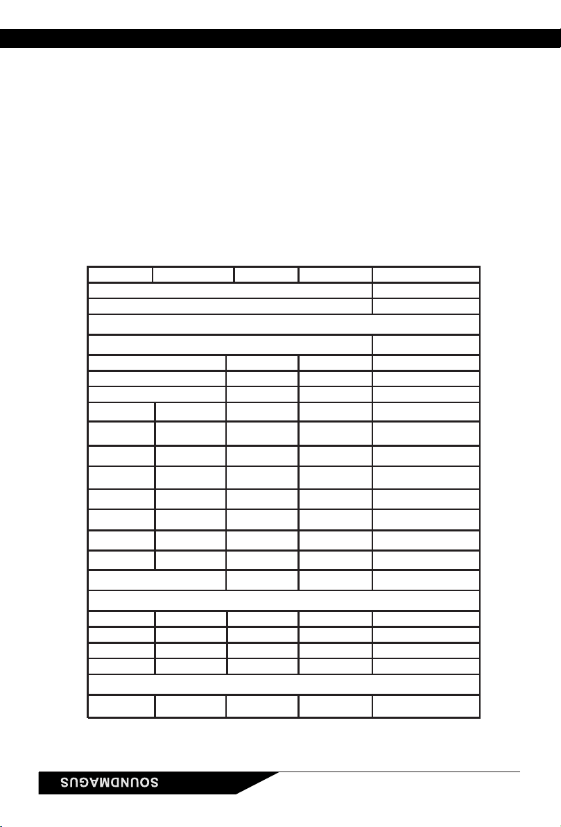
SPECIFICATIONS
238
Length ( mm )
Model PK600.1M
1Ohm Load 1000W x 1
2Ohm Load 600W x 1
4Ohm Load 400W x 1
Bridged 4Ohm Load
Input Level 0.2 5V~
Frequency Response 15Hz 220Hz~
LPF 40Hz 220Hz~
Subsonic/HPF OFF 50Hz~
Bass Boost Level
50Hz
0dB/6dB/12dB
Intelligent Power
S/N Ratio >70dB(1W)
Minimum Load
Voltage Range 8.3V 16V~
Components & PCB
Height ( mm )
Width ( mm )
RMS Power at 14.4V ( THD < 1% )
Features
0.2 5V~
15Hz 220Hz~
40Hz 220Hz~
OFF 50Hz~
DIMENSION
>70dB(1W)
8.3V 16V~
1 Ohm
30Hz 90Hz~
0dB 12dB~
PK1000.1M
650W x 1
400W x 1
355
LPF/Subsonic
X-over Type
Bass Boost Frequency
N/A
Management System
Bass Remote YES YES
YES
2 Ohm
N/AN/A
N/A
LPF / Subsonic
PK700.4M
275
8.3V 16V~
N/A
20~20KHz
PK1400.4M
300W x 4
400W x 4
800W x 2
345
N/A
50~750Hz
10~200Hz
30Hz 90Hz~
0dB 12dB~
N/A
>70dB(1W)
LPF / HPF
20~20KHz
LPF/FULL/ HPF
50~750Hz
50~750Hz
N/A
N/A
>70dB(1W)
170W x 4
100W x 4
360W x 2
N/A
N/A
SPK IN:0.4 10V~
PRE IN:0.2 5V~
2 Ohm
SMD Parts / Double side FR-4 PCB
150
56
910
Symptom Possible Re medy
Amp lifie r
will not
power up
Check to make s ure you have a good ground connection.
Check that there is battery power on the (+)term inal .
Check all fuses , replace if necess ary .
Make s ure that the Protection LED is not illuminated.
Prote ction
LED Come s on
Check for short circuits on s peake r leads .
Check the s p eaker load not beyond the m inim um load.
Rem ove s peaker lead, and reset the amplifier. If the protectio n LED s till
Com es on, then the amplifier is faulty and needs s ervicing .
No output C heck that the RCA audio cables are plugged into the proper inpu ts .
Check all speakers wiring.
Check the headunit output an d the amplifier level setting .
Low output Res et the level Control.
Check the C rossover Con trol s ettings .
High hiss in
The spe akers
Check the R C A cable is not s horted to power ground at am plifier s ide.
Check the am plifie r grounding.
Distorted
so und
Check that the Inpu t level control is s et to m atch the s ignal level of the head unit.
Alw ays tr y to s et the Input level as low as possible.
Check that all crossover frequencies are properly s et.
Check for short circuits on the s peaker leads .
Amp lifie r ge ts
Ve ry h ot
Check that the minimum load im pedance for the am plifier m odel is correct.
Check that there is good air circulation around the am plifier. In s om e applications,
It m ay be necessary to add an external cooling fan.
TROUBLE SHOOTING
SPECIFICATIONS
238
Length ( mm )
Model PK600.1M
1Ohm Load 1000W x 1
2Ohm Load 600W x 1
4Ohm Load 400W x 1
Bridged 4Ohm Load
Input Level 0.2 5V~
Frequency Response 15Hz 220Hz~
LPF 40Hz 220Hz~
Subsonic/HPF OFF 50Hz~
Bass Boost Level
50Hz
0dB/6dB/12dB
Intelligent Power
S/N Ratio >70dB(1W)
Minimum Load
Voltage Range 8.3V 16V~
Components & PCB
Height ( mm )
Width ( mm )
RMS Power at 14.4V ( THD < 1% )
Features
0.2 5V~
15Hz 220Hz~
40Hz 220Hz~
OFF 50Hz~
DIMENSION
>70dB(1W)
8.3V 16V~
1 Ohm
30Hz 90Hz~
0dB 12dB~
PK1000.1M
650W x 1
400W x 1
355
LPF/Subsonic
X-over Type
Bass Boost Frequency
N/A
Management System
Bass Remote YES YES
YES
2 Ohm
N/AN/A
N/A
LPF / Subsonic
PK700.4M
275
8.3V 16V~
N/A
20~20KHz
PK1400.4M
300W x 4
400W x 4
800W x 2
345
N/A
50~750Hz
10~200Hz
30Hz 90Hz~
0dB 12dB~
N/A
>70dB(1W)
LPF / HPF
20~20KHz
LPF/FULL/ HPF
50~750Hz
50~750Hz
N/A
N/A
>70dB(1W)
170W x 4
100W x 4
360W x 2
N/A
N/A
SPK IN:0.4 10V~
PRE IN:0.2 5V~
2 Ohm
SMD Parts / Double side FR-4 PCB
150
56
10
规格参数
11
若有其 他问 题请联系“ 圣美歌指定 安装店”或 登陆圣美歌 官方 网www.soundmagus.cn(中
文域名“圣美歌.中国”)获得相 关技术支持。
故障对策
电源指 示灯 不亮
检查音频信号源的音量控制器
电源指示灯亮,
但仍没 有声 音
检查功放的电平调节钮(GAIN)
检查音频信号线及其连接情况
检查扬 声器 是否损坏及 其连接线是 否正确
检查电源线和接地线是否正确连接
检查开关控制线是否和机头的音源设备正确连接
检查所 有的 保险管是否 损坏
检查蓄 电池 电压是否过 低
功放处 于保 护状态
检查功放扬声器输出端是否短路,扬声器是否损坏
检查功 放温 度是否过高
检查扬 声器 阻抗是否正 确
检查电池电压是否过低
音色失 真
检查音源设备音量是否过大,超出了本机或扬声器的正
常工作 范围
检查功 放输 入信号电平GAIN旋钮是否处在合适的位置
检查扬声器是否已损坏
功放不停的开关
检查功放接地线是否接触良好
检查蓄电池接线端子和电源端子是否接触良好
检查蓄电池电源电压是否过低
遥控开关机的连接线接触不良
故 障 检测方法
一个声 道不 工作
检查此 声道 的音频信号 线的连接情 况
检查此 声道 扬声器输出 端子的连接 情况
检查音 源声 道平衡调节 器是否调整 到中间
检测此声道对应的扬声器是否损坏
长度 ( 毫米 )
型号
1欧姆负载
2欧姆负载
4欧姆负载
输入信号电平
频率响应
滤波器类型
低通频率
次低通频率/高通频率
低音增益调节频率
低音增益调节
智能功率管理系
信噪比
最小负载
电压范围
可选遥控
零部件 & PCB
高度 ( 毫米 )
宽度 ( 毫米 )
14.4V额定功率 ( 失真度<1% )
产品特征
低通 全通 高通/ /低通 次低通/
SMT & 双面电路板
低通 高通/
2 欧姆
238
PK600.1M
1000W x 1
600W x 1
400W x 1
桥接4欧姆负载
0.2 5V~
15Hz 220Hz~
40Hz 220Hz~
OFF 50Hz~
50Hz
0dB/6dB/12dB
>70dB(1W)
8.3V 16V~
0.2 5V~
15Hz 220Hz~
40Hz 220Hz~
OFF 50Hz~
>70dB(1W)
8.3V 16V~
30Hz 90Hz~
0dB 12dB~
PK1000.1M
650W x 1
400W x 1
355
N/A
是 是
YES
否否
否
PK700.4M
275
8.3V 16V~
否
20~20KHz
PK1400.4M
300W x 4
400W x 4
800W x 2
345
否
20~20KHz
50~750Hz
10~200Hz
30Hz 90Hz~
0dB 12dB~
否
>70dB(1W)
50~750Hz
50~750Hz
否
否
>70dB(1W)
170W x 4
100W x 4
360W x 2
否
否
1 欧姆
低通 高通/
2 欧姆
产品尺寸
扬声器输入:0.4~10V
RCA输入:0.2 5V~
150
56

8
FUSE
RCA 信号
CRO SSO VER
2欧姆 ~ 4欧姆
CRO SSO VER
2欧姆 ~ 4欧姆
4欧姆 ~ 8欧姆
PK700.4M/PK1400.4M 连接图 (以PK1400.4M为例)
3声道连接模式
可选择RCA低电平信号输入或扬声器高电平信号输入,
使用扬声器高电平信号输入时可选择安装HL01。
车载CD机
PK1000.1M 桥接模式
FUSEFUSE
REM
REM
1号功放
主功放
选装的远程音量遥控器
最大输入 信号5V
车载CD机
最小阻抗2欧 姆
1号功放
主功放
2号功放
副功放
2号功放
副功放
双功放 桥接 注意事项:
双功放桥接时,需 使 用 两 台相同型号的功放。
请务必使用与扬声 器 接 线 相同规格的线材直接连 接 两 台 功放的扬声器负极输出 端 子 。
当功放作为副机时 , 不 要 再连接输入信号到其RCA输入端口,只需要用单条RCA信号线连接主功放
的BRIDGE OUT和副 功 放 的BRIDGE IN即可。
当功放作为副机时,所有的信号调节以及遥控功能将失效,副功放将完全受控于主功放。
9
PK700.4M/PK1400.4M 连接图 (以PK1400.4M为例)
4声道连接模式
FUSE
CRO SSO VER
CRO SSO VER
CRO SSO VER
CRO SSO VER
RCA 信号
可选择RCA低电平信号输入或扬声器高电平信号输入,
使用扬声器高电平信号输入时可选择安装HL01。
车载CD机
2欧姆 ~ 4欧姆
2欧姆 ~ 4欧姆
2欧姆 ~ 4欧姆
2欧姆 ~ 4欧姆

功放输入接线图
单声道功放接线图 (连接一 个低音扬声 器)
FUSE
最大输入信号5V
选装的远程音量遥控器
车载CD机
最小阻 抗1欧姆
单声道功放 接线图 (连接两个低音 扬声器)
FUSE
最小阻抗2欧 姆
最小阻抗2欧 姆
选装的远程音量遥控器
最大 输入 信号5 V
车载CD机
(PK600.1M最 小阻抗 1 欧姆)
(PK600.1M最 小阻抗 4欧姆)
安装功放时,请确保固定螺钉不要损伤车辆油箱以及刹车制动、燃油管线和电路设备等管线。
请不要把任何连接线缆裸露在车体外面,当线缆穿过金属、橡皮、塑料时,请保护好线缆,避免绝
缘层损伤。所有连 接 线 都 不要拉得太紧。
为避免干扰,请使用优质屏蔽RCA信号线连接音源设备和功放,RCA插头金属外壳不可接触车体,布
线时电源线和信号线应分置于车身左右两侧,所有线材应尽量远离点火线圈及行车电脑等设备。
功放须安装在较大空间且易于固定的地方,即使在正常工作时,功放也将散发较多的热量,因此请
不要把本机放在过于狭小的密闭空间内或用物体覆盖。
系统安装前请做好相应的车厢布局规划和准备工作,建议您在“圣美歌指定安装店”安装您的功放。
产品安装注意事项
功放满功率工作时消耗电流较大,请使用绝缘良好的优质导线作为电源线,并确保电源线能长期
承受40A以上工作电流,同时也需保证所有接头接触良好。电源线与蓄电池之间必需串接保险管,
保险管安装位置与 蓄 电 池 正12V 接线柱之 间 距 离 不超过20cm。电源线及外接保险管规格要求如
下:
型号 PK600.1M PK1000.1M PK700.4M PK1400.4M
电缆线 6 # 4 # 4-6 #
保险管 80 A 120 A 80 A 100 A
6 #
6
PK1400.4M 23 5
14
16
12 13
5
17 18 19
20
PK700.4M/PK1400.4M
123 4
23 16 515 515 19
20
17 18
PK700.4M
24 BRIDGE IN 双功放桥接时副功放信号输入端子
圣美歌数字 低 音功放具有 双 功 放桥接的功 能 , 您可以把两 台 同型号的功放 桥 接以推动更 大 功 率的
扬声器。当两台功放桥接时有主功放和副功放之分,副功放通过此BRIDGE IN插孔来接收来自
主功放的 同 步控制信 号 ,以实现 全 部功能。 此 时请不要 再 使用副功 放 的其他RCA信号输入插 孔 ,
副功放的所有调节 功 能 也 将全部失效,副功放会 完 全 被 主功放控制。(请参照双功 放 桥 接连接图)
25 BRIDGE OUT 双功放桥接时主 功放 信号输出端 子
当两 台 功放 桥 接时 , 主功放 通过这 个BRIDGE OUT插孔输 出给副 功放同 步控制 信号, 副功放 使用
BRIDGE IN 插孔接收来 自 主 功 放的此信号后,副功放 的 所 有调接功能将全部失效 , 副 功 放会完全
被主功放所控制。(请 参 照 双 功放桥接连接图)
7

12 滤波器 类型 和频率控制 旋钮
这是用于调节低通 滤 波 功 能的开关和旋钮。当低 通 开 关 被按下时,低通滤波功 能 打 开,可以通过
调节低通滤波旋钮 设 定 低 通滤波的截止频率。此 功 能 通 常用于驱动低音扬声器 。 在 低通模式下,
高通滤波器仍然在 工 作 , 此时它可以当作次低音 滤 波 器 ,滤除无法被播放的次 低 音 信号。当低通
开关被按出时,低 通 滤 波 器停止工作,低通频率 调 节 旋 钮也不再起作用。
13 低音增 强的 频率和幅度
这两个 旋 钮配合使 用 可以达 到 完美的 低 音提升效 果 。您可 以 通过调整 频率旋钮 选 择您希 望 提升的
低音中 心 频率,同 时 通过调 整 低音幅 度 提升旋钮 把 这个频 率 点提升到 希望的电 平 。低音 频 率调节
范围是30~90Hz,低音幅度 的 提升范 围 则是0~1 2 d B。 低音提 升功能在 高通和 低 通模式 下 都是有 效
的。
面板布局
PK600.1M/PK1000.1M
PK600.1M
PK1000.1M
56 7
2019 22 23
123 4
56 7 8910
11
2119 20 22 23 24
25
4
18 自动开关机控制模式选择开关(适用于 PK1400.4M) PK700.4M/
PK700.4M/PK1400.4M功放提供三种开机模式给客户选择使用,分别为DC Offset/Rem/Audio模式。
Rem:开 关 切 换 至Rem时,使用 一 条18AWG的线将汽车主机的遥控输出端连接到功放电源端子的
Rem端, 这 是 首 选的开机方法。
DC Offset:如果使用原车主机, 且 没 有REM信号输出,可以选择DC Offset(同时将Input Select
开关切换为SPK IN模式),DC Offset开机模式是检测到原车主机喇叭输出端的6V直流偏移来自动
开启功放。
功放有两种不同的 输 入 灵 敏度,可以接收来自主 机RCA输出的低电平或SPK输出的高电平立体声信
号。
当此按钮切换为PRE IN模式时,是通过主 机 的RCA端将低电平信号输入至功放。
当此按钮切换为SPK IN模式时,是将主机扬声器输出端的高电平信号通过HL01(高 低电平转换/
器)来输入至功放 的RCA端。
17 高/低电平信 号输入切换 开关(适用于 PK1400.4M)PK700.4M/
16 单组/双组RCA输入信 号切换开关(适 用于 MPK700.4M/PK1400.4 )
当此按钮设置为4CH模式时,功放的A组和B组RCA输入端需要分别输入立体声信号,功放的4个声
道将 独 立工 作。当 此按 钮 开关 设 置为2CH模 式 时, 功 放只 需输 入A组的RCA立体声信号,B组即接
入与A组相同的信号。 此 功 能 便于连接只有一组RCA信号输出的音源设备。
这个旋钮及开关的 组 合 用 于调整功放的工作频率 范 围 。 当开关设定在LPF(低通)或H P F (高通)时,相
应的滤波器工作频率就可以通过旋钮在50Hz至750Hz之间进行设定。当推动低音扬声器时,开关应
设置在LPF模式;当推动小口径全频扬声器或中高音扬声器时,开关应设置在HPF模式;当推动较
大 口 径 的 全 频 扬 声 器 时 可 以 设 置 在F U LL (全 通)模 式 。 当 开 关 选 定 在F ULL模 式 时 , 滤 波 器 频 率 调 节
旋钮将没有作用。
15 高通/全通/低通滤波器模式调节开关及旋钮
14 高通频 率调 节
这个旋钮用于调节本组的高通截止频率。高通功能可以滤除扬声器无法播放的过低频率,使扬声器
工作在最佳状态。 当 此 旋 钮逆时针旋到OFF位置时,此滤波器将关闭,低频信号将不被滤除。
当功放处于开机自检状态时,此蓝色工作指示灯熄灭或闪烁,当功放自检完成进入正常工作状态
时,此蓝色工作指 示 灯 为 长亮状态。
19 工作指示 灯
20 自检及保 护状态指示 灯
保护指示灯点亮时表示功放处在开机自检状态或出现故障。当出现短路、过 载、过热以及欠压
保护时此指示灯点亮且功放停止工作。注意:功放处于保护状态时,请及时关机并排除故障,
以免导致功放损坏!如果是过载、短路引起的故障,请及时检查扬声器连接线以及阻抗;如果是
过热引起保护,请检查功放是否有良好的散热条件;如果是电压不足引起的保护,请检查电源接
线以及蓄电池电压 是 否 正 常。
Audio:此模式是通过检测到来自汽车主机输出的音频信号来控制控制功放的开关。
这种自动开机方式要注意原车主机音量的设置,主机的音量太小可能会出现功放无法开启的情
况。
23 输入信号( RCA)端子
本机采用了高性能平衡式输入电路,在确保高保真输入的同时也可以极佳的滤除汽车电流噪
音,使用户彻底摆 脱 电 流 噪音的困扰。请注意:RCA端子外壳不可接地,并应尽量缩短信号线的
长度。
如果您的音源设备 没 有RCA输出接口,可以使 用 圣 美 歌HTL系列信号适配器。
22 音量遥控器插座
此插孔用来连接可选配的圣美歌数字低音功放音量遥控器,音量遥控器可以安装在操控方便的地
方,使您可以在座位上直接控制此功放的输出音量。
21 输出削波、过热限制指示灯
当功放输出削波或温度进入预警范围时,此指示灯会点亮。当工作在满功率状态时,此指示灯会闪烁
。如按下CLIP LIMIT 按钮,此时功放会抑制过高的失真信号。当功放温度升高到预警范围时,此灯会常
亮且功放输出功率会下调,以确保功放的正常工作,此灯常时,请调低音量或改善功放散热条件。
5

11 削波限 制按 钮
削波限制功能按钮ON/OFF。打开时,功放会限制波形的削波幅度在一个较低的范围,从而尽可能的
保持小的失真。
功能简介
1 扬声器 输出 端子
请将扬声器的正极与功放的输出正极相接,其负极与功放的输出负极相接。请勿将扬声器连接线
与功放表面接触,否则会损坏您的功放。我们建议采用AWG (美线标)16#或以上的扬声器专用连接
线。具体连接方法 详 见 扬 声器连接图示(请参考8~11页)。
2 +12V电源输入端子
用于连接12V汽车 蓄 电 池正极端。
注意:为确保功放有充足的电源供应,应使用专用电缆线直接连接于蓄电池的正级,并在距离蓄电
池正极端20厘米内串接保险丝。(电缆线及保险丝规格请参照附表1)
4 电源接 地端 子
用于连接功放接地电缆,电源接地线需要稳固的连接在车体、大梁等导电良好的地方,请使用和电源
线相同规格的线缆,在功放安装位置就近连接车体。请确保接地点接触良好并采取适当的防氧化措
施。
3 遥控开关机端子
用于连接汽车CD机等音源设备的开关机控制输出信号,功放将随着CD机等音源设备的开关而开关。若
使用原车配置的无开关机遥控输出的CD机时,可以选配圣美歌HTL系列适配器实现开关机同步控制功
能。
5 电平调 节旋 钮
本机可以输入电平为 的音频信号,安装调试时,需调整 旋钮使功放输入电平与音源0.2V GAIN~5V
设备输出电平相匹配。(注意:电平调节钮并不是音量调节旋钮,调整到合适的信号输入电平,是完
美音质的基本保证,请配合不同的 机特性调整到合适的电平,电平过高可能会损坏扬声器,也可能CD
产生背景噪声。)
从40Hz到220Hz连续可调的低通滤波器,用于调整功放的低音输出频率范围。(如:调整在120Hz则
低于120Hz的低音信号可以被功放 放 大 输 出)。
6 LPF低通滤波器调 节旋钮
7 SUBSONIC次低音滤 波器 调节旋钮
用于滤除人耳听不到的或扬声器无法重播的次低音频率,从而减少扬声器和功放的无效功率,也
减少系统耗电量。(如 SUBSONIC旋钮调整在40Hz ,则低于40Hz的次低音信号将被功放滤除,不:
被放大并输到出给 扬 声 器 。)
8 BASSBOOST FREQ低音增强 频率调节旋 钮
此旋钮用于调节低音信号增强的中心频率点,您可以根据音响系统的低频特性选择30Hz~90Hz之
间的任意频率点进 行 精 确 提升。(如:此旋钮调整为50Hz时,功放将以对中心点为50Hz频段信号进
行提升。)配合低音增强幅度调节旋钮可以对该频段的提升幅度进行调节。
9 BASSBOOST 低音增强幅度调 节旋钮
此旋钮与 BASSBOOST FREQ 旋钮配合使用,可以将上述BASSBOOST FREQ 选定的低音频率
点做为中心,实现0~12dB 的 幅度提升。(如:前面的BASSBOOST FREQ旋钮调整为50Hz,此处的
BASSBOOST旋 钮 调整为6dB,功放将针对以50Hz为中心的低频信号进行6dB的提升。)
10 低音增强的Q值调节旋钮
这个旋钮可以调节低音增强的频率响应宽窄特性,调到NARROW端,可以使增强的频段变窄,调到
WIDE端可以使增强的频段变宽.和BASSBOOST FREQUENCY, BASSBOOST LEVEL一起使用,可以使
功放和你的系统达到完美匹配的频率响应曲线。
2
特征:
大功率型、紧凑型产品
高电平/低电平输入信号切换(PK700.4M/PK1400.4M)
大容量电解电容,全MOSFET大电流高效率数字电路
过载、短路、低电压、过热保护
无铅工艺绿色环保产品及欧盟安全认证
可调节的高通\低通滤波器、可调节的次低音滤波器
频率、幅度可调节的低音提升功能
削波限制及低音增强的Q值调节功能(PK1000.1M)
高效、节能型数字汽车功放
使用由MCU控制的数字电源平台(PK700.4M/PK1400.4M)
自动开/机控制模式选择开关(PK700.4M/PK1400.4M)
3
This manual suits for next models
3
Table of contents
Other Sound Magus Amplifier manuals


