Sound Magus ET90.4 User manual
OWNER'S MANUAL
ET90.4/ET150.4
SOUNDMAGUS Bluetooth car amplifier

Frequency Response 10~35000Hz, THD<0.1%.
Built-in professional Bluetooth signal processor module.
BT amplifiers accept both RCA input and Bluetooth audio signals.
There are buffered stereo RCA outputs on amplifier. The RCA
outputs duplicate the signal playing on amplifier, either RCA
input or Bluetooth audio.
There's independent Remote output signal available for extra
amplifiers.
SMD dedicated audio chip devices. The extensive use of chip
devices effectively shorten the length between devices.
Thereby greatly reduce the mutual inductance of current and
recessive capacitive interference between the device. That
ensure the fidelity output.
Power supply design:Full Mosfet DC-DC PWM power supply.
Passed ROHS certification.
Overload, Shortcircuit, Thermal, Low voltage protection.
Once Bluetooth connected, the amplifier will automatically
switch the Bluetooth audio signal. Once Bluetooth
disconnected, amplifier will switch back to RCA inputs.
A power amplifier’s performance is only as good as its installation.
Proper installation will maximize the system’s overall performance. It is
recommended that you have our product installed by an authorized
SOUNDMAGUS retailer. However, if you decide to install it by yourself,
please carefully read through this manual and take your time to do a
qualified installation.
RECOMMENDATION
Thank you for purchasing Soundmagus Bluetooth car amplifier.
You have selected a Bluetooth Car audio power amplifier integrated
into the world's most advanced design concepts and techniques.
It is carefully designed for car audio enthusiasts who has pursuit of
high-fidelity sound.
It is built with strong output power, perfect sound quality and perfect
self-protection.
Whether listening to classical music or the world's best rock songs , it
brings you an unprecedented music experience.
All Soundmagus amplifiers use high quality components and produce
under strict quality control
system. We believe it will bring you a long pleasant music trip.
INTRODUCTION FEATURES
4. GND
Connect this cable directly to the frame of the vehicle. Make sure the
metal frame has been stripped of all paint down to the bare metal. Use the
shortest distance possible. It is always a good idea to replace the factory
ground at this time with a larger cable equal to the new amplifier power
cable or larger.
CAUTION: Do not connect this terminal directly to the vehicle battery
ground terminal or any other factory ground points.
5. RCA audio-input
These RCA input jacks are for use with source units that have RCA
outputs. A source unit with a minimum level of 200mV is required for proper
operation. The use of high quality twisted pair cables is recommended to
decrease the possibility of radiated noise entering the system.
6. RCA audio-output
This RCA jack output buffered inputs signal. This buffered output signal
is easy to use for daisy chain amplifier installation.
7. REMOTE-output
Power amplifier with REMOTE output signal alone, can be used to
connect other amplifier, through the REMOTE signal to control the other
amplifier startup and shutdown.
8. GAIN
Gain control regulates the sensitivity of amplifier to match the signal
output voltage of your source unit. The gain control is not a volume
adjustment. Use high quality CD music and increase the volume of your
source unit to 75%. Position the gain at the minimum and then increase
gain slowly(clockwise). Stop at the first sign of distortion, then lower the
gain a little(counter clockwise) to achieve clear undistorted music at the
maximum level.
9. LPF/FULL/HPF selector & frequency adjustive knob
This switch and knob control Low Pass Filter, High Pass Filter and Full
pass function. When set to LPF, the amplifier will cut off high frequencies
and should be used driving subwoofers. When set to HPF, the amplifier will
cut off low frequencies and should be used driving full range speakers or
tweeter. When set to Full, Full range of frequencies are reproduced and
output to the speakers. In another words the filters are “OFF”.
10. ANT
The power amplifier using 2.4G general purpose high gain antenna
antenna gain, maximum can reach 3.5dB.
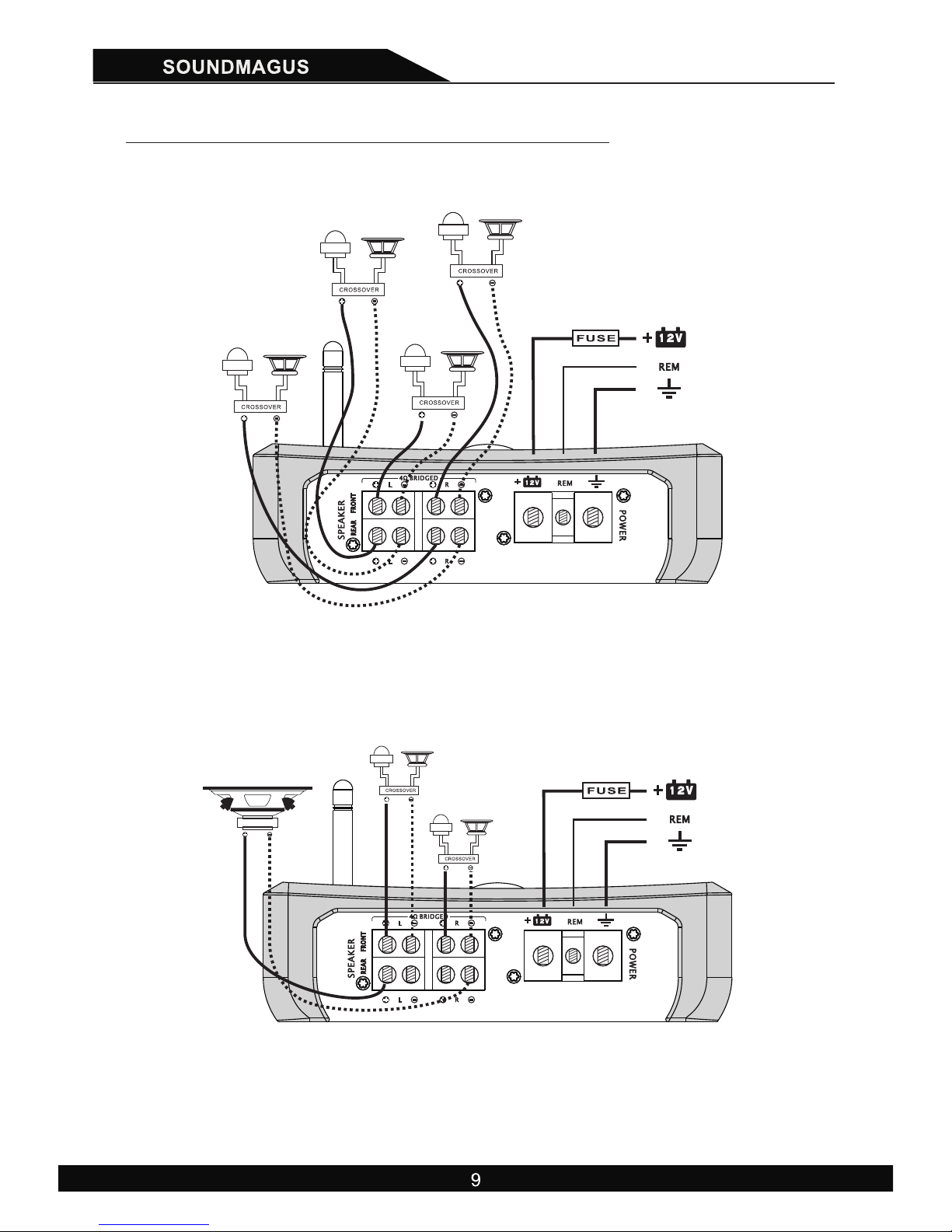
1. SPEAKERS Connection
Connect your speakers correctly which means plus to plus and minus
to minus. Never connect speaker cables with chassis ground directly. It
may destroy your amplifier. We recommend minimum AWG 15#(1.5mm2)
speaker cable. The detailed connection ways are shown in page9.
2. +12V Battery Terminal
The +12 Volt power cable must be connected with a fuse in line near
the battery+ terminal. Please see the table 1 in page 5 to select cable and
fuse.
3. REM
Remote terminal. The remote cable must be connected with source
unit remote terminal so that the amplifier will switch on off automatically
with source unit. If there are two or more amplifiers connected to this
terminal it might be necessary to add an additional telay.
ET90.4/ET150.4
7 8 95 6
8
10
11 12
9
1 2 3 4
CONTROLS & FUNCTIONS

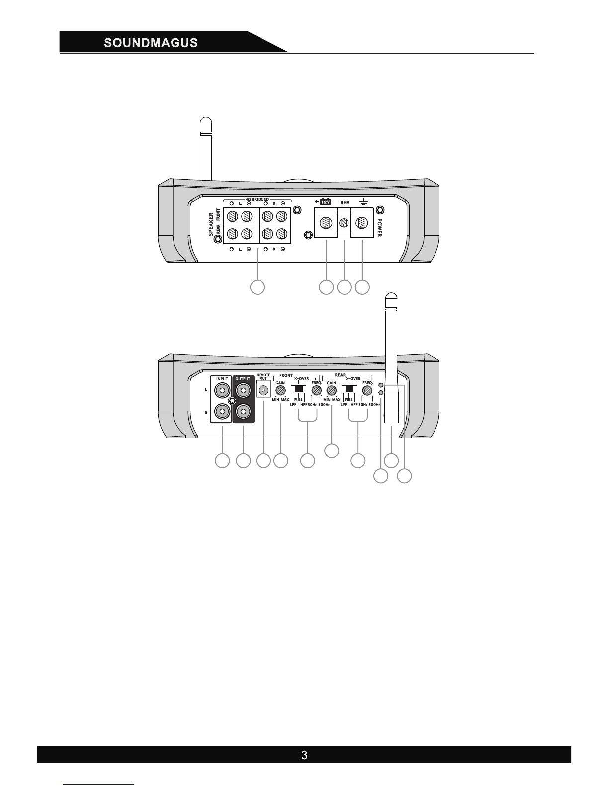
4. GND
Connect this cable directly to the frame of the vehicle. Make sure the
metal frame has been stripped of all paint down to the bare metal. Use the
shortest distance possible. It is always a good idea to replace the factory
ground at this time with a larger cable equal to the new amplifier power
cable or larger.
CAUTION: Do not connect this terminal directly to the vehicle battery
ground terminal or any other factory ground points.
5. RCA audio-input
These RCA input jacks are for use with source units that have RCA
outputs. A source unit with a minimum level of 200mV is required for proper
operation. The use of high quality twisted pair cables is recommended to
decrease the possibility of radiated noise entering the system.
6. RCA audio-output
This RCA jack output buffered inputs signal. This buffered output signal
is easy to use for daisy chain amplifier installation.
7. REMOTE-output
Power amplifier with REMOTE output signal alone, can be used to
connect other amplifier, through the REMOTE signal to control the other
amplifier startup and shutdown.
8. GAIN
Gain control regulates the sensitivity of amplifier to match the signal
output voltage of your source unit. The gain control is not a volume
adjustment. Use high quality CD music and increase the volume of your
source unit to 75%. Position the gain at the minimum and then increase
gain slowly(clockwise). Stop at the first sign of distortion, then lower the
gain a little(counter clockwise) to achieve clear undistorted music at the
maximum level.
9. LPF/FULL/HPF selector & frequency adjustive knob
This switch and knob control Low Pass Filter, High Pass Filter and Full
pass function. When set to LPF, the amplifier will cut off high frequencies
and should be used driving subwoofers. When set to HPF, the amplifier will
cut off low frequencies and should be used driving full range speakers or
tweeter. When set to Full, Full range of frequencies are reproduced and
output to the speakers. In another words the filters are “OFF”.
10. ANT
The power amplifier using 2.4G general purpose high gain antenna
antenna gain, maximum can reach 3.5dB.
1. SPEAKERS Connection
Connect your speakers correctly which means plus to plus and minus
to minus. Never connect speaker cables with chassis ground directly. It
may destroy your amplifier. We recommend minimum AWG 15#(1.5mm2)
speaker cable. The detailed connection ways are shown in page9.
2. +12V Battery Terminal
The +12 Volt power cable must be connected with a fuse in line near
the battery+ terminal. Please see the table 1 in page 5 to select cable and
fuse.
3. REM
Remote terminal. The remote cable must be connected with source
unit remote terminal so that the amplifier will switch on off automatically
with source unit. If there are two or more amplifiers connected to this
terminal it might be necessary to add an additional telay.
ET90.4/ET150.4
7 8 95 6
8
10
11 12
9
1 2 3 4
CONTROLS & FUNCTIONS

Horicontal push direction
Horicontal push direction
Table
Model
Cable
Fuse
ET90.4
40 A
ET150.4
4 - 6 #
60 A
4 - 8 #
11. RUN Indicator
This LED will light up when amplifier work properly. It will flash or shut
down once amplifier in self testing or malfunction.
12. Alarm Indicator
This LED will light up when amplifier detect a fault or shut down to
protect itself from permanent damage. This may caused by one of the
following: Excessive heat, reverse polarity, short circuit or overload. If this
happens please shut off the amplifier and check problem.
PREINSTALLATION
Please prepare sufficiently to layout your car space before installation. We
recommend to have the installation done by an Autho rized
SOUNDMAGUS Dealer.
Please use good insulated power cable to endure longterm above 40A
electronical current. The +12 Volt power cable must be connected with a
fuse in line near 20cm of battery+ terminal. Required current, power cable
and proper external fuse listed as following:
Please use car audio RCA cables, otherwise it may be disturbed. Keep
these cables as short as possible. To avoid disturbances from your car
electronics, please don`t close the existing car cables when you install
the RCA cables.
Don't expose any cables out of car. Please take care insulated cables to
avoid damaging when cables pass through metal, rubber and plastic etc.
Don't install all cables too tight.
The ground wire should be connected directly with the chassis of your
vehicle which should be metal to metal ground point onnection.
The amplifier must be mounted securely at a solid, dry and low vibration
surface in the trunk or passenger area. Fix the amplifier in an open air area
to insure proper heat dissipation.
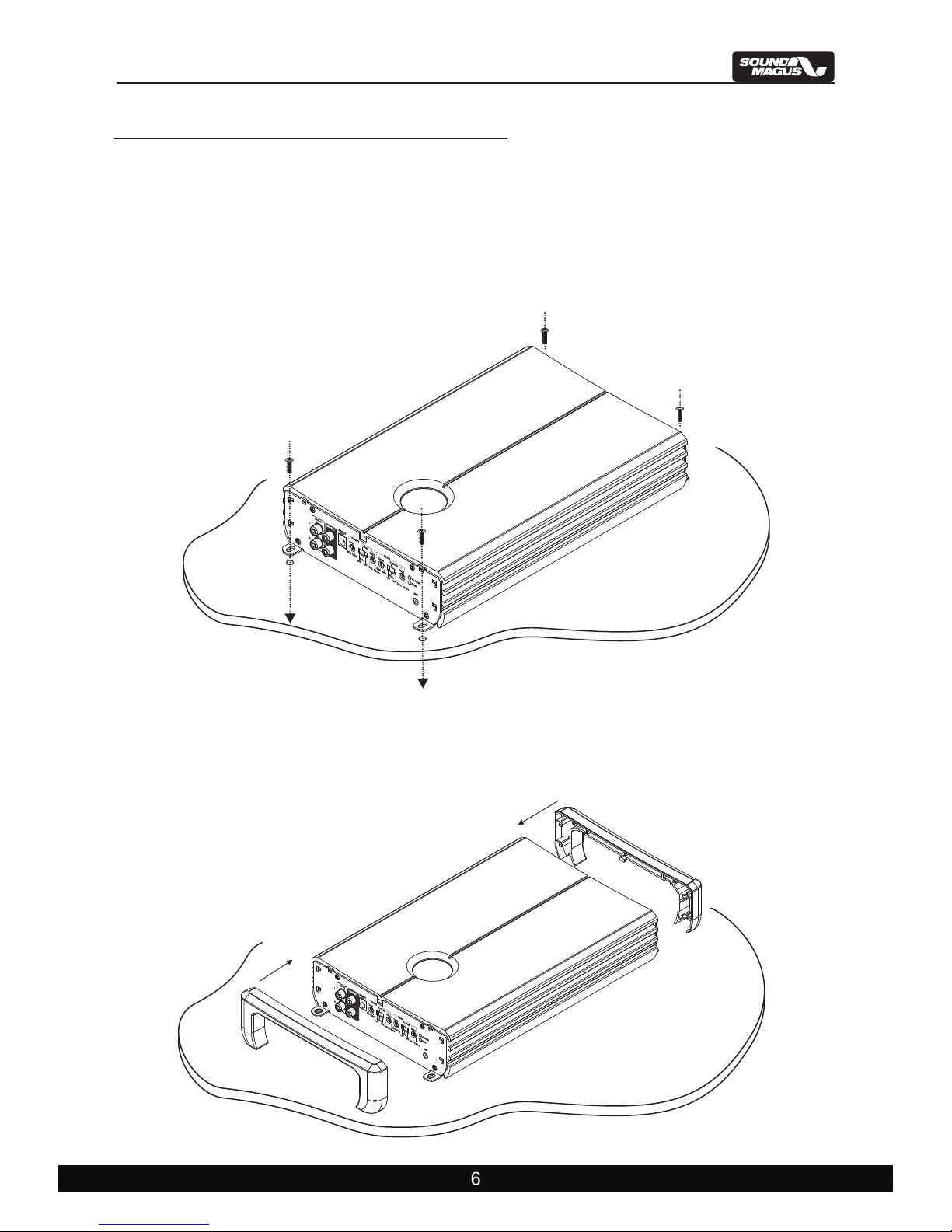
2 ) Using attached screws to fix the amplifier to the chosen place.
(As shown in Figure 1)
1 ) Choosing a flat and ventilated place to install amplifier.
1.Installation steps
Be sure to carefully read and understand the instructions before attempting to
install the Amplifier.
Figure 1 :
AMPLIFIERS INSTALLATION
3 ) Each plastic end cap has 5 buckles that match 5 buckle holes on the
amplifier. Hold two ends of the plastic end cap and push it towards the
amps horizontally.(As shown in Figure 2)
Figure 2 :
Horicontal push direction
Horicontal push direction
Table
Model
Cable
Fuse
ET90.4
40 A
ET150.4
4 - 6 #
60 A
4 - 8 #
11. RUN Indicator
This LED will light up when amplifier work properly. It will flash or shut
down once amplifier in self testing or malfunction.
12. Alarm Indicator
This LED will light up when amplifier detect a fault or shut down to
protect itself from permanent damage. This may caused by one of the
following: Excessive heat, reverse polarity, short circuit or overload. If this
happens please shut off the amplifier and check problem.
PREINSTALLATION
Please prepare sufficiently to layout your car space before installation. We
recommend to have the installation done by an Autho rized
SOUNDMAGUS Dealer.
Please use good insulated power cable to endure longterm above 40A
electronical current. The +12 Volt power cable must be connected with a
fuse in line near 20cm of battery+ terminal. Required current, power cable
and proper external fuse listed as following:
Please use car audio RCA cables, otherwise it may be disturbed. Keep
these cables as short as possible. To avoid disturbances from your car
electronics, please don`t close the existing car cables when you install
the RCA cables.
Don't expose any cables out of car. Please take care insulated cables to
avoid damaging when cables pass through metal, rubber and plastic etc.
Don't install all cables too tight.
The ground wire should be connected directly with the chassis of your
vehicle which should be metal to metal ground point onnection.
The amplifier must be mounted securely at a solid, dry and low vibration
surface in the trunk or passenger area. Fix the amplifier in an open air area
to insure proper heat dissipation.
2 ) Using attached screws to fix the amplifier to the chosen place.
(As shown in Figure 1)
1 ) Choosing a flat and ventilated place to install amplifier.
1.Installation steps
Be sure to carefully read and understand the instructions before attempting to
install the Amplifier.
Figure 1 :
AMPLIFIERS INSTALLATION
3 ) Each plastic end cap has 5 buckles that match 5 buckle holes on the
amplifier. Hold two ends of the plastic end cap and push it towards the
amps horizontally.(As shown in Figure 2)
Figure 2 :

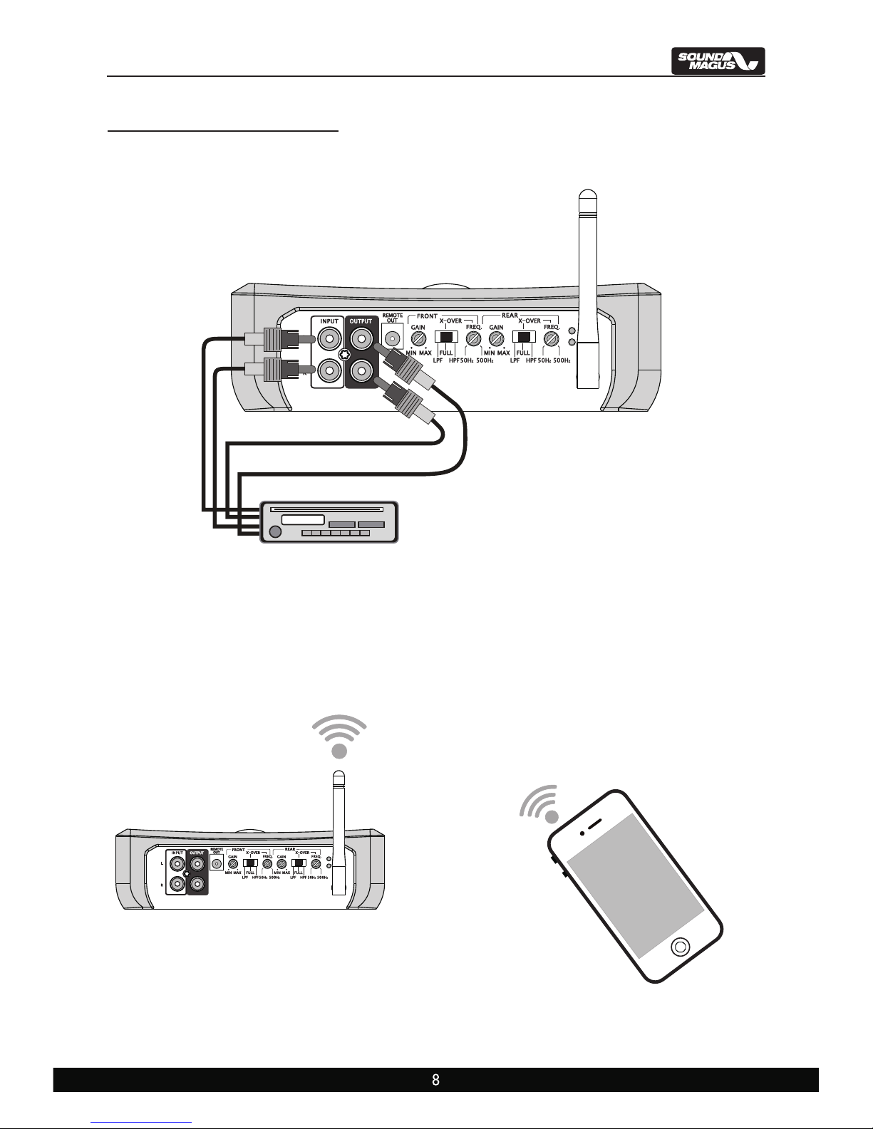
WIRING DIAGRAM
ET90.4/ET150.4 CD Connected Mode:
ET90.4/ET150.4 Bluetooth connection:
CD
5V Max Signal Input
CD
5 ) Plastic cap installation completed.
4 ) After The Plastic Cap Is Stick To The Amp, Holding Two Ends Of
The Plastic Caps(As Shown In Figure 3) And Push them down to
the same horizontal level ( As Shown In The Figure 3).
6 ) Antenna Installation Instructions。(As Shown In The Figure 4)
Figure 3:
7 ) Installation completed, now you can start the tuning and setting of
the amplifiers.
Clockwise screw to tighten
the antenna
Figure 4:
WIRING DIAGRAM
ET90.4/ET150.4 CD Connected Mode:
ET90.4/ET150.4 Bluetooth connection:
CD
5V Max Signal Input
CD
5 ) Plastic cap installation completed.
4 ) After The Plastic Cap Is Stick To The Amp, Holding Two Ends Of
The Plastic Caps(As Shown In Figure 3) And Push them down to
the same horizontal level ( As Shown In The Figure 3).
6 ) Antenna Installation Instructions。( As Shown In The Figure 4)
Figure 3:
7 ) Installation completed, now you can start the tuning and setting of
the amplifiers.
Clockwise screw to tighten
the antenna
Figure 4:
( )Example:ET90.4 and VS1500.1
REMOTE OUTPUT WIRING CONFIGURATION
CONNECTION OF BT AMPLIFIER AND MOBILE PHONE
Note: Amplifier can only connect to one mobilephone at a time. It doesn't
support multi connections.
(ET90.4/ET150.4)
(ET90.4/ET150.4)
OUTPUT WIRING CONFIGURATION
4Ohm 4 Channel configuration
Three Channel Model
Bridged 4Ohm woofer
Turn on the Bluetooth function on your mobile phone. Click "Search for
Bluetooth devices" and choose "SoundMagusBTAmp" from the list.
If there's System prompts for Bluetooth PIN code,enter " 0000".The
amplifier will be connected and paired with the mobilephone. The device
"SoundMagusBTAmp" will show "connected to the Media Audio”.
When the Amplifier is successfully connected to the mobile phone, the LED
indicator on top of the amplifier will enter into flashing status.

SPECIFICATIONS
Model ET150.4 ET90.4
RMS @ 4Ohm (Power supplier 14.4V) 135W x 4 80W x 4
160W x 4 120W x 4
320W x 2 230W x 2
Input Level 0.2~5V 0.2~5V
CH-A Filter Mode HP-FULL-LP
CH-B Filter Mode
CH-A LPF 50~500Hz
CH-A HPF
CH-B LPF
CH-B HPF
Frequency Response
THD at 4Ohm load 30% rated power <0.1% <0.1%
S/N Ratio >90dB >90dB
Channel Seperation >60dB >60dB
Minimum Load 2Ω
Overload Protect system YES
Overlead Protect system 80℃ / 176F 80℃ / 176F
Gold-plated isolation terminals YES
Componenets & PCB SMT&Double side board
Dimensions(x )mmLxW H 380 x 188 x 56 320 x 188 x 56
Remote Output YES YES
2.4G Antenna YES YES
HP-FULL-LP
50~500Hz
50~500Hz 50~500Hz
50~500Hz 50~500Hz
50~500Hz 50~500Hz
10~35KHz 10~35KHz
2Ω
YES
YES
Bluetooth transmission YES YES
RMS @ 2Ohm (Power supplier 14.4V)
RMS @ 4Ohm Bridged
(Power supplier 14.4V)
SMT&Double side board
HP-FULL-LP
HP-FULL-LP
11 12
TROUBLE SHOOTING
Symptom Possible Remedy
Amplifierwill
notpower up
Protection
LED Comes on
Check to make sure you have a good ground connection.
Check that there is battery power on the (+)terminal .
Check all fuses, replace if necessary .
Make sure that the Protection LED is not illuminated.
Check for short circuits on speaker leads.
Check the speaker load not beyond the minimum load.
Remove speaker lead, and reset the amplifier.
If the protection LED still Comes on, then the amplifier is faulty
and needs servicing .
No output
Check that the RCA audio cables are plugged into the proper inputs.
Check all speakers wiring.
Check the headunit output and the amplifier level setting.
Low output Reset the level Control.
Check the Crossover Control settings.
High hiss in
The speakers
Check the RCA cable is not shorted to power ground at amplifier side.
Check the amplifier grounding.
Distorted sound
Check that the Input level control is set to match the signal level of
the head unit. Always try to set the Input level as low as possible.
Check that all crossover frequencies are properly set.
Check for short circuits on the speaker leads.
Amplifier
getsVery hot
Check that the minimum load impedance for the amplifier model
is correct.
Check that there is good air circulation around the amplifier. In some
applications, It may be necessary to add an external cooling fan.
If your amplifier is still malfunction after checking trough the troubleshooting
section, Please contact our authorized SOUNDMAGUS dealer.
This manual suits for next models
1
Table of contents
Other Sound Magus Car Amplifier manuals


