Sound Sation ZEPHIRO 1500 LOW FOG User manual
Please read this manual carefully, and properly take care of it!
USER MANUAL
Leggete questo manuale e conservatelo per future consultazioni!
MANUALE utente
1500W LOW Fog Machine with DMX
and Wireless Control
ZEPHIRO
1500 LOW fog

Dear customer,
First of all thanks for purchasing a SOUNDSATION® product. Our mission is to satisfy
all possible needs of musical instrument, professional audio and lighting users offering
a wide range of products using the latest technologies.
We hope you will be satised with this item and, if you want to collaborate, we are
looking for a feedback from you about the operation of the product and possible im-
provements to introduce in the next future. Go to our website www.soundsationmusic.
com and send an e-mail with your opinion, this will help us to build instruments ever
closer to customer’s real requirements.
One last thing: read this manual before using the instrument, an incorrect operation
can cause damages to you and to the unit. Take care!
The SOUNDSATION Team
Gentile Cliente,
Grazie per aver scelto un prodotto SOUNDSATION®. La nostra missione è quella di
offrire ai nostri utenti una vasta gamma di strumenti musicali ed apparecchiature audio
e lighting con tecnologie di ultima generazione.
Speriamo di aver soddisfatto le vostre aspettative e, se voleste collaborare, saremmo
lieti di ricevere un vostro feedback sulla qualità del prodotto al ne di migliorare co-
stantemente la nostra produzione. Visitate il nostro sito www.soundsationmusic.com ed
inviateci una mail con la vostra opinione, questo ci aiuterà a sviluppare nuovi prodotti
quanto più vicini alle vostre esigenze.
Un’ultima cosa, leggete il presente manuale al ne di evitare danni alla persona ed al
prodotto, derivanti da un utilizzo non corretto.
Il Team SOUNDSATION

3
ENGLISH
TABLE OF CONTENTS
1. UNBOXING.................................................................................................................5
2. ACCESSORIES .............................................................................................................6
3. OVERVIEW..................................................................................................................6
4. REAR PANEL...............................................................................................................7
5. SETTING UP................................................................................................................7
6. MAINS CONNECTIONS .............................................................................................8
7. DMX CONNECTION...................................................................................................8
7.1. DMX Terminator .....................................................................................................................................................9
7.2. 3-Pin vs 5-Pin DMX cables .................................................................................................................................9
8. CONTROL MODE......................................................................................................10
9. NOTICES ..................................................................................................................10
10. ROUTINE MAINTENANCE AND COMMON FAULTS.............................................11
11. SPECIFICATIONS ......................................................................................................13
12. WARRANTY AND SERVICE .....................................................................................14
13. WARNING.................................................................................................................14

4
ENGLISH
IMPORTANT SAFETY SYMBOLS
The symbol is used to indicate that some hazardous live terminals are
involved within this apparatus, even under the normal operating condi-
tions, which may be sufcient to constitute the risk of electric shock or
death.
The symbol is used in the service documentation to indicate that spe-
cic component shall be replaced only by the component specied in
that documentation for safety reasons.
Protective grounding terminal
Alternating current/voltage
Hazardous live terminal
Denotes the apparatus is turned on
Denotes the apparatus is turned off
WARNING: Describes precautions that should be observed to prevent the danger
of injury or death to the operator.
CAUTION: Describes precautions that should be observed to prevent danger of
the apparatus.
TAKING CARE OF YOUR PRODUCT
fRead these instructions
fKeep these instructions
fHeed all warning
fFollow all instructions
Water / Moisture
The apparatus should be protected from moisture and rain and can not be used near
water; for example near a bathtub, a kitchen sink, a swimming pool, etc.
Heat
The apparatus should be located away from heat sources such as radiators,
stoves or other appliances that produce heat.
Ventilation
fAlways make sure that there is sufcient ventilation in the room. Fresh air needs to

5
ENGLISH
be able to enter the room and vaporized fog needs to be able to be drained from
the room.
fPay caution with the amount of fog used.
fThe use of fog is not hazardous for people or animals, if used with caution and
proper ventilation. Do not use more fog than needed to achieve the desired effect.
Object and Liquid Entry
Objects do not fall into and liquids are not spilled into the inside of the apparatus for
safety.
Power Cord and Plug
Protect the power cord from being walked on or pinched particularly at plugs, conve-
nience receptacles, and the point where they exit from the apparatus. Do not defeat
the safety purpose of the polarized or grounding-type plug. A polarized plug has two
poles; a grounding-type plug has two poles and a third grounding terminal. The third
prong is provided for your safety. If the provided plug does not t into your outlet, refer
to an electrician for replacement.
Fuse
fMain fuse of this device is to be found on rear panel, close to the power inlet.
fOnly replace fuse with a new one of the same type and rating! Do not use fuses
with a higher or lower rating
fDo not bridge fuse with electrical wires, aluminum foil, as it is used to protect
against electrical shocks and short circuit.
fAlways mount fuse cover back to the fuse compartment.
Electrical Connection
Improper electrical wiring may invalidate the product warranty.
Cleaning
Clean only with a dry cloth. Do not use any solvents such as benzene or alcohol.
Servicing
Do not implement any servicing other than those means described in the manual. Refer
all servicing to qualied service personnel only. Only use accessories/attachments or
parts recommended by the manufacturer.
1. UNBOXING
When receiving the machine, open its package and check carefully whether the ma-
chine is damaged or accessories are lost, if any problems, please contact the supplier.
When you’ll open the package (1 carton) you will nd the following items:
f1x Low Fog Machine
f1x Power Cord

6
ENGLISH
f1x Remote Controller
fThis User Manual
WARNING: Packaging bag is not a toy! Keep out of reach of children!!! Keep
in a safe place the original packaging material for future use.
2. ACCESSORIES
SOUNDSATION can supply a wide range of quality accessories that you can use with
your ZEPHIRO Ambience Effects Series, like Cables, DMX Controllers, Liquids, etc.
All products in our catalogue has been long tested with this device so we recommend
to use Genuine SOUNDSATION Accessories and Spare Parts.
Ask your SOUNDSATION dealer for any accessories you could need to ensure best
performance of the product.
3. OVERVIEW
ZEPHIRO 1500 LOW FOG is a powerful 1500 Watt fog machine designed to produce
a ground fog effect to enhance dance oors, stages, entry ways etc. This machine is
equipped with a DMX interface and, moreover, it can also be used with a small radio
control which, thanks to the built-in reception card, allows the use of the machine with-
out connecting cables.
ZEPHIRO 1500 LOW FOG is able to generate a fog volume of 283 m³/min and cover an
area of 60 m² thanks to a 1500 watt heating system, a powerful pump and a large tank
(2,3L).

7
ENGLISH
ZEPHIRO 1500 LOW fog User manual
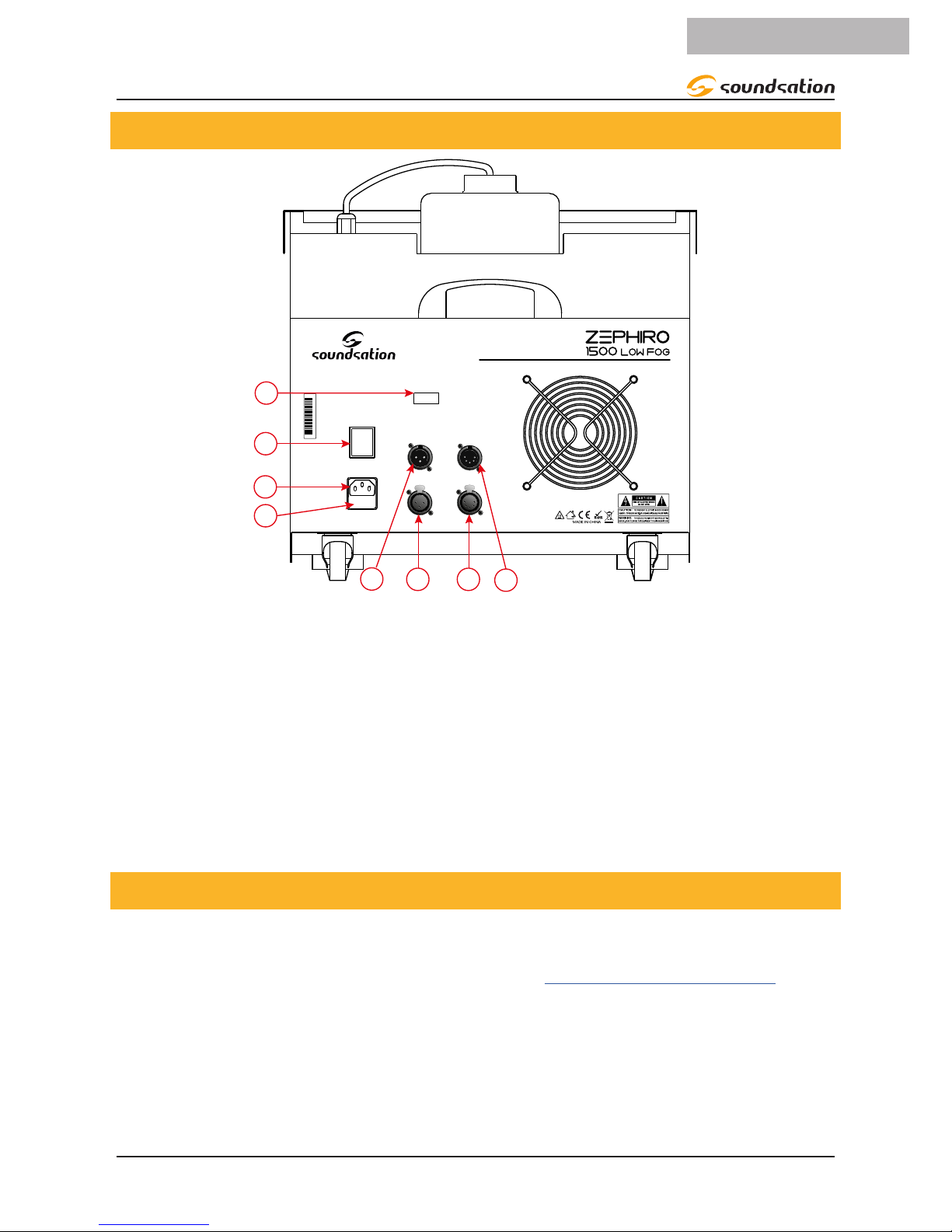
4. REAR PANEL
1
2
3
ON
1500W LOW Fog Machine with DMX and Wireless Control
OFF
IN
OUT
POWER
230Vac-50Hz
Fuse F10A-250V
DMX CH SETUP
1
2
4
6
8
16
32
64
128
256
0725301018010001
IN
OUT
DMX512
3-Pin
DMX512
5-Pin
45 6 7
8
1. On/off switch
2. Power inlet (IEC connector)
3. Fuse
4. DMX 3-Pin XLR Input
5. DMX 3-Pin XLR Output
6. DMX 5-Pin XLR Output
7. DMX 5-Pin XLR Input
8. DMX dip-switch panel
5. SETTING UP
fKeep the fog machine in horizontal position, do not tilt or ip. Before connecting
this unit to mains, ll in the tank with uid. Always use water-based fog uid (check
www.soundsationmusic.com for further information) and check that nozzle is clean
and unobstructed.
fPut some ice blocks into the machine ice storage (It is better to use crushed ice)
fBefore connecting to power, check whether mains voltage is suitable for the unit or
not.
8
ENGLISH
ZEPHIRO 1500 LOW fog User manual
fThe power cord must be connected to a grounded electric outlet. Once connected,
turn ON the machine with the corresponding switch and then the heating process
will start which will last about 4 minutes. After that the fog machine is ready to use.
fUse the supplied remote control to control the machine.
6. MAINS CONNECTIONS
Connect the device to the mains with the supplied power cable. Please note that power
voltage and frequency are the same as the marked voltage and frequency of device
when connecting power.
Wire correspondence is as follow:
Cable (EU) Pin International
Brown Live L
Blue Neutral N
Yellow/Green Earth
The earth must to be connected! Pay attention to safety! Before taking into
operation for the rst time, the installation has to be approved by an expert.
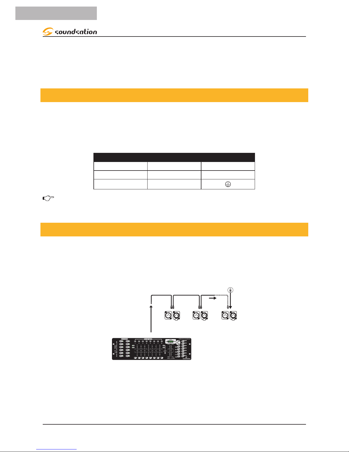
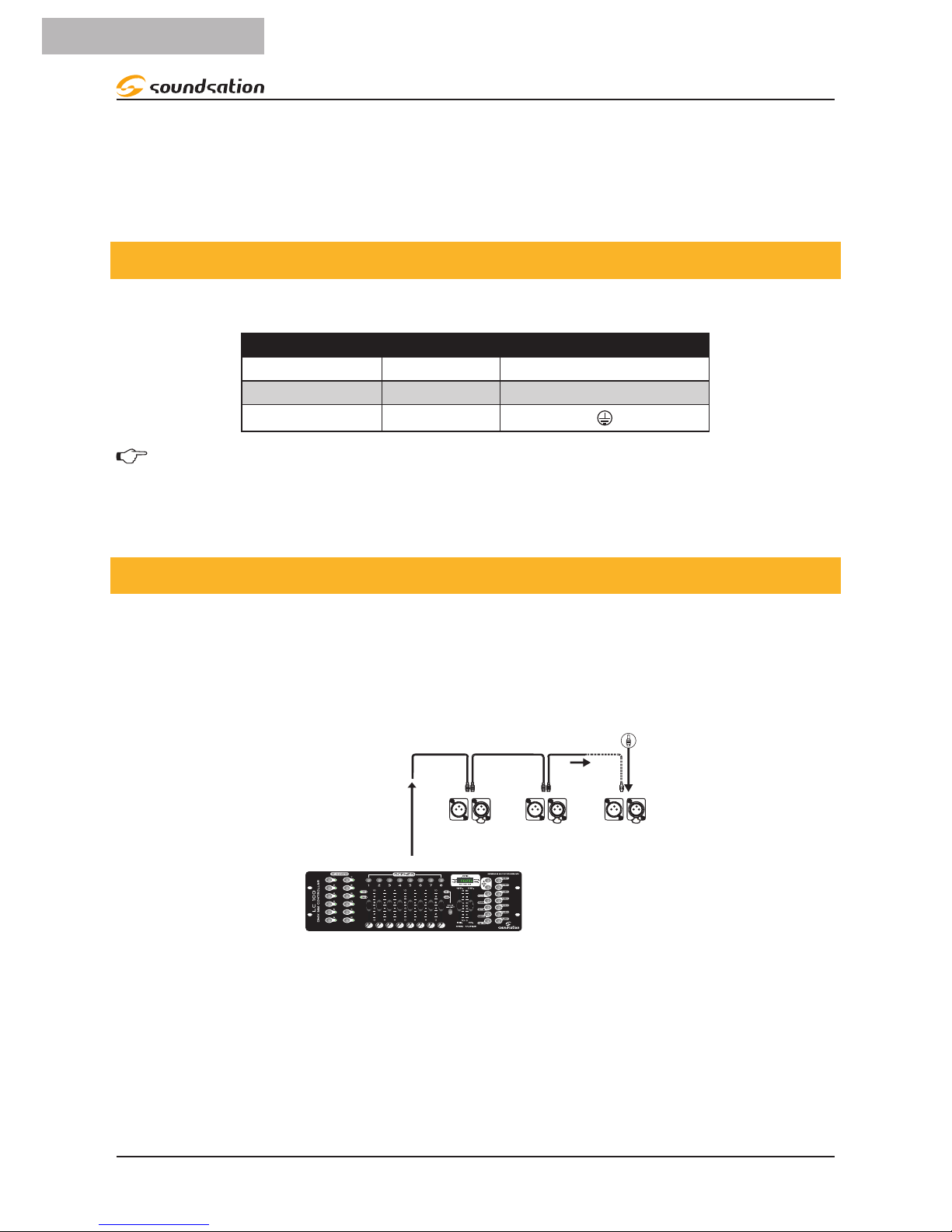
7. DMX CONNECTION
DMX xtures are designed to receive data through a serial Daisy Chain. A Daisy Chain
connection is where the DATA OUT of one xture connects to the DATA IN of the next
xture. The order in which the xtures are connected is not important and has no effect
on how a controller communicates to each xture. Use an order that provides for the
easiest and most direct cabling.
DMX Termonator
Unit 1 Unit 2 Last Unit
DMX 512
Connect xtures using shielded 2-conductor twisted pair cable with 3-pin XLR male to
female connectors. The shield connection is pin 1, while pin 2 is Data Negative (S-), and
pin 3 is Data positive (S+).

9
ENGLISH
ZEPHIRO 1500 LOW fog User manual
3-Pin XLR
Pin 1: GND
Pin 2: DMX -
Pin 3: DMX +
OUTPUTINPUT
DMX use of 3-Pin XLR Connectors
CAUTION: Wires must not come into contact with each other; otherwise the
xtures will not work at all, or will not work properly.
7.1. DMX Terminator
DMX is a resilient communication protocol, however errors still occasionally occur.
In order to prevent electrical noise from disturbing and corrupting the DMX control
signals, a good habit is to connect DMX output of last xture in the chain to a DMX
terminator, especially over long signal cable runs.
120ohm, 1/4
W
resistor
DMX Terminator
The DMX terminator is simply an XLR connector with a 120Ω (ohm), 1/4 Watt resistor
connected across Signal (-) and Signal (+), respectively, pins 2 and 3, which is then
plugged into the output socket on last projector in the chain. The connections are
illustrated below.
Complimentary signal cable can transmits signals to 20 unit xtures at most.
Signal amplier is a must to connect more xtures.
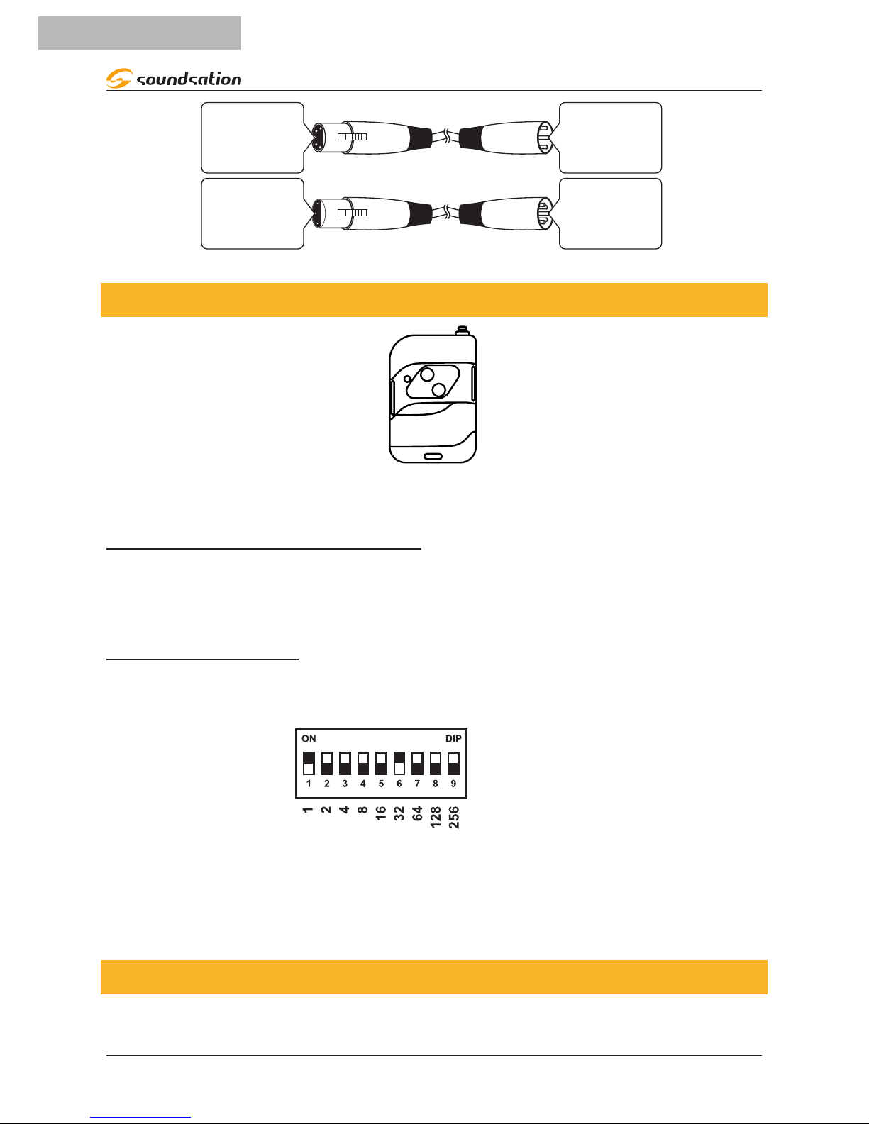
7.2. 3-Pin vs 5-Pin DMX cables
DMX connection protocols used by controllers and xtures manufacturers are not stan-
dardized around the world. However, two are the most common standards: 5-Pin XLR
and 3-Pin XLR system. If you wish to connect the unit to a 5-Pin XLR input xture, you
need to use an adapter-cable or make it by yourself.
Following the wiring correspondence between 3-Pin and 5-Pin plug and socket stan-
dards.
10
ENGLISH
ZEPHIRO 1500 LOW fog User manual
5-Pins XLR (plug)
Pin 1: GND (Screen)
Pin 2: Signal (-)
Pin 3: Signal (+)
Pin 4: N/C
Pin 5: N/C
3-Pins XLR (socket)
Pin 1: GND (Screen)
Pin 2: Signal (-)
Pin 3: Signal (+)
5-Pins XLR (socket)
Pin 1: GND (Screen)
Pin 2: Signal (-)
Pin 3: Signal (+)
Pin 4: N/C
Pin 5: N/C
3-Pins XLR (plug)
Pin 1: GND (Screen)
Pin 2: Signal (-)
Pin 3: Signal (+)
8. CONTROL MODE
A
B
WIRELESS CONTROLLER
Wireless remote control
Once warm-up process is complete, press A or B button to emit fog. By pressing them
long time, you can spray fog long time till the unit will warm up again. By releasing
buttons, it stops spraying fog.
DMX512 Control
One DMX Channel is used to control fog emission. This channel is selectable through
the DMX Dip-switch panel.
Switch value
Switch number
Final value is obtained by adding values of all switches in ON position. This way, you
are able to make combinations to reach the desired DMX value between 1 and 512. For
example, if you wish to set the device to channel 33, you need to select dip-switch 1
and 6 (1 + 32 = 33).
9. NOTICES
fThis fog machine should be used in dry and well-ventilated place . Please avoid any
water or rain fall in the machines, if water and rain fall in, turn off the power imme-

11
ENGLISH
ZEPHIRO 1500 LOW fog User manual
diately. The room for cooling should be at least 30cm. Keep far away from children,
re, explosive and ammable things, and avoid scalding.
fIn the rst time use, some water might spray out. This is normal.
fWhen liquid is getting low, please add it again in time. If the fog machine works
without uid for a long time, its pump and other parts could get damaged. When
adding uid, remember to turn power off, and carefully avoid spilling over to cause
short circuits.
fThe fog machine should work under professional operator’s supervision, please do
not add ammable liquids, gas or perfume into the fog uid tank.
fWhen working, do not touch the machine and power cord.
fWhen you don’t use the machine for long time or after use, please disconnect
power or unplug the power cord.
fAfter using, please wipe out the liquid in the tank, as it would avoid the housing to
be corroded.
fAfter use, drain the water from the machine’s icebox using the special tap.
fAll fog machines will have condensation or moisture around the nozzle.
fAll fog machines are used to emit a small amount of smoke during or after use.
fAll fog machines have heating-cooling cycles. When internal temperature drops to
minimum, the pump automatically turns on and begins heating. Once heating is
complete, the machine starts to spray smoke again.
All fog machines may set off Smoke Alarms
10. ROUTINE MAINTENANCE AND COMMON FAULTS
Periodically clean your machine to reduce replacement parts and repair ex-
penses.
fPoor fog liquid can cause blockage. It is recommended to use high quality fog
liquid.
fThe machine might get blocked due to high concentration uid, not-pure uid or
overheat, so regular care and maintenance can ensure long-term use. After about
40 hours continue use, please prepare an 80% distilled water and 20% white vine-
gar blend to remove any accumulated impurities inside boiler and pipe, as follow-
ing:
1. Wash the pipe in the tank and its lter head.
2. Pour out any liquid inside, and replace with the cleaning liquid (80% distilled
water and 20% white vinegar), turn on power, keep it operating till the clean-
ing liquid runs out.
fIf the fog turns less, and the pump makes noise, switch off the unit immediately
and check uid level, fuse, controller interface and power plug. If all of these are
normal, please connect power again. If problems still continue, please contact the

12
ENGLISH
ZEPHIRO 1500 LOW fog User manual
supplier.
fWhen you shut down the machine, it is recommended that you remove any re-
maining uid inside. Especially when the machine will not be used for a long time.
It is recommended that you open the tank, remove the uid hose and place it next
to the tank in open air.
fAfter use, let the fog machine cool down before transporting it by the handle.
Small bits of fog may still be emitted just after the machine is switched off. Let the
machine cool down for at least 20 minutes and only transport it when the housing
of the machine reaches a temperature that is comfortable enough to handle. Trans-
porting the machine while it is still hot may cause injuries and permanent damage
to the internal electronics and heating elements.

13
ENGLISH
ZEPHIRO 1500 LOW fog User manual
11. SPECIFICATIONS
Heating element 1500 Watt
Warm-up time 4 Minutes
Tank capacity 2,3 Liters
Fog output 283m³ per minute
Coverage Area 60m²
Wireless remote controller included Yes - 433.92 MHz (Max 10 Meters)
DMX control Yes (One Channel)
Power requirements 220V AC, 50Hz
Internal fuse 10A 250V fast blow 20mm glass
Dimensions 765 x 395 x 415 mm
Weight 17,4 Kg
Packing Size 840 x 500 x 480 mm
Packing Weight 18,8 Kg
14
ENGLISH
ZEPHIRO 1500 LOW fog User manual
12.WARRANTY AND SERVICE
All SOUNDSATION products feature a limited two-year warranty. This two-year warranty is specic
to the date of purchase as shown on your purchase receipt.
The following cases/components are not covered from the above warranty:
• Any accessories supplied with the product
• Improper use
• Fault due to wear and tear
• Any modication of the product effected by the user or a third party
SOUNDSATION shall satisfy the warranty obligations by remedying any material or manufacturing
faults free of charge at our discretion either by repair or by exchanging individual parts or the en-
tire appliance. Any defective parts removed from a product during the course of a warranty claim
shall become the property of SOUNDSATION.
While under warranty period, defective products may be returned to your local SOUNDSATION
dealer together with original proof of purchase. To avoid any damages in transit, please use the
original packaging if available. Alternatively you can send the product to SOUNDSATION SERVICE
CENTER – Via Enzo Ferrari , 10 – 62017 Porto Recanati - Italy . In order to send a product to service
center you need an RMA number. Shipping charges have to be covered by the owner of the prod-
uct.
For further information please visit www.soundsationmusic.com
13.WARNING
PLEASE READ CAREFULLY – EU and EEA (Norway, Iceland and Liechtenstein) only
This symbol indicates that this product is not to be disposed of with your household waste, ac-
cording to the WEEE Directive (2202/96/EC) and your national law.
This product should be handed over to a designated collection point, e.g., on an authorized one-
for-one basis when you buy a new similar product or to an authorized collection site for recycling
waste electrical and electronic equipment (WEEE).
Improper handling of this type of waste could have a possible negative impact on the environment
and human health due to potentially hazardous substances that are generally associated with
WEEE. At the same time, your cooperation in the correct disposal of this product will contribute to
the effective usage of natural resources.
For more information about where you can drop off your waste equipment for recycling, please
contact your local city ofce, waste authority, approved WEEE scheme or your household waste
disposal service.

SOMMARIO
14. DISIMBALLAGGIO ...................................................................................................18
15. ACCESSORI ...............................................................................................................18
16. PANORAMICA..........................................................................................................18
17. PANNELLO POSTERIORE.........................................................................................19
18. SETTAGGIO...............................................................................................................19
19. CONNESSIONI DI RETE ...........................................................................................20
20. CONNESSIONI DMX ................................................................................................20
20.1. Terminatore DMX.................................................................................................................................................21
20.2. Cavi DMX 3-Poli / 5-Poli....................................................................................................................................21
21. MODALITÀ DI CONTROLLO....................................................................................22
22. AVVISI .......................................................................................................................22
23. MANUTENZIONE ORDINARIA E GUASTI COMUNI..............................................23
24. SPECIFICHE...............................................................................................................25
25. GARANZIA ED ASSISTENZA...................................................................................26
26. AVVERTENZA ...........................................................................................................26
15
ITALIANO

IMPORTANTI ISTRUZIONI DI SICUREZZA
Il simbolo è usato per indicare che in questa apparecchiatura sono
presenti alcuni terminali sotto tensione pericolosi, anche in condizioni
di normale funzionamento, che possono costituire rischio di scosse
elettriche o di morte.
Il simbolo viene utilizzato nella documentazione di servizio per indi-
care che uno specico componente può essere sostituito esclusiva-
mente dal componente specicato nella documentazione per motivi di
sicurezza.
Terminale di Terra
Corrente/Tensione alternata
Terminale in tensione pericoloso
Indica che l’apparato è acceso
Indica che l’apparato è spento
WARNING: Precauzioni da osservare per evitare il pericolo di ferimento o di morte
per l’utilizzatore.
CAUTION: Precauzioni da osservare per evitare danni all’apparecchio.
CURA DEL PRODOTTO
fLeggete queste istruzioni
fConservate queste istruzioni
fRispettate tutte le avvertenze
fSeguite tutte le istruzioni
ACQUA / UMIDITA
L’apparecchio deve essere protetto dall’umidità e dalla pioggia, non può essere usato
in prossimità di acqua; ad esempio nei pressi di una vasca da bagno, di un lavandino, di
una piscina, etc.
Calore
L’apparecchio deve essere posto lontano da fonti di calore come radiatori,
stufe o altri apparecchi che producono calore.
16
ITALIANO
Manuale d’uso ZEPHIRO 1500 LOW FOG

.Ventilazione
fAssicurarsi sempre che ci sia una sufciente ventilazione in modo che l’aria possa
circolare e la nebbia vaporizzata possa essere scaricata dalla stanza di utilizzo del
dispositivo.
fPrestare attenzione alla quantità di nebbia utilizzata.
fL’uso della nebbia non è pericoloso per le persone o gli animali, se usato con cau-
tela e adeguata ventilazione. Non utilizzare più nebbia del necessario per ottenere
l’effetto desiderato.
Introduzione di oggetti e liquidi
Non introdurre oggetti o versare liquidi all’interno dell’apparato per ragioni di sicurezza.
CAVO DI RETE
Proteggere il cavo di alimentazione per evitare che venga calpestato o schiacciato, in
particolare in corrispondenza delle spine, prese e il punto di uscita dall’apparecchio.
Non annullare l’obiettivo di sicurezza della spina polarizzata o con messa a terra. Una
spina polarizzata ha due poli; una spina di messa a terra presenta due poli ed un terzo
terminale di terra. Il terzo polo è previsto per la vostra sicurezza. Se la spina fornita non
entra nella presa, consultare un elettricista per la sostituzione.
Fusibile
fIl fusibile principale di questo dispositivo si trova sul pannello posteriore, vicino alla
presa dell’alimentazione.
fSostituire il fusibile esclusivamente con uno nuovo dello stesso tipo e valore. Non
utilizzare fusibili di valore superiore o inferiore.
fNon collegare il fusibile con cavi elettrici, fogli di alluminio, poiché è usato per
proteggere da scosse elettriche e cortocircuiti.
fRimontare sempre correttamente il coperchio del fusibile nello scomparto del
fusibile.
Collegamento alla rete elettrica
L’apparecchio deve essere collegato alla sorgente di alimentazione elettrica del tipo
indicato sull’apparecchio o descritto nel manuale.
Un collegamento elettrico non corretto può invalidare la garanzia del prodotto.
Pulizia
Pulire solo con un panno asciutto. Non utilizzare solventi come benzene o alcool.
Manutenzione
In caso di guasto o malfunzionamento, interrompere immediatamente l’unità. Non ef-
fettuate qualsiasi altro intervento al di fuori di quelli descritti nel manuale. Per eventua-
le assistenza rivolgetevi solo a personale qualicato. Utilizzate solo accessori / compo-
nenti suggeriti dal produttore.
17
ITALIANO
Manuale d’uso Zephiro 1500 LOW FOG

14.DISIMBALLAGGIO
Quando si riceve la macchina, aprire la confezione (1 scatola), controllare attentamente
che non sia danneggiata e che gli accessori non siano andati persi. In caso di problemi,
contattare il fornitore. All’apertura del pacco, si troveranno i seguenti articoli.
f1x Macchina del fumo
f1x Cavo di alimentazione
f1x Radiocomando
fQuesto Manuale Utente
ATTENZIONE: L’imballo non è un giocattolo! Tenere fuori dalla portata dei
bambini!!! Conservare in un luogo sicuro il materiale di imballaggio originale
per un utilizzo futuro.
15.ACCESSORI
SOUNDSATION in grado di fornire una vasta gamma di accessori di qualità che è
possibile utilizzare in tutti i dispositivi della serie ZEPHIRO, come cavi DMX, console di
illuminazione, liquidi e altri accessori. Tutti i prodotti del catalogo SOUNDSATION sono
stati a lungo testati con questo dispositivo quindi si consiglia di utilizzare accessori
originali e parti di ricambio Soundsation. Chiedete al vostro rivenditore SOUNDSATION
per gli accessori il necessario per garantire le migliori prestazioni del prodotto.
16.PANORAMICA
ZEPHIRO 1500 LOW FOG è una potente macchina da nebbia da 1500 Watt progettata per
produrre un effetto nebbia a terra per esaltare piste da ballo, palcoscenici, ingressi ecc.
Questa macchina è dotata di un’interfaccia DMX e, inoltre, può essere utilizzata anche
con un piccola radiocomando che, grazie alla scheda di ricezione integrata, consente
l’utilizzo della macchina senza cavi di collegamento.
ZEPHIRO 1500 LOW FOG è in grado di generare un volume di nebbia di 283 m³ / min e
coprire un’area di 60 m² grazie ad un sistema di riscaldamento da 1500 watt, una potente
pompa e un grande serbatoio (2,3L).
18
ITALIANO
Manuale d’uso ZEPHIRO 1500 LOW FOG
17. PANNELLO POSTERIORE
1
2
3
ON
1500W LOW Fog Machine with DMX and Wireless Control
OFF
IN
OUT
POWER
230Vac-50Hz
Fuse F10A-250V
DMX CH SETUP
1
2
4
6
8
16
32
64
128
256
0725301018010001
IN
OUT
DMX512
3-Pin
DMX512
5-Pin
45 6 7
8
1. Interruttore On/off
2. Ingresso di Alimentazione (Connettore IEC )
3. Fusibile
4. Ingresso DMX con 3-Poli di tipo XLR
5. Uscita DMX con 3-Poli di tipo XLR
6. Uscita DMX con 5-Poli di tipo XLR
7. Ingresso DMX con 5-Poli di tipo XLR
8. Pannello di selezione del canale DMX
18.SETTAGGIO
fTenere il dispositivo in posizione orizzontale, non inclinare o capovolgere. Prima di
collegare questa unità alla rete, riempire il serbatoio con il uido. Utilizzare sempre
il uido nebulizzato a base di acqua (consultare www.soundsationmusic.com per
ulteriori informazioni) e controllare che l’ugello sia pulito e non ostruito.
fMettere del ghiaccio nella ghiacciaia della macchina (è meglio usare il ghiaccio
tritato).
fPrima di collegare l’alimentazione, vericare se la tensione di rete è adatta all’unità
o meno.
fIl cavo di alimentazione deve essere collegato a una presa elettrica con messa a
19
ITALIANO
Manuale d’uso Zephiro 1500 LOW FOG
terra. Una volta collegato, accendi la macchina con l’interruttore corrispondente e
inizierà il processo di riscaldamento che durerà circa 4 minuti dopo di che la mac-
china del fumo sarà pronta per l’uso.
fServirsi del radiocomando in dotazione per utilizzare la macchina.
19.CONNESSIONI DI RETE
Collegare il dispositivo alla presa con la spina. La corrispondenza dei cavi è la seguente:
CAVO PIEDINO INTERNAZIONALE
Marrone Fase L
Blu Neutro N
Giallo/verde Terra
La messa a terra deve essere collegata! Prestare attenzione alla sicurezza!
Prima di metter in funzione l’apparecchio per la prima volta, l’installazione deve essere
approvata da un esperto.
20. CONNESSIONI DMX
Gli apparecchi DMX sono progettati per ricevere dati attraverso una catena seriale a
cascata. Questo tipo di connessione permette di connettere il DATA OUT di un dispo-
sitivo al DATA IN del dispositivo successivo. L’ordine in cui i dispositivi sono collegati
non è importante e non ha alcun effetto su come un controllore comunica a ciascuna
apparecchiatura. Utilizzare un ordine che preveda il cablaggio più semplice e diretto.
DMX Termonator
Unit 1 Unit 2 Last Unit
DMX 512
Collegare i dispositivi utilizzando un cavo bipolare schermato a 2 conduttori con
connettori XLR maschio-femmina a 3 poli. La connessione dello schermo è il piedino 1,
mentre il piedino 2 è negativo (S-)e il piedino 3 è positivo (S +).
20
ITALIANO
Manuale d’uso ZEPHIRO 1500 LOW FOG
Table of contents
Languages:
Other Sound Sation Fog Machine manuals


