www.soundskulptor.com
Document revision 1.1 – Last modification : 16/03/13
MP .12 Test guide
Follow the testing procedure in the shown order. If one test fails, find out the problem, correct it then resume.
Always unplug power between steps because it is very easy to create a shortcut when moving a DMM probe. And most
of the time, shortcuts are fatal to the circuits.
Step Description
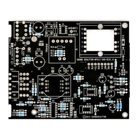
1. Test setup Remove the 2 jumpers on JMP3.
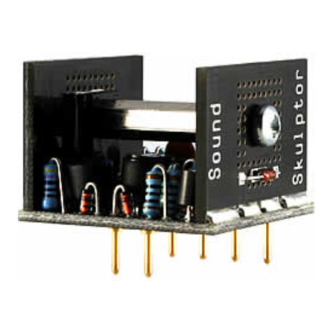
Remove the DOA.
Remove the Di01 board if present and make a connection
on CN1 between the last 2 pins, near the board edge, with
a small piece of wire (a cut resistor leg will do nicely).
2. Short circuit check Do a basic short circuit check with your digital multimeter (DMM) set to Ohms :
•Between Test points GND and V+.
•Between Test points GND and V-.
In both cases you should get several kilo-Ohms. If it is not the case, find out and fix the
short before applying power.
3. Board installation Plug the MP 12 into your 00 connector Extender , if you own one or...
Remove all other modules from you 00 rack or Lunchbox and insert the MP 12 in the
leftmost slot.
4. General power check Plug in power and check that the LEDs on the power supply unit are lighting normally. If
one or more LED is staying off or is lighting too low or too bright, immediately plug off
power and start checking your board.
. Positive rail check Set your DMM to DC Volts on a 30 V scale and connect it between GND and V+. Use
test hooks and be careful not to create shortcuts.
Check that you get a positive voltage around +16V.
6. Negative rail check Connect your DMM between GND and V-.
Check that you get a negative voltage around -16V.
7. Voltage setup with
charge
Plug off power.
Insert the DOA.
Plug in power. Check both voltages again.
Insert the 2 jumpers on JMP3.
Check both voltages again.
Copyright ©2013 SoundSkulptor
