www.soundskulptor.com
Document revision 1.1 – Last modification : 14/08/10
Step Description
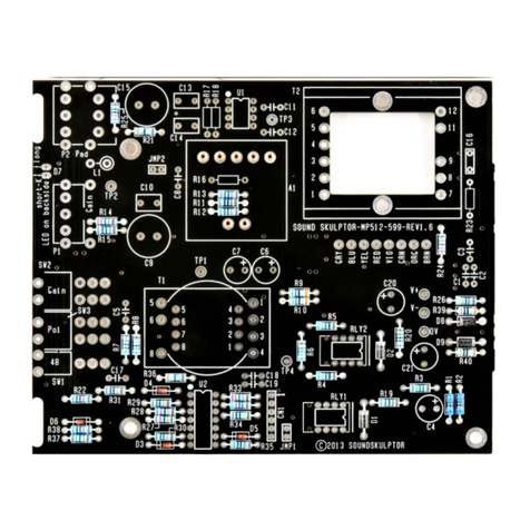
4. Bias adjust With P2, we are going to adjust the bias of Q6 in order to flow about 6 mA of direct
current in the output transformer primary. To do this, we are going to measure the
voltage across resistor R39, between TP2 and TP3.
Set your DMM to DC volts.
Place the (+) probe of your DMM on the test pin TP2. Place the (-) probe of your DMM
on the test pin TP3.
Adjust P2 until you read 3.0 Volts on the DMM. P2 is a multi-turn so it may take several
turns to see a change.
Warning : If you do not see any voltage change when turning P2, stop adjusting and check
your board. You probably have a wiring error.
Warning : Turning P2 clockwise increases the current in Q6. If you turn it too far, the
current will reach a value that might smoke R39 !
. Sound check Plug in a dynamic microphone to the input XLR.
Connect the output to your monitoring system. It can be a headphone amplifier or it can
go through one of your ADC inputs if you run a software studio.
Set Gain switch to 10dB, “Trim” knob to center, 48V to Off.
Plug in power.
Turn the gain switch until you hear that your mic pre is working. Check all the positions of
the gain switch, the “Trim” pot and the Phase switch.
Verify that the green LED lights up when a sound is playing and that it turns red when it
come near saturation.
Make the same test with a condenser microphone, with the 48V switch set to On.
Plug off power.
Set the 48V switch to Off.
6. DI check Remove the wire jumper we made in step 2 and install the Di01 board.
Insert an instrument jack into the front panel jack socket.
Plug in power.
You should hear your instrument when playing.
Plug off power.
7. Congratulations Done !
Copyright ©2010 SoundSkulptor
