Sound Skulptor PSL1 User manual
www.soundskulptor.com
Document revision 1.1 – Last modification : 21/04/08
P L1 Assembly guide
afety warning
THI KIT I NOT FOR BEGINNER !
This kit is main powered and use potentially lethal voltages. Under no circumstance should someone undertake the
realisation of this kit unless he has full knowledge about safely handling main powered devices.
Please read the “DIY guide” before beginning.
Print or open the following documents :
•P L1 chematic
•P L1 Components layout
•P L1 Parts list
•P L1 etup guide
Follow this guide from item number 1 till the end, in this order. The assembly order is based on components height, from
low to high profile, in order to ease the soldering process : The component you are soldering is always taller than the
previously assembled ones and it is pressing nicely against the work area foam.
P L1 Assembly guide
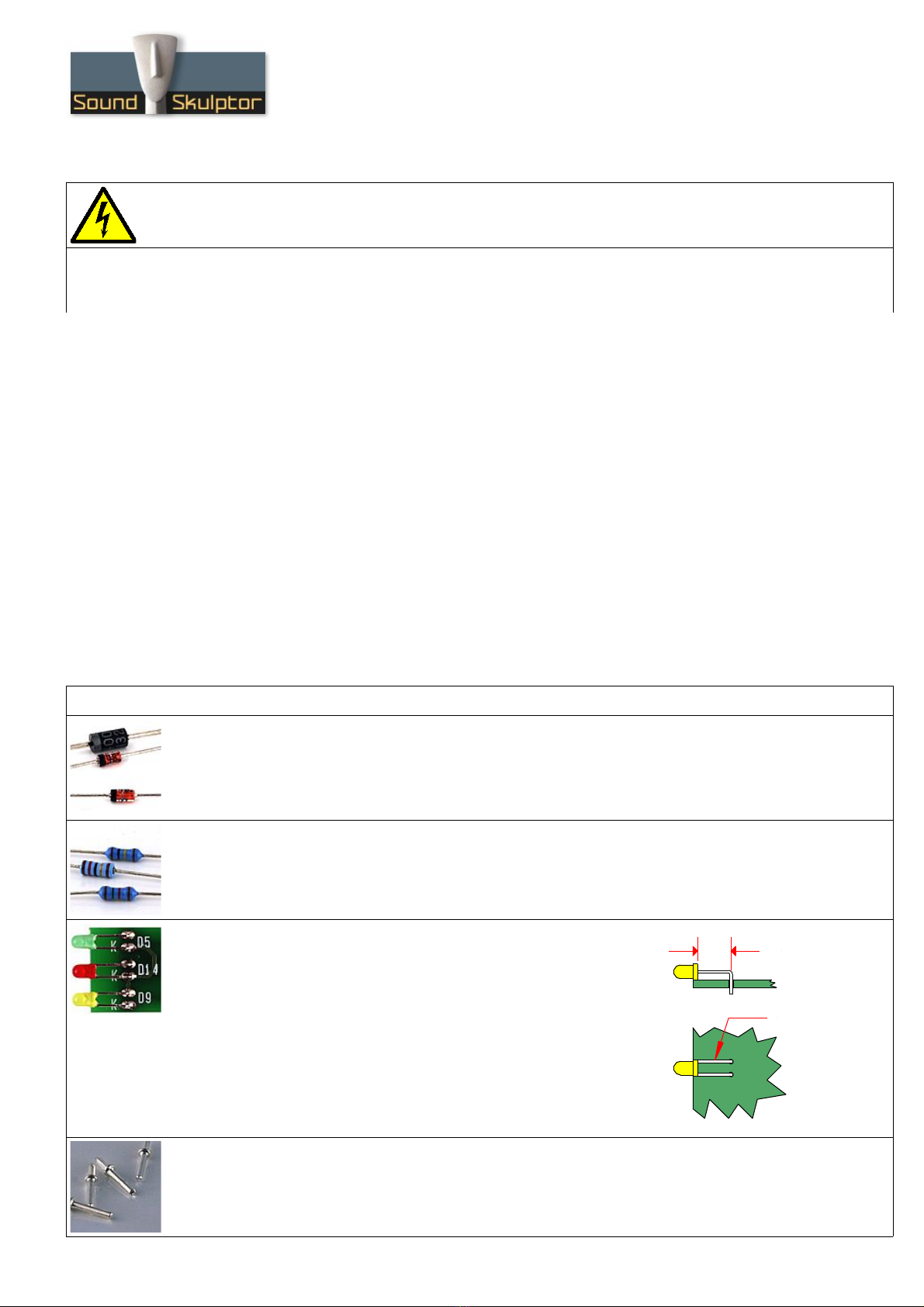
1. Diodes
Add D1 to D4, D6 to D8, D10 to D13. Use a lead forming tool to cleanly bend the leads at 0.4”
except for D11 which is bent at 0,5".
Warning : Make sure to respect the direction of the diodes which is marked by a ring on the component
and a double line on the PCB marking.
2. Resistors
Add R1 to R9. Control the resistor values with a digital multimeter. Bend the leads at 0.4” with a lead
forming tool.
3. Leds
Add D5, D9, D14.
Bend the leads at 7mm from the body taking care of the anode position
(the longest lead).
Warning : it is easy to bend the leads in the wrong direction !
older the LED so it rests on the board. tart by soldering one lead,
adjust the position, then solder the second lead.
4. Test pins
older the 4 test pins TP1 to TP4.
Copyright ©2008 ound kulptor
7.00 mm
Anode : long lead
www.soundskulptor.com
Document revision 1.1 – Last modification : 21/04/08
P L1 Assembly guide
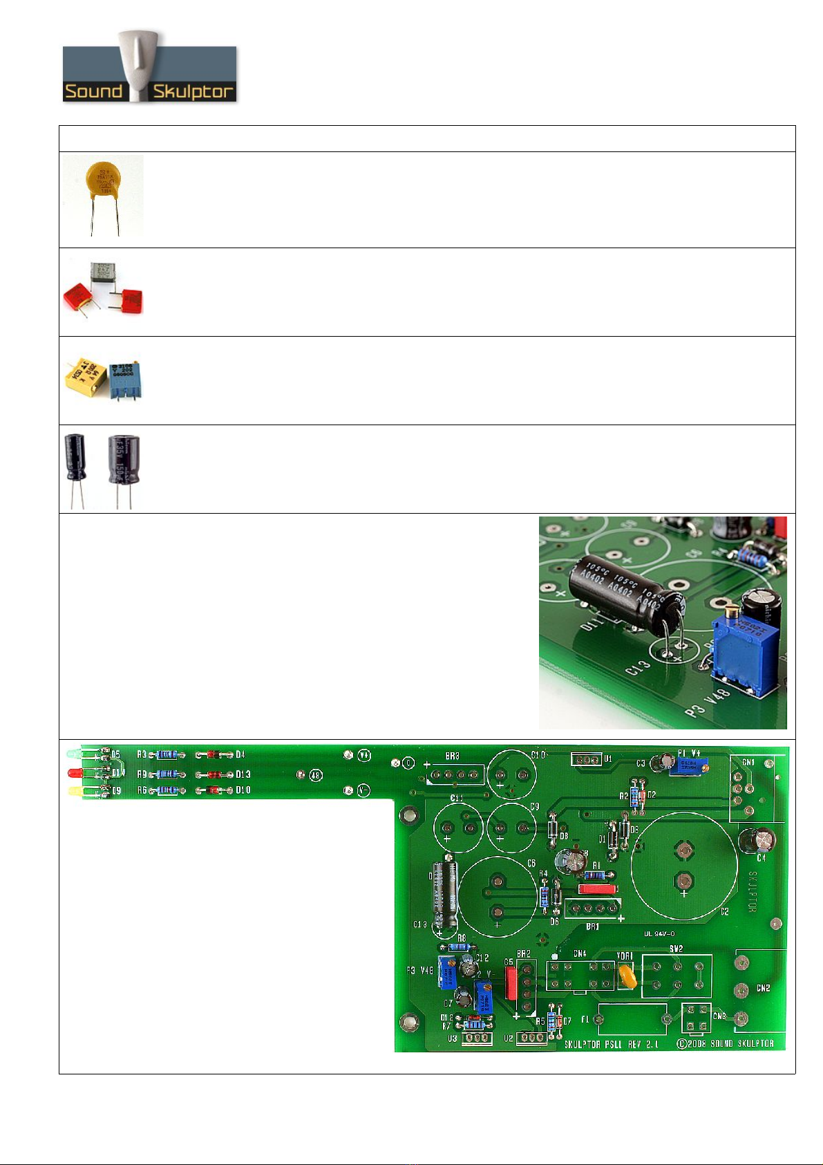
5. VDR1
Add the VDR1 varistor.
6. Film capacitors
Add C1 and C5.
7. Trimmer potentiometers
Add P1, P2, P3. older one pin, check verticality then solder the other pins.
8. mall electrolytic capacitors
Add C3, C4, C7, C8, C12.
older one lead first, adjust verticality then solder the second lead.
Warning : The +lead must go into the +hole. Do not reverse (they may explode !)
9. C13
Add C13 but lay it down horizontally on the board, as shown
on the photograph. This is because it is high and will be in the
way when we will be screwing the regulator heatsinks, later
on.
Copyright ©2008 ound kulptor
www.soundskulptor.com
Document revision 1.1 – Last modification : 21/04/08
P L1 Assembly guide
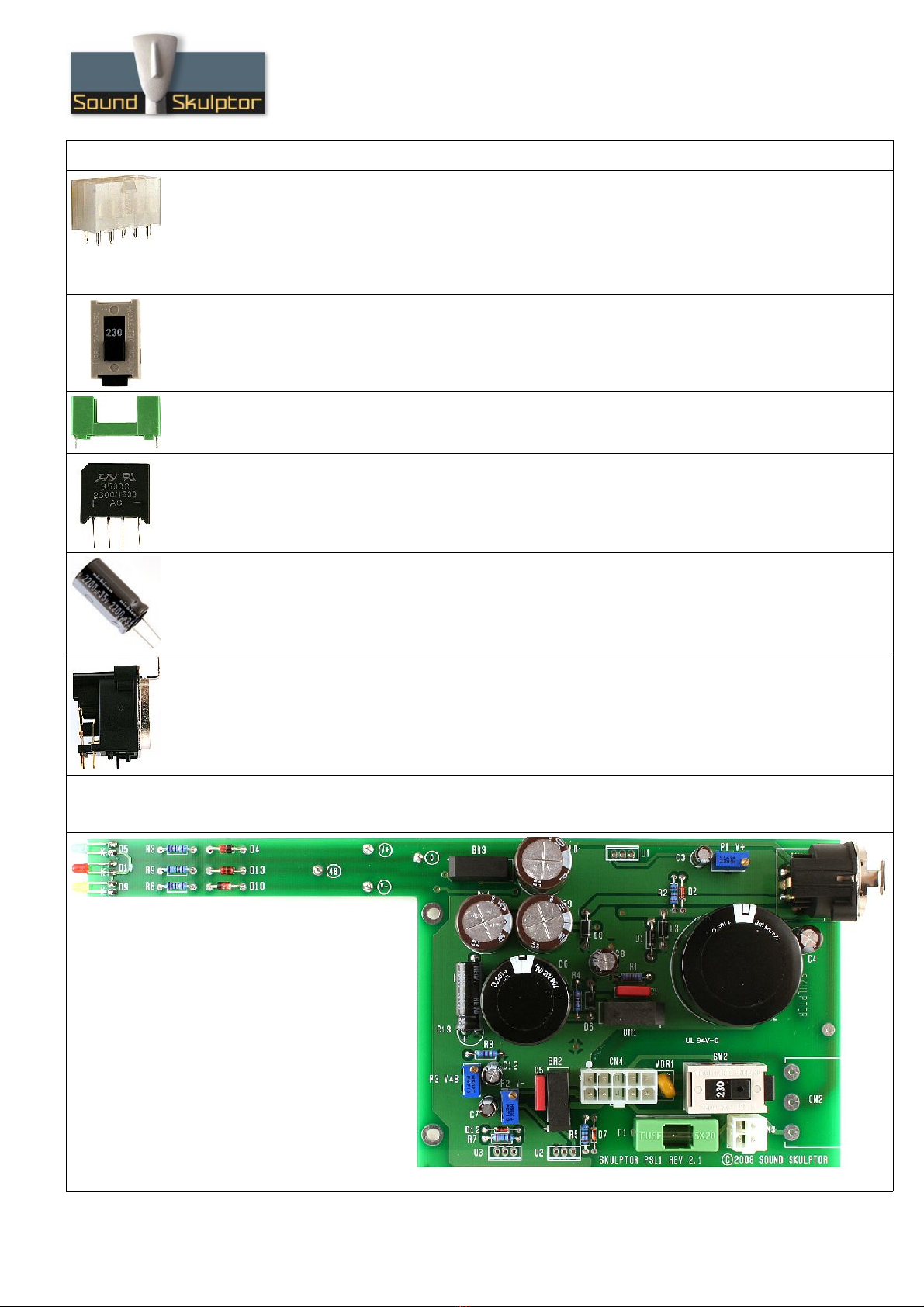
10. Connectors
Add CN3, CN4.
After soldering, cut the pins flush. The pins are not very long but they carry mains voltage and the
clearance distance between them and the case must be respected.
Warning : Make sure to position the connector in the right direction which is identified by the latching pin
on the PCB.
11. 115/230V elector switch
Add W2.
12. Fuse holder
Add the fuse holder.
13. Bridge rectifiers
Add BR1, BR2, BR3.
Warning : Make sure to respect the direction of the bridge rectifiers, It is marked by + and - signs.
14. Medium size electrolytics
Add C9, C10, C11.
15. XLR ocket
Add CN1. The position of the socket is critical for a good backplate matching. It must sit flat on the
PCB. Press firmly the socket on the PCB and solder one of the centre pins. Check position then solder
the other pins.
16. Large Electrolytics
Add C2, C6
Copyright ©2008 ound kulptor
www.soundskulptor.com
Document revision 1.1 – Last modification : 21/04/08
P L1 Assembly guide
17. Board inspection
Brush the solder side of the board with a hard tooth brush to remove any remaining solder bits.
Make a full visual check. Any missing component on the board ? Any remaining component in the box ?
When everything is correct move forward with the case assembly.
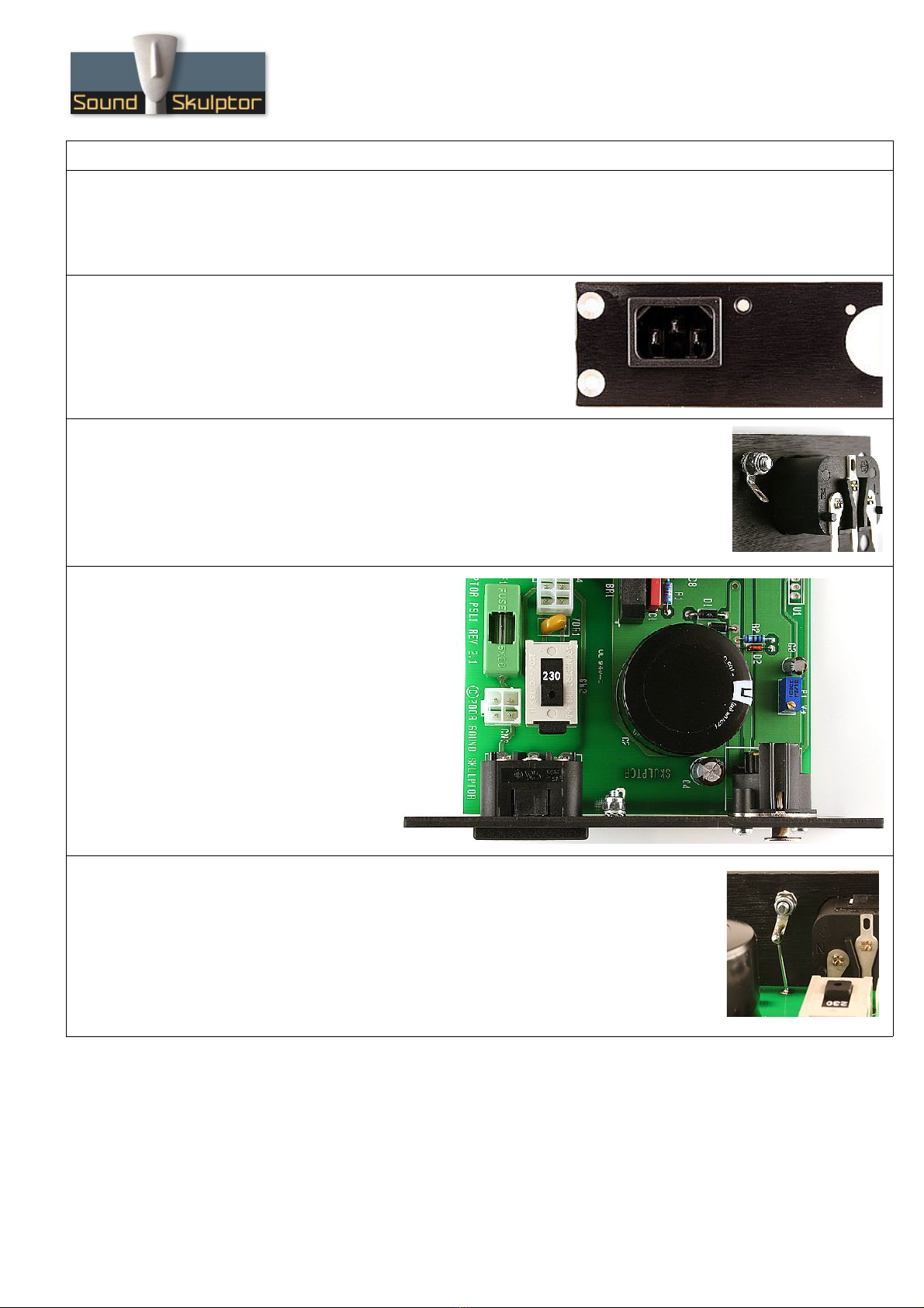
18. IEC connector assembly
nap the IEC connector into the back plate.
19. Case connection
Insert an M3x10 screw into the backplate. Add a shakeproof washer, a solder
tag and finally a self locking nut. Tighten together.
20. Backplate mounting
Put the backplate in place, by
inserting the IEC connector pins
into the PCB and by fitting the
XLR in the plate cutout. ecure
the XLR with two 2.9x9.5 self
taping screws.
older the IEC connector pins
after checking that the PCB if
perfectly parallel to the backplate
long side.
21. Earth connection
Use the 0,9mm tined wire to make the connection between the solder tag and
the PCB
Copyright ©2008 ound kulptor
www.soundskulptor.com
Document revision 1.1 – Last modification : 21/04/08
P L1 Assembly guide
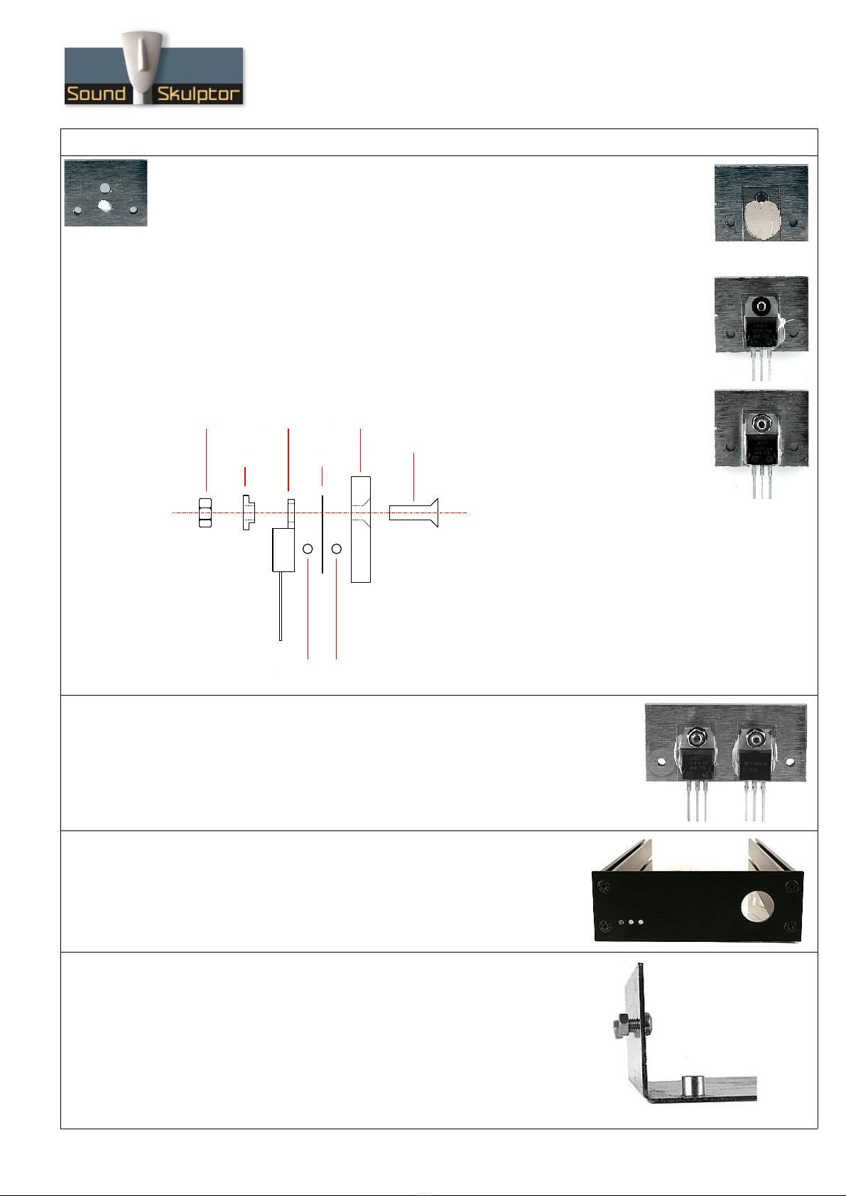
22. ingle heatsink assembly
Place a drop of thermal compound on the heatsink front face, the volume of a grain of
rice. The back face can be identified by the countersunk hole.
Next place the mica insulator.
Place a second drop of thermal compound on the mica insulator.
Insert the M3x10 countersunk screw from the back, the LM317 regulator and the
Insulating shoulder washer.
Place the M3 nut and tighten all together.
Use your digital multimeter in the Ohm position to check that there is no connection
between the heatsink and the center pin of the regulator.
23. Dual heatsink assembly
Repeat the same operations for the two regulators of the dual heatsink.
LM317 on the left,
TL783 on the right.
24. Case assembly
Assemble the front plate and the two sides of the case with four
black M4 countersunk srews.
The internal face of the sides is the one with a single groove.
25. Transformer plate assembly
Place two M3x6 pan head screws with two nuts on the transformer plate
and slide it into the right side of the case.
Copyright ©2008 ound kulptor
M3x10 screw
Heatsink
Thermal compound
Mica
insulator
Regulator
houlder
washer
Nut
www.soundskulptor.com
Document revision 1.1 – Last modification : 21/04/08
P L1 Assembly guide
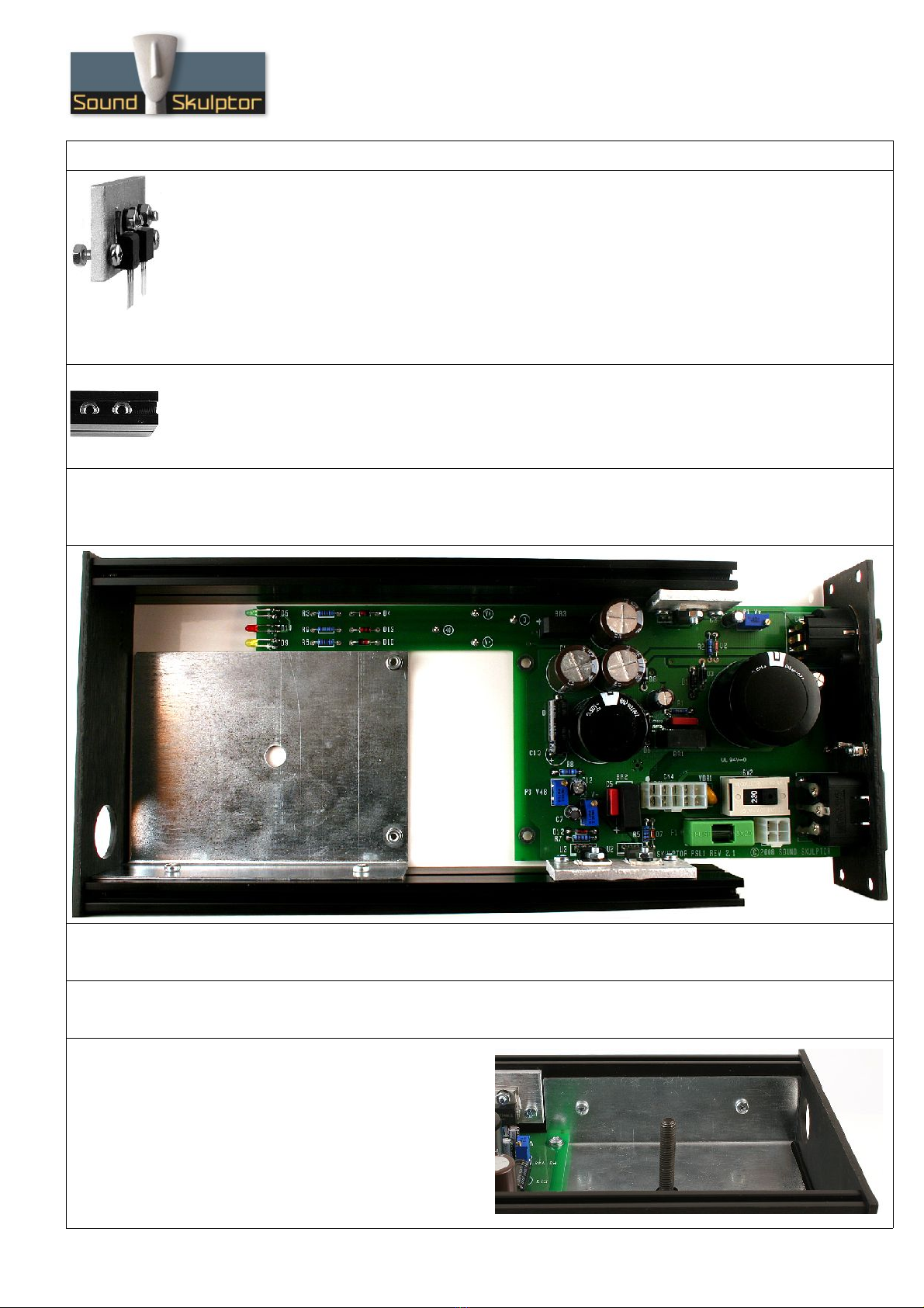
26. Regulator heatsinks assembly
Place two M3x10 pan head screws with two nuts on the regulator heatsinks. Insert the regulator pins
into the PCB. Do not solder yet.
27. Top and bottom cover fixing nuts
Add 2 nuts in the top and bottom grooves of both sides of the case (for a total of 8 nuts). They will be
used to attach top and bottom covers.
28. PCB insertion
Insert the PCB into position by sliding the heatsink screws into the case grooves. Make sure the LEDs fit
into the front plat holes.
29. Back plate assembly
Attach the back plate with four M4 countersunk srews.
30. PCB fixing
Attach the PCB to the transformer plate with 2 M3x6 pan head screws.
31. Transformer plate fixing
Tighten firmly the 2 transformer plate fixing
screws.
Copyright ©2008 ound kulptor

www.soundskulptor.com
Document revision 1.1 – Last modification : 21/04/08
P L1 Assembly guide
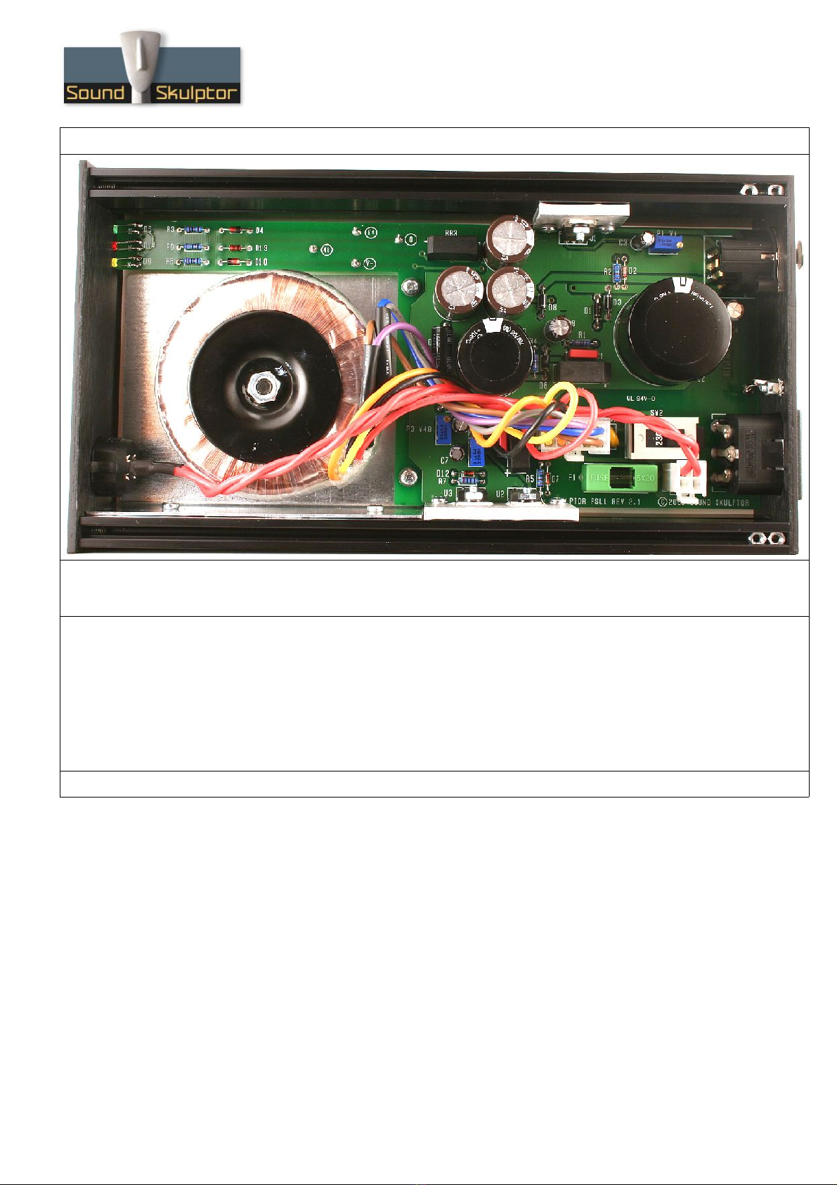
32. Heatsinks fixing
Tighten the 2 fixing screws of both heatsinks.
older the 3 regulators. Cut the pins flush.
33. witch wiring
The power switch must be soldered to the 2 wires of the pre-assembled connector CN3.
Insert two 15mm pieces of heatshrink tube on the wires. older the wires to the power
switch. hrink the tubes on the switch pins with a heat gun.
34. witch fixing
Insert the switch into the front plate and plug in the connector.
35. Transformer fixing
Attach the transformer. The nut should be
tightened to prevent any transformer movement
but without crushing the windings.
Plug in the transformer connector.
Copyright ©2008 ound kulptor
Transformer plate
oft washer
oft washer
Transformer
Mounting disc
Nut
www.soundskulptor.com
Document revision 1.1 – Last modification : 21/04/08
P L1 Assembly guide
36. etup
Follow the instructions of the P L1 etup Guide.
37. Closing the case
With the help of the bottom cover, position the fixing nuts in front of the holes.
Place the mylar insulating sheet on the bottom of the PCB.
Place the bottom cover and secure it with 4 black screws.
Place the top cover and secure it with 4 black screws.
tick the four self adhesive rubber feet on the bottom of the case.
38. Congratulations, you're done !
Copyright ©2008 ound kulptor
Table of contents


